EP0723064A2 - Profilé pour cadre de portes, fenêtres ou façades avec matière intumescent - Google Patents
Profilé pour cadre de portes, fenêtres ou façades avec matière intumescent Download PDFInfo
- Publication number
- EP0723064A2 EP0723064A2 EP96100055A EP96100055A EP0723064A2 EP 0723064 A2 EP0723064 A2 EP 0723064A2 EP 96100055 A EP96100055 A EP 96100055A EP 96100055 A EP96100055 A EP 96100055A EP 0723064 A2 EP0723064 A2 EP 0723064A2
- Authority
- EP
- European Patent Office
- Prior art keywords
- profile
- building material
- strip
- frame profile
- recess
- Prior art date
- Legal status (The legal status is an assumption and is not a legal conclusion. Google has not performed a legal analysis and makes no representation as to the accuracy of the status listed.)
- Granted
Links
Images

Classifications
-
- E—FIXED CONSTRUCTIONS
- E06—DOORS, WINDOWS, SHUTTERS, OR ROLLER BLINDS IN GENERAL; LADDERS
- E06B—FIXED OR MOVABLE CLOSURES FOR OPENINGS IN BUILDINGS, VEHICLES, FENCES OR LIKE ENCLOSURES IN GENERAL, e.g. DOORS, WINDOWS, BLINDS, GATES
- E06B3/00—Window sashes, door leaves, or like elements for closing wall or like openings; Layout of fixed or moving closures, e.g. windows in wall or like openings; Features of rigidly-mounted outer frames relating to the mounting of wing frames
- E06B3/04—Wing frames not characterised by the manner of movement
- E06B3/263—Frames with special provision for insulation
- E06B3/26301—Frames with special provision for insulation with prefabricated insulating strips between two metal section members
-
- E—FIXED CONSTRUCTIONS
- E06—DOORS, WINDOWS, SHUTTERS, OR ROLLER BLINDS IN GENERAL; LADDERS
- E06B—FIXED OR MOVABLE CLOSURES FOR OPENINGS IN BUILDINGS, VEHICLES, FENCES OR LIKE ENCLOSURES IN GENERAL, e.g. DOORS, WINDOWS, BLINDS, GATES
- E06B5/00—Doors, windows, or like closures for special purposes; Border constructions therefor
- E06B5/10—Doors, windows, or like closures for special purposes; Border constructions therefor for protection against air-raid or other war-like action; for other protective purposes
- E06B5/16—Fireproof doors or similar closures; Adaptations of fixed constructions therefor
- E06B5/162—Fireproof doors having windows or other openings, e.g. for permitting ventilation or escape
-
- E—FIXED CONSTRUCTIONS
- E06—DOORS, WINDOWS, SHUTTERS, OR ROLLER BLINDS IN GENERAL; LADDERS
- E06B—FIXED OR MOVABLE CLOSURES FOR OPENINGS IN BUILDINGS, VEHICLES, FENCES OR LIKE ENCLOSURES IN GENERAL, e.g. DOORS, WINDOWS, BLINDS, GATES
- E06B3/00—Window sashes, door leaves, or like elements for closing wall or like openings; Layout of fixed or moving closures, e.g. windows in wall or like openings; Features of rigidly-mounted outer frames relating to the mounting of wing frames
- E06B3/04—Wing frames not characterised by the manner of movement
- E06B3/263—Frames with special provision for insulation
- E06B2003/26394—Strengthening arrangements in case of fire
-
- E—FIXED CONSTRUCTIONS
- E06—DOORS, WINDOWS, SHUTTERS, OR ROLLER BLINDS IN GENERAL; LADDERS
- E06B—FIXED OR MOVABLE CLOSURES FOR OPENINGS IN BUILDINGS, VEHICLES, FENCES OR LIKE ENCLOSURES IN GENERAL, e.g. DOORS, WINDOWS, BLINDS, GATES
- E06B3/00—Window sashes, door leaves, or like elements for closing wall or like openings; Layout of fixed or moving closures, e.g. windows in wall or like openings; Features of rigidly-mounted outer frames relating to the mounting of wing frames
- E06B3/04—Wing frames not characterised by the manner of movement
- E06B3/263—Frames with special provision for insulation
- E06B2003/26396—Frames with special provision for insulation specially adapted for sheet metal frames
Definitions
- the invention relates to a frame profile for windows, doors or facades, with an interior and an exterior, each closed in cross section metal hollow profile, which have at least one fire-resistant connector between them and are firmly connected.
- a frame profile with the aforementioned features is known from DE-U-91 08 751. It meets standardized requirements for fire protection components. It is a composite profile, a further metal hollow profile is arranged between the metal hollow profiles and these connected fire-resistant connectors. This frame profile is inserted between two insulating glass panes arranged in the same plane and has no free end face, so it does not adjoin a rebate space.
- a fire protection door with a surrounding frame is known, in the front side of which is assigned to the rebate space an open groove is incorporated.
- the groove is profiled in a dovetail shape and is fitted with an insertable strip which clasps around the front edges of the groove and is provided with a hollow chamber.
- the frame is made of specially shaped profiles, which must be dovetailed in a complex manner on the rebate side.
- special door panels are required, which also cover the known frame on the rebate side. The forehead or rabbet side view of the known fire door is consequently and because of the provided bar inconsistent.
- the invention has for its object to improve a frame profile with the features mentioned so that a handsome appearance of the rebate side surface of the frame profile is achieved and at the same time a permanent fire protection function of the frame profile is ensured.
- the connector for forming a recess running longitudinally in the profile of at least one of the rebate space or end wall surfaces of the hollow metal profiles protrudes that one of the rebate space or. is arranged end face wall surfaces and the recess covering bar that foaming building material is housed in the recess in the event of fire, and that the bar melts in the event of fire before reaching the foaming temperature of the building material and thereby allows heat to enter the building material.
- the frame profile is specially adapted to fire protection tasks. It is comparatively insensitive to fire, because the metal hollow profiles have a very good heat stability and the fire-resistant connector ensures that the dimensional stability of the entire frame profile is guaranteed even with high fire safety requirements. It is only necessary to keep the fire-resistant connector slightly shorter in the connecting plane of the two hollow metal profiles vertically to the rebate space than this itself in order to create the recess for accommodating the foaming building material.
- the bar protects the building material inserted in this recess and ensures the visually appealing appearance of the frame profile from the rebate side. An optical treatment of the surface of the fire-resistant connector that is optically visible in the absence of a strip is not necessary.
- the strip covering the building material covers the frame profile on the rebate side, at least in the area of this building material.
- all requirements for the visual appearance of the frame profile can be met, namely geometric and colored designs of the strip, such as also any surface structures.
- the bar ensures protection of the foaming building material. Accidental or simply malicious access to the foaming building material is not possible.
- the melting of the strip leads to the foaming building material being subjected to the heat or energy required for the foaming, so that the fire protection function is guaranteed.
- skirting board is directly adjacent to the building material, this ensures that heat is transferred to the foaming building material without delay. There is no undue delay in foaming and therefore no unintentional hindrance to the fire protection effect.
- the frame profile can be advantageously designed in that the bar and the building material are assembled into a handling unit. As a result, it is possible to assemble the molding and the building material at the factory in order to achieve a functional unit. On the one hand it is ensured that the foaming building material and the strip always have the structurally predetermined relative position to each other and on the other hand it is achieved that both are assembled together with the frame profile, so that the installation or attachment of the foaming building material is not carried out incorrectly can. In this context, it is particularly important to check that the strip is properly seated on the frame profile, which not only ensures that the frame profile looks good, but also that the fire protection function is guaranteed by the foaming building material.
- the frame profile in such a way that the strip has two surrounding strips projecting at right angles on the profile side, the space between which is filled with the building material.
- the two surrounding ledges projecting on the profile side form a defined installation space for the foaming building material and thus also a protective space for this. This is necessary for room assembly operation on the frame profile, if this is for assembly with others Frame profiles is assembled or if it is assembled with further frame profiles, provided that the foaming building material is already attached. Its mechanically sensitive structure could otherwise lead to it being damaged.
- the perpendicularity of the projecting surrounding strips allows the strip to be inserted into a conventional recess with a rectangular or square cross section.
- the two surrounding strips hold a cover cladding the building material on the profile side.
- This cover cladding the building material not only protects it from the outside, but can also hold it in its installed position, for example by pinching it. In this way it is easily possible, for example, to hold slightly pre-compressed, foaming building material.
- the frame profile with its surrounding strips can be designed in such a way that the two surrounding strips are integrally connected to one another to form a rectangular cross-section by a cover wall surrounding the building material.
- the one-piece construction of the cover wall with the other parts of the strip leads to a substantial stabilization of the component.
- the foaming building material is completely enclosed and protected accordingly.
- the rectangular cross-section of the area defined by the two surrounding strips and the one-piece cover wall corresponds to a conventional, rectangular, cross-section-shaped recess and thus an optimal use of the existing construction volume.
- the recess is completely filled and the strip lies flat against the rebate-side wall of the frame profile or can be arranged flush with the rebate-side profile surfaces if it does not cover the rebate-side profile surfaces .
- the result is an optimal use of space and an appealing exterior.
- a frame profile can be designed in such a way that the bar has a retaining bar projecting at right angles on the profile side, on each side of which foaming building material is arranged. This simplifies the structure of the bar. It is particularly independent of the dimensioning of the width of the continuous recess and can be used more universally.
- a simple attachment of the bar to the frame profile can be achieved in that the holding bar arranged in the center of the recess is pressed through the recess into a holding groove of the frame profile.
- a frame profile can be developed in that the bar and the building material fill the recess.
- the available cross-section is optimally used. Since the bar with the foaming building material fills the recess formed by the recess of the connector between the hollow metal profiles, on the one hand the connection strength of the two hollow metal profiles is only slightly impaired, but on the other hand a structurally simple adjustment of the cross section of the frame profile is achieved.
- the bar In order to improve the visual impression of the frame profile from the rebate side, it is advantageous if the bar covers all profile wall surfaces on the rebate side.
- the strip then also simultaneously provides mechanical protection for the surfaces of the hollow metal profiles on the rebate side.
- the strip has a flat, first angled leg, which covers all of the rebate-side profile wall surfaces, and a second angled leg, which is perpendicular to it, and which covers a fold-over surface of a hollow metal profile facing the rebate area.
- first angled leg which covers all of the rebate-side profile wall surfaces
- second angled leg which is perpendicular to it, and which covers a fold-over surface of a hollow metal profile facing the rebate area.
- the frame profile To adapt the frame profile to conventional frame environments, it is designed so that the outer profile of the hollow metal profile is provided with a cladding on the outside of the room in a flush fold-side connection to the strip covering the foaming building material.
- the bar covering the foaming material is thus included in a cladding of the outer metal hollow profile, so that a complete adaptation to conventional outside areas can be achieved. It is not recognizable from the outside that the frame profile is a special fire protection profile. Since the hollow metal profiles also have considerable stability, the frame profile is correspondingly burglar-resistant.
- the frame profile can be designed in such a way that the hollow metal profile inside the profile has at least one recess on the inside of the room, in which building material which is foaming in the event of a fire is arranged. Improved fire protection is achieved.
- the additional building material provided for this purpose is preferably arranged on the rebate side, where it is covered by another frame component, namely by a rollover of a wing, so that the building material which foams up in the event of a fire seals the gap between the wing rollover and the frame profile parallel to the frame plane.
- the frame profile can furthermore be designed such that the building material arranged in the recess of the hollow metal profile inside the profile is covered with a strip leg of the strip on the rebate area side that is flush with this profile and / or that the strip has predetermined melting points.
- the covering of the building material provides a corresponding mechanical protection during normal handling of the window and ensures a handsome appearance due to the strip leg lying flush with the profile.
- the cost of covering is kept small, since no separate strip part has to be used, but the covering strip which is required anyway only needs to have an additional covering leg.
- the building material that foams up in the event of a fire is able to break the strip at a time when the strip may only be in places has melted. As a result of this breaking open, faster sealing is achieved.
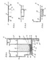
- the frame profile 10 shown in FIG. 1 consists of two hollow metal profiles 19, 20 which are arranged at a distance from one another and are held firmly together by a connector 21. The three aforementioned parts are glued together, for example.
- Each of the metal hollow profiles 19, 20 has a wall surface 22, 23 facing the rebate space 11.
- the hollow metal profile 20 also has a rollover 28 with a rollover surface 25 facing the rebate area 11.
- All the wall surfaces 22, 23, 25 facing the rebate space 11 are covered by a strip 15 which has a flat angled leg 24 which is smooth towards the rebate space 11 and a right-angled leg 26 which is also arranged at right angles to the rebate space 11.
- the two angle legs 24, 26 are comparatively close to the profile wall surfaces 22, 23, 25, so that they are not very bulky. They completely clad the metal hollow profiles 19, 20 on the rebate side.
- the frame profile 10 is a frame spar of a frame. Its metal hollow profile 20 on the outside of the frame is provided on the outside of the frame with a cladding 27 which, for example, consists of plastic and is fastened in the usual way.
- the cladding 27 encompasses the rollover 28 from the outside up to the rollover surface 25, so that it is flush with the angle leg 26 of the bar 15 lies. This results in a complete cladding of the entire frame profile on the outside of the frame and on the rebate side.
- the strip 15 has, from its angle leg 24, profile strips 16 projecting at right angles on the profile side. These cover strips 16 stabilize the strip 15 and engage in a recess 13 in the frame profile 10, which is produced in that the connector 21 is kept shorter in the plane of representation perpendicular to the rebate space 11 when the metal hollow profiles 19.20. Their rebate-side wall surfaces 22, 23 thus project over the rebate-side wall surface 21 of the connector 21.
- the strip 15 can be fixed on the frame profile 10, for example by clamping or gluing. Screwing through the angle leg 24 into the connector 21 is also possible, e.g. at the screw point marked by 29.
- the space between the surrounding strips 16 is essentially filled by building material 14 which foams in the event of a fire.
- building material 14 is temperature-sensitive and experiences a considerable increase in volume if its temperature or its ambient temperature increases to a value that experience has shown to occur in the event of a fire.
- the building material contains a temperature-sensitive substance which gasifies at a predetermined temperature and thereby increases the volume of the building material many times over.
- Such a building material is usually somewhat pre-compressed in order to keep its installation volume small.
- a cover 18 is provided between the surrounding strips 16, which engages in a form-fitting manner in grooves which are provided on the surrounding strips 16 on the construction material side.
- the installation of the building material 14 is overall such that it bears directly on the profile-side inner wall of the angle leg 24. An intermediate volume that transmits poor energy is thereby avoided.
- the cover strip 15 must be such that it does not hinder the foaming. It is therefore made of a plastic whose melting temperature is lower than the temperature from which the building material foams. When the plastic of the strip 15 is melted, heat access to the building material 14 is made possible, so that it can expand through those areas of the strip 15 from which the plastic has melted away. The foaming of the building material can help push the melted plastic away.
- FIG. 2 shows a cross-sectional configuration of the strip 15 with two right-angled projecting surrounding strips 16, which in turn are integrally connected to one another by a cover wall 18 '.
- the result is an overall rectangular cross section, which is adapted to the cross section of the recess 13, so that the recess 13 is completely filled.
- the covering wall 18 ', together with the surrounding strips 16, stabilizes the strip 15 and encloses the building material 14 securely, so that it can be introduced with high pre-compression, which, in the event of a melting of the angled leg 24 in the event of a fire, contributes to the foaming building material 14 quickly entering can penetrate the rebate 16.
- FIG. 3 shows a configuration of a cross section of a strip 15 corresponding to the configuration according to FIG. 2, but only a single smooth strip leg 30 is provided to cover the two profile wall surfaces 22, 23 on the rebate space side.
- the building material that foams up in the event of a fire is not shown, but is present.
- the cover strip 15 consists of a cover leg 31, on the outer edges 31 'of which surround strips 16 are fastened, each of which has a fastening leg 32 which is parallel to the cover leg 31.
- These Design is production-related, but also permits the arrangement of building material 14 which foams up in the event of a fire in the intermediate space 17 between the surrounding strips 16.
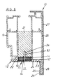
- FIG. 5 shows a cross section through a frame profile 10, for the details of which reference is made to FIG. 1 insofar as the same reference numerals are entered in FIG.
- the strip 15 assembled with this frame profile 10 has a retaining strip 16 'projecting at right angles on the profile side with a free ribbed end 33 which is pressed into a retaining groove 34 of the connector.
- the angle leg 24 lies tightly against the profile wall surfaces 22, 23.
- the holding strip 16 'foaming building material 14 is arranged on both sides. This is preferably designed to be dimensionally stable. Since only a single retaining strip 16 'has to be accommodated in the region of the recess 13, the remaining space of the recess 13 is available for the arrangement of foaming building material 14 or the recess 13 is reduced.
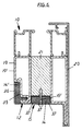
- the frame profile 10 shown in cross section in FIG. 6 corresponds to the profile shown in FIG. 5 with regard to the profiling of the metal hollow profiles 19, 20 and the connector 21 located between them.
- the building material 14 which foams up in the event of a fire and the formation of the strip 15 on the rebate side side with the retaining strip 16 'projecting on the connector side is also unchanged.
- the hollow metal profile 19 inside the profile is provided in the vicinity of the rebate space with a recess 35, which has also already been shown, for example, in FIG. 5, but which is filled in FIG. 6 with building material 14 'which foams in the event of a fire.
- building material 14 ' which foams in the event of a fire.
- this area there is usually a flap overlap inside the room.
- the frame-parallel gap between this sash overlap and the adjacent area of the frame profile 10 can be sealed by the building material 14 'foaming.
- the building material 14 'can also partially fill up the rebate area. So this partly also help to fill the rebate area.
- the strip 15 was provided with a strip leg 36 which is flush with the inner surface 19' of the frame.
- This strip leg 36 is at right angles and in one piece with the strip 15, which completely covers the frame profile 10 towards the rebate space, that is to say covers the side wall 12 of the frame profile 10 on the rebate space side.
- the strip 15 is provided with predetermined melting points 37.
- Two predetermined melting points 37 are located immediately adjacent to the centrally arranged holding strip 16 ', and a further predetermined melting point is located in the vicinity of the hollow metal profiles 19, 20.
- the strip 15 melts, preferably at the predetermined melting points 37. This makes it easier for the foaming building material 14 to push away the strip areas located between predetermined breaking points 37 and accordingly contributes to the faster filling of the rebate space.
Landscapes
- Engineering & Computer Science (AREA)
- Civil Engineering (AREA)
- Structural Engineering (AREA)
- Special Wing (AREA)
- Securing Of Glass Panes Or The Like (AREA)
- Wing Frames And Configurations (AREA)
- Paper (AREA)
- Glass Compositions (AREA)
Applications Claiming Priority (2)
| Application Number | Priority Date | Filing Date | Title |
|---|---|---|---|
| DE29500148U | 1995-01-05 | ||
| DE29500148U DE29500148U1 (de) | 1995-01-05 | 1995-01-05 | Rahmenprofil für Fenster oder Türen |
Publications (3)
| Publication Number | Publication Date |
|---|---|
| EP0723064A2 true EP0723064A2 (fr) | 1996-07-24 |
| EP0723064A3 EP0723064A3 (fr) | 1997-11-19 |
| EP0723064B1 EP0723064B1 (fr) | 1998-10-14 |
Family
ID=8002217
Family Applications (1)
| Application Number | Title | Priority Date | Filing Date |
|---|---|---|---|
| EP96100055A Expired - Lifetime EP0723064B1 (fr) | 1995-01-05 | 1996-01-04 | Profilé pour cadre de portes, fenêtres ou façades avec matière intumescente |
Country Status (3)
| Country | Link |
|---|---|
| EP (1) | EP0723064B1 (fr) |
| AT (1) | ATE172273T1 (fr) |
| DE (2) | DE29500148U1 (fr) |
Cited By (7)
| Publication number | Priority date | Publication date | Assignee | Title |
|---|---|---|---|---|
| GB2309728A (en) * | 1996-02-01 | 1997-08-06 | Lorient Polyprod Ltd | Fire resistant frame member made from a heat meltable plastic having internal cavities selectively filled with an intumescent material. |
| EP1681430A3 (fr) * | 2005-01-18 | 2009-05-06 | Forster Rohr- & Profiltechnik AG | Profilé composite pour cadres d'éléments de paroi, portes et fenêtres |
| CN110714691A (zh) * | 2019-10-22 | 2020-01-21 | 英普瑞科技(嘉兴)有限公司 | 三腔隔热钢型材门窗结构 |
| US11486150B2 (en) | 2016-12-20 | 2022-11-01 | Clarkwestern Dietrich Building Systems Llc | Finishing accessory with backing strip |
| US11885138B2 (en) | 2020-11-12 | 2024-01-30 | Clarkwestern Dietrich Building Systems Llc | Control joint |
| USD1026252S1 (en) | 2020-11-12 | 2024-05-07 | Clarkwestern Dietrich Building Systems Llc | Control joint |
| US12618242B2 (en) | 2023-12-18 | 2026-05-05 | Clarkwestern Dietrich Building Systems Llc | Control joint |
Families Citing this family (3)
| Publication number | Priority date | Publication date | Assignee | Title |
|---|---|---|---|---|
| DE19809691A1 (de) * | 1998-03-06 | 1999-09-09 | Niemann | Falzabdeckleiste eines Tür- oder Fensterrahmens |
| DE20002142U1 (de) * | 2000-02-08 | 2001-06-07 | Montanstahl Sa, Stabio | Fenster-/Türsystem |
| IT1398494B1 (it) * | 2010-03-11 | 2013-03-01 | Benussi | Profilo per serramenti in particolare del tipo tagliafuoco o similari nonche' serramento che include tale profilo |
Family Cites Families (10)
| Publication number | Priority date | Publication date | Assignee | Title |
|---|---|---|---|---|
| GB1529733A (en) * | 1975-11-27 | 1978-10-25 | Dixon Int Ltd | Fire resistant seals |
| US4424653A (en) * | 1980-10-10 | 1984-01-10 | Heinen Hans Dieter | Fire-proof window |
| DE3423550C1 (de) * | 1984-06-26 | 1985-04-18 | Hörmann KG Freisen, 6699 Freisen | Feuerschutztür |
| DE8717453U1 (de) * | 1987-06-11 | 1988-11-10 | Zapp, Wolfgang D., Creutzwald | Fenster- oder Türblatt aus zwei Rahmen |
| GB2212539B (en) * | 1987-11-13 | 1991-06-26 | Briggs Amasco Ltd | Fire-resistant seal |
| DE3939149C1 (fr) * | 1989-11-27 | 1991-01-03 | Schott Glaswerke, 6500 Mainz, De | |
| DE9108751U1 (de) * | 1991-07-16 | 1991-10-10 | Hermann Forster Ag, Arbon | Verbundprofil für Rahmen von Wandelementen, Türen und Fenstern |
| DE4219838A1 (de) * | 1992-06-17 | 1993-12-23 | Schott Glaswerke | Brandschutzverglasung |
| DE4303573C2 (de) * | 1993-02-08 | 2002-12-12 | Treco Gmbh | Rahmen mit einem Dichtungssystem mit Brandschutzwirkung |
| NL9401613A (nl) * | 1994-09-30 | 1996-05-01 | Reynolds Aluminium Bv | Brandwerend, aluminium kozijn. |
-
1995
- 1995-01-05 DE DE29500148U patent/DE29500148U1/de not_active Expired - Lifetime
-
1996
- 1996-01-04 DE DE59600652T patent/DE59600652D1/de not_active Expired - Fee Related
- 1996-01-04 EP EP96100055A patent/EP0723064B1/fr not_active Expired - Lifetime
- 1996-01-04 AT AT96100055T patent/ATE172273T1/de not_active IP Right Cessation
Cited By (11)
| Publication number | Priority date | Publication date | Assignee | Title |
|---|---|---|---|---|
| GB2309728A (en) * | 1996-02-01 | 1997-08-06 | Lorient Polyprod Ltd | Fire resistant frame member made from a heat meltable plastic having internal cavities selectively filled with an intumescent material. |
| GB2309728B (en) * | 1996-02-01 | 1999-09-08 | Lorient Polyprod Ltd | Structural frame member |
| EP1681430A3 (fr) * | 2005-01-18 | 2009-05-06 | Forster Rohr- & Profiltechnik AG | Profilé composite pour cadres d'éléments de paroi, portes et fenêtres |
| US11486150B2 (en) | 2016-12-20 | 2022-11-01 | Clarkwestern Dietrich Building Systems Llc | Finishing accessory with backing strip |
| US11725401B2 (en) | 2016-12-20 | 2023-08-15 | Clarkwestern Dietrich Building Systems Llc | Finishing accessory with backing strip |
| US12018496B2 (en) | 2016-12-20 | 2024-06-25 | Clarkwestern Dietrich Building Systems Llc | Finishing accessory with backing strip |
| US12486676B2 (en) | 2016-12-20 | 2025-12-02 | Clarkwestern Dietrich Building Systems Llc | Finishing accessory with backing strip |
| CN110714691A (zh) * | 2019-10-22 | 2020-01-21 | 英普瑞科技(嘉兴)有限公司 | 三腔隔热钢型材门窗结构 |
| US11885138B2 (en) | 2020-11-12 | 2024-01-30 | Clarkwestern Dietrich Building Systems Llc | Control joint |
| USD1026252S1 (en) | 2020-11-12 | 2024-05-07 | Clarkwestern Dietrich Building Systems Llc | Control joint |
| US12618242B2 (en) | 2023-12-18 | 2026-05-05 | Clarkwestern Dietrich Building Systems Llc | Control joint |
Also Published As
| Publication number | Publication date |
|---|---|
| DE29500148U1 (de) | 1996-05-09 |
| ATE172273T1 (de) | 1998-10-15 |
| EP0723064A3 (fr) | 1997-11-19 |
| EP0723064B1 (fr) | 1998-10-14 |
| DE59600652D1 (de) | 1998-11-19 |
Similar Documents
| Publication | Publication Date | Title |
|---|---|---|
| WO2001007744A1 (fr) | Porte ou fenetre coupe-feu | |
| EP1943406A2 (fr) | Element constitutif | |
| EP0723064B1 (fr) | Profilé pour cadre de portes, fenêtres ou façades avec matière intumescente | |
| DE3739020C2 (de) | Verglaste und/oder mit Füllung versehene Brandschutztüre | |
| EP0298354B1 (fr) | Châssis en matière plastique pour fenêtres, portes ou des choses pareilles | |
| EP0505934B1 (fr) | Porte coupe-feu vitrée | |
| DE29620153U1 (de) | Verbindung für winklig aneinanderstoßende Hohlprofilstäbe | |
| EP0063623A1 (fr) | Ensemble constructif de plusieurs profilés assortis, extrudés en matière plastique, pour la fabrication de fenêtres, portes et analogues | |
| EP0725203B1 (fr) | Armature pour portes, fenêtres ou façades | |
| AT518200B1 (de) | Kombi-Glashalter und damit ausgerüstetes Holz-Alu-Verbundfenster | |
| DE19533273A1 (de) | Halterung für eine Scheibe in einem Profilrahmen | |
| AT392997B (de) | Fenster | |
| DE60130085T2 (de) | Kunststoffflügel, sowie sein Herstellungsverfahren und zweiflügelige Öffnung, z.B. für ein Fenster | |
| DE19531040A1 (de) | Schutzvorrichtung für Bauelemente wie Fenster, Türen oder dergleichen | |
| DE29704349U1 (de) | Hohlprofil, insbesondere aus Kunststoff, zur Bildung eines Abdeckrahmens zur Verkleidung von Holzrahmen | |
| DE20100617U1 (de) | Rahmenprofilanordnung | |
| DE9308300U1 (de) | Eckzarge für Türen o.dgl. | |
| EP0997601A2 (fr) | Eléments d'habillage | |
| EP1728934A2 (fr) | Profilé pour cadres de fenêtres, cloisons ou portes | |
| DE102018126659B4 (de) | Blendrahmenprofil für Türen und Fenster mit Zusatzkomponenten | |
| DE102016107949A1 (de) | Profilrahmen für eine Tür, ein Fenster oder dgl. sowie ein Verfahren zur Herstellung eines derartigen Profilrahmens | |
| EP0730079A1 (fr) | Elément de façade, notamment porte ou fenêtre | |
| DE202005021295U1 (de) | Pfosten-Riegelkonstruktion | |
| DE3444702C2 (de) | Fensterwand mit Sprossen aus Stahlbetonfertigteilen und einem Gewände zur Aufnahme einer Brandschutztür | |
| DE3518824C1 (de) | Einrichtung zur Bildung einer gegenüber Feuer und Wärme dichten Verbindung zwischen den stumpf aneinanderstoßenden Schmalseiten von feuerhemmenden Bauteilen |
Legal Events
| Date | Code | Title | Description |
|---|---|---|---|
| PUAI | Public reference made under article 153(3) epc to a published international application that has entered the european phase |
Free format text: ORIGINAL CODE: 0009012 |
|
| AK | Designated contracting states |
Kind code of ref document: A2 Designated state(s): AT BE CH DE DK FR GB IT LI NL SE |
|
| PUAL | Search report despatched |
Free format text: ORIGINAL CODE: 0009013 |
|
| AK | Designated contracting states |
Kind code of ref document: A3 Designated state(s): AT BE CH DE DK FR GB IT LI NL SE |
|
| 17P | Request for examination filed |
Effective date: 19971121 |
|
| GRAG | Despatch of communication of intention to grant |
Free format text: ORIGINAL CODE: EPIDOS AGRA |
|
| GRAG | Despatch of communication of intention to grant |
Free format text: ORIGINAL CODE: EPIDOS AGRA |
|
| GRAH | Despatch of communication of intention to grant a patent |
Free format text: ORIGINAL CODE: EPIDOS IGRA |
|
| 17Q | First examination report despatched |
Effective date: 19980226 |
|
| GRAH | Despatch of communication of intention to grant a patent |
Free format text: ORIGINAL CODE: EPIDOS IGRA |
|
| GRAA | (expected) grant |
Free format text: ORIGINAL CODE: 0009210 |
|
| AK | Designated contracting states |
Kind code of ref document: B1 Designated state(s): AT BE CH DE DK FR GB IT LI NL SE |
|
| PG25 | Lapsed in a contracting state [announced via postgrant information from national office to epo] |
Ref country code: NL Free format text: LAPSE BECAUSE OF FAILURE TO SUBMIT A TRANSLATION OF THE DESCRIPTION OR TO PAY THE FEE WITHIN THE PRESCRIBED TIME-LIMIT Effective date: 19981014 Ref country code: IT Free format text: LAPSE BECAUSE OF FAILURE TO SUBMIT A TRANSLATION OF THE DESCRIPTION OR TO PAY THE FEE WITHIN THE PRE;WARNING: LAPSES OF ITALIAN PATENTS WITH EFFECTIVE DATE BEFORE 2007 MAY HAVE OCCURRED AT ANY TIME BEFORE 2007. THE CORRECT EFFECTIVE DATE MAY BE DIFFERENT FROM THE ONE RECORDED.SCRIBED TIME-LIMIT Effective date: 19981014 Ref country code: GB Free format text: LAPSE BECAUSE OF FAILURE TO SUBMIT A TRANSLATION OF THE DESCRIPTION OR TO PAY THE FEE WITHIN THE PRESCRIBED TIME-LIMIT Effective date: 19981014 Ref country code: FR Free format text: LAPSE BECAUSE OF FAILURE TO SUBMIT A TRANSLATION OF THE DESCRIPTION OR TO PAY THE FEE WITHIN THE PRESCRIBED TIME-LIMIT Effective date: 19981014 |
|
| REF | Corresponds to: |
Ref document number: 172273 Country of ref document: AT Date of ref document: 19981015 Kind code of ref document: T |
|
| REG | Reference to a national code |
Ref country code: CH Ref legal event code: EP |
|
| REF | Corresponds to: |
Ref document number: 59600652 Country of ref document: DE Date of ref document: 19981119 |
|
| PGFP | Annual fee paid to national office [announced via postgrant information from national office to epo] |
Ref country code: DE Payment date: 19981217 Year of fee payment: 4 |
|
| PGFP | Annual fee paid to national office [announced via postgrant information from national office to epo] |
Ref country code: AT Payment date: 19981228 Year of fee payment: 4 |
|
| PG25 | Lapsed in a contracting state [announced via postgrant information from national office to epo] |
Ref country code: SE Free format text: LAPSE BECAUSE OF FAILURE TO SUBMIT A TRANSLATION OF THE DESCRIPTION OR TO PAY THE FEE WITHIN THE PRESCRIBED TIME-LIMIT Effective date: 19990114 Ref country code: DK Free format text: LAPSE BECAUSE OF FAILURE TO SUBMIT A TRANSLATION OF THE DESCRIPTION OR TO PAY THE FEE WITHIN THE PRESCRIBED TIME-LIMIT Effective date: 19990114 |
|
| PG25 | Lapsed in a contracting state [announced via postgrant information from national office to epo] |
Ref country code: BE Free format text: LAPSE BECAUSE OF NON-PAYMENT OF DUE FEES Effective date: 19990131 |
|
| NLV1 | Nl: lapsed or annulled due to failure to fulfill the requirements of art. 29p and 29m of the patents act | ||
| EN | Fr: translation not filed | ||
| GBV | Gb: ep patent (uk) treated as always having been void in accordance with gb section 77(7)/1977 [no translation filed] |
Effective date: 19981014 |
|
| REG | Reference to a national code |
Ref country code: CH Ref legal event code: NV Representative=s name: E. BLUM & CO. PATENTANWAELTE |
|
| BERE | Be: lapsed |
Owner name: NIEMANN HANS-DIETER Effective date: 19990131 |
|
| PLBE | No opposition filed within time limit |
Free format text: ORIGINAL CODE: 0009261 |
|
| STAA | Information on the status of an ep patent application or granted ep patent |
Free format text: STATUS: NO OPPOSITION FILED WITHIN TIME LIMIT |
|
| 26N | No opposition filed | ||
| PG25 | Lapsed in a contracting state [announced via postgrant information from national office to epo] |
Ref country code: AT Free format text: LAPSE BECAUSE OF NON-PAYMENT OF DUE FEES Effective date: 20000104 |
|
| PG25 | Lapsed in a contracting state [announced via postgrant information from national office to epo] |
Ref country code: LI Free format text: LAPSE BECAUSE OF NON-PAYMENT OF DUE FEES Effective date: 20000131 Ref country code: CH Free format text: LAPSE BECAUSE OF NON-PAYMENT OF DUE FEES Effective date: 20000131 |
|
| REG | Reference to a national code |
Ref country code: CH Ref legal event code: PL |
|
| PG25 | Lapsed in a contracting state [announced via postgrant information from national office to epo] |
Ref country code: DE Free format text: LAPSE BECAUSE OF NON-PAYMENT OF DUE FEES Effective date: 20001101 |