EP0723131A1 - Frein de bouche pour canons de moyen ou de gros calibre - Google Patents
Frein de bouche pour canons de moyen ou de gros calibre Download PDFInfo
- Publication number
- EP0723131A1 EP0723131A1 EP96400088A EP96400088A EP0723131A1 EP 0723131 A1 EP0723131 A1 EP 0723131A1 EP 96400088 A EP96400088 A EP 96400088A EP 96400088 A EP96400088 A EP 96400088A EP 0723131 A1 EP0723131 A1 EP 0723131A1
- Authority
- EP
- European Patent Office
- Prior art keywords
- barrel
- muzzle brake
- tubular element
- brake according
- diameter
- Prior art date
- Legal status (The legal status is an assumption and is not a legal conclusion. Google has not performed a legal analysis and makes no representation as to the accuracy of the status listed.)
- Granted
Links
- 239000007789 gas Substances 0.000 claims abstract description 20
- 239000003380 propellant Substances 0.000 claims abstract description 20
- 229910000831 Steel Inorganic materials 0.000 claims abstract description 3
- 239000010959 steel Substances 0.000 claims abstract description 3
- 210000002816 gill Anatomy 0.000 claims abstract 2
- 239000004429 Calibre Substances 0.000 abstract 1
- 238000010304 firing Methods 0.000 description 10
- 230000000694 effects Effects 0.000 description 3
- 230000001687 destabilization Effects 0.000 description 2
- 210000000003 hoof Anatomy 0.000 description 2
- 238000000465 moulding Methods 0.000 description 2
- 230000003071 parasitic effect Effects 0.000 description 2
- 241000722921 Tulipa gesneriana Species 0.000 description 1
- 230000005465 channeling Effects 0.000 description 1
- 230000007423 decrease Effects 0.000 description 1
- 230000006866 deterioration Effects 0.000 description 1
- 238000004519 manufacturing process Methods 0.000 description 1
- 239000000463 material Substances 0.000 description 1
- 230000002787 reinforcement Effects 0.000 description 1
- 238000010079 rubber tapping Methods 0.000 description 1
- 230000006641 stabilisation Effects 0.000 description 1
- 238000011105 stabilization Methods 0.000 description 1
Images


Classifications
-
- F—MECHANICAL ENGINEERING; LIGHTING; HEATING; WEAPONS; BLASTING
- F41—WEAPONS
- F41A—FUNCTIONAL FEATURES OR DETAILS COMMON TO BOTH SMALLARMS AND ORDNANCE, e.g. CANNONS; MOUNTINGS FOR SMALLARMS OR ORDNANCE
- F41A21/00—Barrels; Gun tubes; Muzzle attachments; Barrel mounting means
- F41A21/32—Muzzle attachments or glands
- F41A21/36—Muzzle attachments or glands for recoil reduction ; Stabilisators; Compensators, e.g. for muzzle climb prevention
Definitions
- the field of application of the present invention is that of muzzle brakes for medium or large caliber guns mounted on a mount or a turret and in particular those firing under-calibrated projectiles.
- a muzzle brake at the end of the barrel which creates a force contrary to that generated by the firing. This effort is obtained by channeling a part of the propellant gases towards blades as explained in patent FR-A-510 111.
- the muzzle brake is in this document made up of a perforated part screwed onto the end of the barrel and another piece forming a blade is brought to said piece.
- the object of the present invention is to provide a muzzle brake with high energy efficiency, of a limited mass and capable of firing sub-calibrated projectiles without transmitting any disturbance to them.
- the invention therefore relates to a muzzle brake for medium or large caliber cannon having a body whose internal dimensions are much greater than the caliber of the barrel, provided with at least one stage of two openings extended by blades on which apply the propellant gases to create a force of direction opposite to that generated by these gases, characterized in that it comprises a tubular element extending the free end of the barrel engaged in the body of the muzzle brake, pierced with a plurality of vents which direct the propellant gases towards the blades, the internal diameter d1 of this element being comprised substantially between the caliber d2 of the barrel and the diameter d3 of the barrel's stripe.
- the internal wall of the tubular element is smooth, and its internal diameter d1 is equal to the caliber d2 of the barrel.
- the internal wall of the tubular element is smooth and its internal diameter d1 is equal to the diameter d3 of the barrel stripe.
- the internal wall of the tubular element is provided with stripes identical to those of the barrel.
- the vents have a cylindrical internal profile with a diameter between 10 and 20 mm and inclined at an angle ⁇ 1 relative to the axis of the barrel, substantially equal to the inclination ⁇ 2 of the wall internal body relative to said axis of the barrel.
- the vents have an ovoid internal profile with a major axis substantially between 15 and 40 mm and with a minor axis between 10 and 15 mm, inclined at an angle ⁇ 3 relative to the axis of the barrel, substantially equal to the inclination ⁇ 2 of the internal wall of the muzzle brake body relative to the axis of said barrel.
- the vents have a cylindrical profile with a diameter comprised substantially between 10 and 20 mm opening on the internal side of the tubular element, and a frustoconical profile opening on the external side of said tubular element with an angle d inclination ⁇ 4 relative to the axis of the barrel substantially equal to the inclination ⁇ 2 of the internal wall of the body relative to said axis of the barrel.
- the tubular element is in the form of a jacket of thickness between 5 and 10 mm made of steel having an elastic limit of approximately 1000 MPa.
- the jacket is centered on the axis of the barrel by means of guide surfaces at the ends cooperating with reception surfaces formed on the internal wall of the body.
- the tubular element is immobilized relative to the body of the muzzle brake by a locking means constituted for example by a key.
- the tubular element is oriented and immobilized in rotation relative to the barrel by a key screwed into the muzzle brake body cooperating with a groove made in the tubular element and another groove made in the Canon.
- the tubular element is immobilized in translation relative to the barrel by means of two shoulders made one at the front end of said element and the other at the front part of the body of muzzle brake, adjusting shims possibly being housed between these two shoulders.
- the tubular element and the body of the muzzle brake can be made in one piece from a molding blank for example.
- the barrel and the tubular element form only one piece.
- a first advantage of the muzzle brake according to the invention lies in its high energy efficiency and therefore in the possibility offered to the weapon system to fire high energy ammunition.
- This muzzle brake is that it can fire an under-calibrated projectile without any interference between them.
- Another advantage of the invention resides in the fact of offering a muzzle brake of reduced mass facilitating the aiming of the weapon.
- FIG. 1 represents an embodiment of the invention of a muzzle brake, called a single stage, that is to say having only a single row of blades and commonly called “tulip” muzzle brake.
- This muzzle brake 20 consists of a cylindrical part 21 linked to the barrel tube 30 by a threaded connection 8 braked by a lock nut system 9 and oriented in a known manner by a key (not shown) relative to the barrel 30 and of a body 22 provided with vanes 22b on which the propellant gases come to bear to generate a force of sense opposite to that generated by the firing of the ammunition, of vents 22e to relax these propellant gases and eject them towards the outside and an exit orifice for the projectile 22f.
- the internal part of the body is composed of a divergent frustoconical part 22a followed by a converging part 22b forming the blades and a surface 22c substantially perpendicular to the axis YY ′ of the barrel, the diverging part 22a and the converging part 22b are connected by a curved surface 22d.
- the external surface 22h of the body 22 is substantially parallel to the internal surfaces of said body.
- a reinforcement 22g forming a beam is placed at the front of said body.
- a muzzle brake The operation of such a muzzle brake is as follows: during the firing of the ammunition, the projectile travels through the barrel 30 then passes into the body 22 of the muzzle brake 20 and exits through the outlet orifice 22f.
- the firing of the munition has the effect, as a result of the conservation of the momentum, to move the barrel backwards and to generate significant forces on the carrying structure of the barrel which can be a mount or a turret .
- the role of the muzzle brake 20 is to limit the forces generated on the bearing structure of the barrel. For this, a large part of the propellant gases is directed through the divergent surface 22a towards the blades 22b thus creating an aerodynamic force of opposite direction to that generated by the firing of the ammunition. The propellant gases can then escape through the 22e vents.
- the internal shape of the muzzle brake 20 allows it to have a high energy efficiency, of the order of 50 to 60%, the latter being the ratio of the recoil energy of the barrel with and without muzzle brake.
- the jacket 5 is centered relative to the barrel 30 and to the muzzle brake 20 by means of the bearing surfaces 6a, 6b of the sleeve 5 cooperating with the bearing surfaces 7a, 7b formed in the internal wall of the body 22 and by means of the scope 6d of the jacket 5 cooperating with the scope 7d practiced in the barrel 30.
- the jacket 5 is also positioned axially without play between the muzzle brake 20 and the barrel 30 through the 6th face of the jacket 5 cooperating with the front edge 31 of the barrel on the one hand, and through the face 6c of the jacket 5 cooperating with the face 7c of the body 22 and of adjustment shims 11, the value of which is determined during assembly on the other hand.
- the jacket 5 is immobilized in rotation relative to the muzzle brake 20 by means of a key 25 engaged in a groove 27 of said muzzle brake and cooperating with a groove 51 formed in the jacket 5.
- This key 25 is linked to the muzzle brake 20 by means of a screw 26 cooperating with said key and a thread 28 formed in the muzzle brake 20.
- a chamfer 29 produced on the internal face of the liner 5 on the side in contact with the barrel 30 facilitates the passage of the shoe of the ammunition in said liner.
- the jacket 5 has an average thickness of 5 to 10 mm and is made of a material having an elastic limit of approximately 1000 MPa.
- vents 54 which open into the internal volume of the body 22, of cylindrical shape whose angle ⁇ 1 relative to the axis YY 'of the barrel 30 is substantially equal to the angle ⁇ 2 of the wall 22a of the body 22 relative to said axis YY '.
- the diameter of the vents 54 is between 10 and 20 mm.
- the number of vents 54 must be as large as possible to allow most of the propellant gases to pass, but while ensuring that the distance d4 between said vents is sufficient to withstand the pressure of the propellant gases.
- the shoes of the sub-calibrated projectile remain linked to the core during their passage through the muzzle brake 20 thanks to the jacket 5 which is of the same diameter d2 or d3 as the barrel 30.
- the shoes freely detach from the core at the outlet of the muzzle brake 20, thus producing no parasitic effect on the core or damage to the muzzle brake 20.
- the propellant gases are directed by the vents 54 towards the blades 22b to generate a force. of opposite direction to that induced by the shooting.
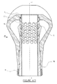
- FIG. 2 shows a muzzle brake according to the invention identical to the embodiment shown in Figure 1, but the jacket 5 is not smooth and has stripes 40 identical to those of the barrel 30 and extending them. In this case, it is necessary to orient said jacket so that the continuity of the scratches of the barrel 30 and of the jacket 5 is ensured.
- a key 25 carried by the muzzle brake 20 cooperates with a groove 51 formed for a part 51a in the barrel 30 positioned precisely with respect to the scratches of said barrel and for the other part 51b in the jacket 5 positioned precisely with respect to the scratches of said shirt.
- This key 25 is linked to the muzzle brake 20 by means of a screw 26 cooperating with said key and a tapping 28 formed in the muzzle brake 20.
- This configuration makes it possible to maintain the rotation of the projectile during its passage through the muzzle brake 20 which gives it better stabilization on the trajectory.
- FIG. 3 illustrates an alternative embodiment of the vents 54.
- These have an internal profile opening into the internal volume of the body 22, of ovoid shape whose major axis is parallel to the axis of the barrel YY 'and inclined by a angle ⁇ 3 with respect to the barrel axis YY 'substantially equal to the angle ⁇ 2 of the internal wall 22a of the body 22 with respect to said axis YY'.
- the major axis is between 15 and 40 mm and the minor axis is between 10 and 15 mm.
- the number of vents 54 must be as large as possible to allow most of the propellant gases to pass, but while ensuring that the minimum distance d4 between said vents is sufficient to withstand the pressure of the propellant gases.
- FIG. 4 illustrates another alternative embodiment of the vents 54. These are ovoid in shape and their major axis is perpendicular to the axis of the barrel YY 'and inclined at an angle ⁇ 3 relative to the axis YY' of the barrel substantially equal to the angle ⁇ 2 of the internal wall 22a of the body 22 relative to said axis YY '.
- the major axis is between 15 and 40 mm and the minor axis is between 10 and 15 mm.
- vents 54 must be as large as possible to allow most of the propellants, but ensuring that the minimum distance d4 between said vents is sufficient to withstand the pressure of the propellants.
- FIG. 5 illustrates another alternative embodiment of the vents 54 having a cylindrical profile 54a with a diameter comprised substantially between 10 and 20 mm opening on the internal side of the jacket 5 followed by a frustoconical profile 54b opening on the external side of said jacket in the internal volume of the body 22.
- the angle of inclination ⁇ 4 relative to the axis YY 'of the barrel 30 of the frustoconical part 54b is substantially equal to the inclination ⁇ 2 of the internal wall 22a of the body 22 relative to said axis YY '.
- the number of vents 54 must be as large as possible to allow most of the propellant gases to pass, but while ensuring that the distance d4 between said vents is sufficient to withstand the pressure of the propellant gases.
- This alternative embodiment of the vents 54 has the advantage of being easier to manufacture industrially.
- Figure 6 shows an alternative embodiment of the muzzle brake according to the invention in which the muzzle brake 20 and the tubular element 5 no longer form a single piece which can be obtained from a molding blank for example.
- This embodiment proves to be particularly economical, since it does not require the positioning of a jacket 5 relative to the muzzle brake 20 and relative to the barrel 30.
- Figure 7 shows a variant of the muzzle brake according to the invention in which the tubular element 5 is part of the same part as the barrel 30.
- the muzzle brake is oriented relative to the barrel 30 in a known manner by a non-key shown, but of the type described in relation to FIG. 1.
- the axial play between the tubular element 5 and the muzzle brake 20 is canceled by means of the face 6c of the tubular element 5 cooperating with the face 7c of the body 22 and with adjustment shims 11, the value of which is determined during assembly.
Landscapes
- Engineering & Computer Science (AREA)
- General Engineering & Computer Science (AREA)
- Braking Arrangements (AREA)
Abstract
Description
- Le domaine d'application de la présente invention est celui des freins de bouche pour canons de moyen ou gros calibre montés sur un affût ou une tourelle et en particulier ceux tirant des projectiles sous-calibrés.
- Pour réduire les efforts dus au tir transmis à l'affût ou à la tourelle, il est bien connu d'utiliser un frein de bouche à l'extrémité du canon qui crée un effort contraire à celui engendré par le tir. Cet effort est obtenu en canalisant une partie des gaz de propulsion vers des aubes comme cela est expliqué dans le brevet FR-A-510 111. Le frein de bouche est dans ce document constitué d'une pièce trouée vissée sur l'extrémité du canon et on vient rapporter sur ladite pièce une autre pièce formant aube.
- Dans le cas du tir de projectiles sous-calibrés à effet cinétique, du type flèche par exemple, il est fondamental d'obtenir une grande vitesse initiale du projectile (de l'ordre de 1300-1500 m.s-1) ce qui se traduit par des efforts induits sur l'arme très importants qu'il faut limiter.
- On connaît, pour cela, un frein de bouche dans le brevet français FR-A-2 507 765. Ce frein de bouche possède un diamètre intérieur très supérieur au calibre du canon de l'arme et il a un fort rendement énergétique (rapport entre l'énergie du recul de l'arme avec et sans frein de bouche), de l'ordre de 50 à 60%. Mais, dans le cas d'un tube de canon rayé, les sabots entraînant le projectile sous-calibré ont tendance à se détacher de celui-ci pendant leur passage dans le frein de bouche, ce phénomène étant d'autant plus important que l'angle des rayures du canon est élevé puisque la force centrifuge à laquelle sont soumises les différentes parties du sabot est plus importante. Cette ouverture des sabots entraîne des interférences entre le projectile et le frein de bouche conduisant à une déstabilisation du projectile et à une perte d'inefficacité.
- Pour éviter ce phénomène, il est de coutume d'augmenter le diamètre de passage dans le frein de bouche, mais cela diminue fortement son rendement ce qui accroît les efforts sur la structure porteuse de l'arme.
- On connaît d'autres modèles de frein de bouche du type multi-étages tel celui décrit dans le brevet US-A-5 119 716. Ceux-ci ont le désavantage de posséder une masse importante qui a pour effet d'entraîner un fort couple de déséquilibre sur le canon préjudiciable pour la rapidité et la précision de l'orientation de l'arme.
- Le but de la présente invention est de fournir un frein de bouche de rendement énergétique élevé, d'une masse limitée et capable de tirer les projectiles sous-calibrés sans leur transmettre une quelconque perturbation.
- L'invention a donc pour objet un frein de bouche pour canon de moyen ou de gros calibre présentant un corps dont les dimensions intérieures sont très supérieures au calibre du canon, muni d'au moins un étage de deux ouïes prolongées par des aubes sur lesquelles s'appliquent les gaz propulsifs pour créer une force de sens contraire à celle engendrée par ces gaz, caractérisé en ce qu'il comporte un élément tubulaire prolongeant l'extrémité libre du canon engagé dans le corps du frein de bouche, percé d'une pluralité d'évents qui dirigent les gaz propulsifs vers les aubes, le diamètre interne d1 de cet élément étant compris sensiblement entre le calibre d2 du canon et le diamètre d3 de fond de rayure du canon.
- Selon une caractéristique de l'invention, la paroi interne de l'élément tubulaire est lisse, et son diamètre intérieur d1 est égal au calibre d2 du canon.
- Selon une caractéristique de l'invention, la paroi interne de l'élément tubulaire est lisse et son diamètre intérieur d1 est égal au diamètre d3 de fond de rayure du canon.
- Selon une caractéristique de l'invention, la paroi interne de l'élément tubulaire est munie de rayures identiques à celles du canon.
- Selon une autre caractéristique de l'invention, les évents présentent un profil interne cylindrique de diamètre compris entre 10 et 20 mm et incliné d'un angle α1 par rapport à l'axe du canon, sensiblement égal à l'inclinaison α2 de la paroi interne du corps par rapport audit axe du canon.
- Selon une autre caractéristique de l'invention, les évents présentent un profil interne ovoïde de grand axe compris sensiblement entre 15 et 40 mm et de petit axe compris entre 10 et 15 mm, incliné d'un angle α3 par rapport à l'axe du canon, sensiblement égal à l'inclinaison α2 de la paroi interne du corps du frein de bouche par rapport à l'axe dudit canon.
- Selon encore une autre caractéristique de l'invention, les évents présentent un profil cylindrique de diamètre compris sensiblement entre 10 et 20 mm débouchant du côté interne de l'élément tubulaire, et un profil tronconique débouchant du côté externe dudit élément tubulaire avec un angle d'inclinaison α4 par rapport à l'axe du canon sensiblement égal à l'inclinaison α2 de la paroi interne du corps par rapport audit axe du canon.
- Selon encore une autre caractéristique de l'invention, l'élément tubulaire se présente sous la forme d'une chemise d'épaisseur comprise entre 5 et 10 mm réalisée en acier ayant une limite élastique d'environ 1 000 MPa.
- Selon encore une autre caractéristique de l'invention, la chemise est centrée sur l'axe du canon par l'intermédiaire de portées de guidage aux extrémités coopérant avec des portées de réception pratiquées sur la paroi interne du corps.
- Selon une autre caractéristique de l'invention, l'élément tubulaire est immobilisé par rapport au corps du frein de bouche par un moyen de blocage constitué par exemple par une clavette.
- Selon une autre caractéristique de l'invention, l'élément tubulaire est orienté et immobilisé en rotation par rapport au canon par une clavette vissée dans le corps de frein de bouche coopérant avec une rainure pratiquée dans l'élément tubulaire et une autre rainure pratiquée dans le canon.
- Selon une autre caractéristique de l'invention, l'élément tubulaire est immobilisé en translation par rapport au canon à l'aide de deux épaulements pratiqués l'un à l'extrémité avant dudit élément et l'autre à la partie avant du corps de frein de bouche, des cales de réglage étant éventuellement logées entre ces deux épaulements.
- Selon encore une autre caractéristique de l'invention, l'élément tubulaire et le corps du frein de bouche peuvent être réalisés en une seule pièce issue d'un ébauché de moulage par exemple.
- Selon encore une autre caractéristique de l'invention, le canon et l'élément tubulaire ne forment qu'une seule pièce.
- Un premier avantage du frein de bouche suivant l'invention réside dans son rendement énergétique important et donc dans la possibilité offerte au système d'arme de tirer des munitions à haute énergie.
- Un autre avantage de ce frein de bouche est de pouvoir tirer un projectile sous-calibré sans qu'il n'y ait d'interférences entre eux.
- Un autre avantage de l'invention réside dans le fait d'offrir un frein de bouche de masse réduite facilitant le pointage de l'arme.
- D'autres caractéristiques et avantages de l'invention ressortiront plus clairement de la description donnée ci-après à titre indicatif en relation avec des dessins sur lesquels :
- la figure 1 représente une coupe axiale d'un frein de bouche équipé d'une chemise lisse,
- la figure 2 représente une coupe axiale d'un frein de bouche équipé d'une chemise rayée,
- la figure 3 illustre une première variante de réalisation des évents,
- la figure 4 illustre une seconde variante de réalisation des évents,
- La figure 5 illustre une troisième variante de réalisation des évents,
- La figure 6 représente une coupe d'un frein de bouche réalisé en une seule pièce,
- La figure 7 représente une coupe d'un frein de bouche où les évents sont percés directement en bout du canon.
- La figure 1 représente un mode de réalisation de l'invention d'un frein de bouche, dit simple étage, c'est à dire ne disposant que d'une seule rangée d'aubes et communément appelé frein de bouche "tulipe". Ce frein de bouche 20 se compose d'une partie cylindrique 21 liée au tube de canon 30 par une liaison filetée 8 freinée par un système de contre-écrou 9 et orientée de façon connue par une clavette (non représentée) par rapport au canon 30 et d'un corps 22 muni d'aubes 22b sur lesquelles viennent s'appuyer les gaz propulsifs pour engendrer une force de sens contraire à celle engendrée par le tir de la munition, d'ouïes 22e pour détendre ces gaz propulsifs et les éjecter vers l'extérieur et d'un orifice de sortie du projectile 22f.
- La partie interne du corps est composée d'une partie tronconique divergente 22a suivie par une partie convergente 22b formant les aubes et d'une surface 22c sensiblement perpendiculaire à l'axe YY' du canon, la partie divergente 22a et la partie convergente 22b sont reliées par une surface courbe 22d. La surface externe 22h du corps 22 est sensiblement parrallèle aux surfaces internes dudit corps.
- Pour des raisons de tenue mécanique du corps 22, un renfort 22g formant poutre est placé à l'avant dudit corps.
- Le fonctionnement d'un tel frein de bouche est le suivant : lors du tir de la munition, le projectile parcourt le canon 30 puis passe dans dans le corps 22 du frein de bouche 20 et ressort par l'orifice de sortie 22f. Le tir de la munition a pour effet, par suite de la conservation de la quantité de mouvement, de faire reculer le canon vers l'arrière et d'engendrer des efforts importants sur la structure porteuse du canon qui peut être un affût ou une tourelle. Le rôle du frein de bouche 20 est de limiter les efforts engendrés sur la structure porteuse du canon. Pour cela, une grande partie des gaz propulsifs est dirigée grâce à la surface divergente 22a vers les aubes 22b créant ainsi une force aérodynamique de sens contraire à celle engendrée par le tir de la munition. Les gaz propulsifs peuvent ensuite s'échapper par les ouïes 22e.
- La forme interne du frein de bouche 20 lui permet d'avoir un grand rendement énergétique, de l'ordre de 50 à 60%, celui-ci étant le rapport de l'énergie de recul du canon avec et sans frein de bouche.
- L'inconvénient du frein de bouche tel que décrit ci-dessus apparaît nettement pour le tir de munitions sous-calibrées composées d'un noyau de faible diamètre qui est propulsé dans un canon de plus fort calibre par l'intermédiaire de sabots. Ces sabots n'ont qu'une fonction de balistique intérieure et sont détachés à la sortie du canon soit par des forces aérodynamiques qui s'appliquent sur eux soit par la force centrifuge qui a tendance à les écarter du noyau. La forme particulièrement évasée de la paroi interne du frein de bouche 20 laisse la liberté aux sabots de commencer à se détacher du noyau par l'un ou l'autre des phénomènes susdits et d'entrer en interférence avec l'orifice de sortie 22f. Cela induit des efforts parasites sur le noyau entraînant sa déstabilisation et une détérioration du frein de bouche 20.
- C'est pourquoi, pour pallier cet inconvénient, il est proposé, suivant l'invention, d'engager dans le corps 22 du frein de bouche 20 une chemise 5 prolongeant l'extrémité libre du canon 30 et percée d'une pluralité d'évents 54. La paroi interne de la chemise 5 est lisse et son diamètre d1 est égal au diamètre d2 du canon 30 quand celui-ci est lisse ou égal au diamètre d3 de fond de rayure du canon quand celui-ci est rayé.
- La chemise 5 est centrée par rapport au canon 30 et au frein de bouche 20 par l'intermédiaire des portées 6a, 6b de la chemise 5 coopérant avec les portées 7a, 7b pratiquées dans la paroi interne du corps 22 et par l'intermédiaire de la portée 6d de la chemise 5 coopérant avec la portée 7d pratiquée dans le canon 30.
- La chemise 5 est aussi positionnée axialement sans jeu entre le frein de bouche 20 et le canon 30 par le biais de la face 6e de la chemise 5 coopérant avec la tranche avant 31 du canon d'une part, et par le biais de la face 6c de la chemise 5 coopérant avec la face 7c du corps 22 et de cales de réglages 11 dont la valeur est déterminée au montage d'autre part.
- La chemise 5 est immobilisée en rotation par rapport au frein de bouche 20 par l'intermédiaire d'une clavette 25 engagée dans une rainure 27 dudit frein de bouche et coopérant avec une rainure 51 pratiquée dans la chemise 5. Cette clavette 25 est liée au frein de bouche 20 par l'intermédiaire d'une vis 26 coopérant avec ladite clavette et d'un taraudage 28 pratiqué dans le frein de bouche 20.
- Un chanfrein 29 réalisé sur la face interne de la chemise 5 du côté en contact avec le canon 30 facilite le passage du sabot de la munition dans ladite chemise.
- La chemise 5 présente une épaisseur moyenne de 5 à 10 mm et est réalisée dans un matériau ayant une limite élastique d'environ 1 000 MPa.
- La chemise 5 est percée d'évents 54, qui débouchent dans le volume interne du corps 22, de forme cylindrique dont l'angle α1 par rapport à l'axe YY' du canon 30 est sensiblement égal à l'angle α2 de la paroi 22a du corps 22 par rapport audit axe YY'. Le diamètre des évents 54 est compris entre 10 et 20 mm. Le nombre des évents 54 doit être le plus grand possible pour laisser passer la plus grande partie des gaz propulsifs, mais en s'assurant que la distance d4 entre lesdits évents soit suffisante pour résister à la pression des gaz propulsifs.
- Avec le frein de bouche 20 suivant l'invention, les sabots du projectile sous-calibré restent liés au noyau lors de leur passage dans le frein de bouche 20 grâce à la chemise 5 qui est de même diamètre d2 ou d3 que le canon 30. Les sabots se détachent librement du noyau à la sortie du frein de bouche 20 n'engendrant ainsi aucun effet parasite sur le noyau ou endommagement du frein de bouche 20. Les gaz propulsifs sont dirigés par les évents 54 vers les aubes 22b pour engendrer une force de sens contraire à celle induite par le tir.
- La figure 2 représente un frein de bouche selon l'invention identique au mode de réalisation représenté à la figure 1, mais la chemise 5 n'est pas lisse et possède des rayures 40 identiques à celles du canon 30 et les prolongeant. Dans ce cas, il est nécessaire d'orienter ladite chemise afin que la continuité des rayures du canon 30 et de la chemise 5 soit assurée. Une clavette 25 portée par le frein de bouche 20 coopère avec une rainure 51 pratiquée pour une partie 51a dans le canon 30 positionnée de façon précise par rapport aux rayures dudit canon et pour l'autre partie 51b dans la chemise 5 positionnée de façon précise par rapport aux rayures de ladite chemise. Cette clavette 25 est liée au frein de bouche 20 par l'intermédiaire d'une vis 26 coopérant avec ladite clavette et d'un taraudage 28 pratiqué dans le frein de bouche 20.
- Cette configuration permet d'entretenir la rotation du projectile pendant son passage dans le frein de bouche 20 ce qui lui confère une meilleure stabilisation sur trajectoire.
- La figure 3 illustre une variante de réalisation des évents 54. Ceux-ci présentent un profil interne débouchant dans le volume interne du corps 22, de forme ovoïde dont le grand axe est parallèle à l'axe du canon YY' et incliné d'un angle α3 par rapport à l'axe de canon YY' sensiblement égal à l'angle α2 de la paroi interne 22a du corps 22 par rapport audit axe YY'. Pour chaque évent, le grand axe est compris entre 15 et 40 mm et le petit axe est compris entre 10 et 15 mm. Le nombre des évents 54 doit être le plus grand possible pour laisser passer la plus grande partie des gaz propulsifs, mais en s'assurant que la distance minimale d4 entre lesdits évents soit suffisante pour résister à la pression des gaz propulsifs.
- La figure 4 illustre une autre variante de réalisation des évents 54. Ceux-ci sont de forme ovoïde et leur grand axe est perpendiculaire à l'axe du canon YY' et incliné d'un angle α3 par rapport à l'axe YY' du canon sensiblement égal à l'angle α2 de la paroi interne 22a du corps 22 par rapport audit axe YY'.
- Pour chaque évent, le grand axe est compris entre 15 et 40 mm et le petit axe est compris entre 10 et 15 mm.
- Le nombre des évents 54 doit être le plus grand possible pour laisser passer la plus grande partie des gaz propulsifs, mais en s'assurant que la distance minimale d4 entre lesdits évents soit suffisante pour résister à la pression des gaz propulsifs.
- La figure 5 illustre une autre variante de réalisation des évents 54 présentant un profil cylindrique 54a de diamètre compris sensiblement entre 10 et 20 mm débouchant du côté interne de la chemise 5 suivi d'un profil tronconique 54b débouchant du côté externe de ladite chemise dans le volume interne du corps 22. L'angle d'inclinaison α4 par rapport à l'axe YY' du canon 30 de la partie tronconique 54b est sensiblement égal à l'inclinaison α2 de la paroi interne 22a du corps 22 par rapport audit axe YY'. Le nombre des évents 54 doit être le plus grand possible pour laisser passer la plus grande partie des gaz propulsifs, mais en s'assurant que la distance d4 entre lesdits évents soit suffisante pour résister à la pression des gaz propulsifs.
- Cette variante de réalisation des évents 54 présente l'avantage d'être plus facilement fabricable industriellement.
- La figure 6 présente une variante de réalisation du frein de bouche suivant l'invention dans laquelle le frein de bouche 20 et l'élément tubulaire 5 ne forment plus qu'une seule pièce qui peut être issue d'un ébauché de moulage par exemple. Cette réalisation s'avère particulièrement économique, car elle ne nécessite pas le positionnement d'une chemise 5 par rapport au frein de bouche 20 et par rapport au canon 30.
- La figure 7 présente une variante du frein de bouche suivant l'invention dans laquelle l'élément tubulaire 5 fait partie de la même pièce que le canon 30. Le frein de bouche est orienté par rapport au canon 30 de façon connue par une clavette non représentée, mais du type de celle décrite en relation avec la figure 1. Le jeu axial entre l'élément tubulaire 5 et le frein de bouche 20 est annulé par le biais de la face 6c de l'élément tubulaire 5 coopérant avec la face 7c du corps 22 et avec des cales de réglages 11 dont la valeur est déterminée au montage.
Claims (14)
- Frein de bouche pour canon de moyen ou gros calibre, présentant un corps dont les dimensions intérieures sont très supérieures au calibre du canon, muni d'au moins un étage de deux ouïes (22e) prolongées par des aubes (22b) sur lesquelles s'appliquent les gaz propulsifs pour créer une force de sens contraire à celle engendrée par ces gaz, caractérisé en ce qu'il comporte un élément tubulaire (5) prolongeant l'extrémité libre du canon, engagé dans le corps (22) et percé d'une pluralité d'évents (54) dirigeant les gaz propulsifs vers les aubes (22b), le diamètre interne d1 de cet élément tubulaire étant compris sensiblement entre le calibre d2 et le diamètre d3 de fond de rayure du canon.
- Frein de bouche selon la revendication 1, caractérisé en ce que la paroi interne de l'élément tubulaire (5) est lisse, le diamètre d1 étant égal au diamètre d2.
- Frein de bouche selon la revendication 1, caractérisé en ce que la paroi interne de l'élément tubulaire (5) est lisse, le diamètre d1 étant égal au diamètre d3.
- Frein de bouche selon la revendication 1, caractérisé en ce que la paroi interne de l'élément tubulaire (5) est munie de rayures identiques à celles du canon (30).
- Frein de bouche suivant l'une quelconque des revendications 1 à 4, caractérisé en ce que les évents (54) présentent un profil interne cylindrique de diamètre compris entre environ 10 et 20 mm et incliné d'un angle α1 par rapport à l'axe YY' du canon (30) sensiblement égal à l'inclinaison α2 de la paroi interne (22a) du corps (22) par rapport audit axe YY'.
- Frein de bouche suivant l'une quelconque des revendications 1 à 4, caractérisé en ce que les évents (54) présentent un profil interne ovoïde de grand axe compris sensiblement entre 15 et 40 mm et de petit axe compris sensiblement entre 10 et 15 mm, incliné d'un angle α3 par rapport à l'axe YY' du canon (30) sensiblement égal à l'inclinaison α2 de la paroi interne (22a) du corps (22) par rapport audit axe YY'.
- Frein de bouche suivant l'une quelconque des revendications 1 à 4, caractérisé en ce que les évents (54) présentent un profil cylindrique (54a) de diamètre compris sensiblement entre 10 et 20 mm débouchant du côté interne de l'élément tubulaire (5), et un profil tronconique (54b) débouchant du côté externe dudit élément tubulaire avec un angle d'inclinaison α4 par rapport à l'axe YY' du canon (30) sensiblement égal à l'inclinaison α2 de la paroi interne du corps (22) par rapport audit axe YY'.
- Frein de bouche suivant l'une quelconque des revendications précédentes, caractérisé en ce que l'élément tubulaire (5) se présente sous la forme d'une chemise d'épaisseur comprise entre 5 et 10 mm environ réalisée en un acier ayant une limite élastique d'environ 1 000 MPa.
- Frein de bouche suivant la revendication 8, caractérisé en ce que la chemise est centrée sur l'axe YY' du canon (30) par l'intermédiaire de portées de guidage (7a, 7b, 7d) situées aux extrémités coopérant avec des portées de réception (6a, 6b, 6d) pratiquées sur la paroi interne du corps (22).
- Frein de bouche suivant l'une quelconque des revendications précédentes, caractérisé en ce que l'élément tubulaire (5) est immobilisé par rapport au corps (22) par un moyen de blocage (25) constitué par exemple par une clavette.
- Frein de bouche suivant la revendication 10, caractérisé en ce que l'élément tubulaire (5) est orienté et immobilisé en rotation par rapport au canon (30) par une clavette (25) vissée dans le corps (22) coopérant avec une rainure (51a) pratiquée dans l'élément tubulaire et une autre rainure (51b) pratiquée dans canon (30).
- Frein de bouche suivant l'une quelconque des revendications 1 à 11, caractérisé en ce que l'élément tubulaire (5) est immobilisé en translation par rapport au canon (30) à l'aide de deux épaulements (7c, 6c) et (6d, 31) pratiqués l'un à l'extrémité avant dudit élément et l'autre à la partie avant du corps (22), des cales de réglage (11) étant éventuellement logées entre ces deux épaulements.
- Frein de bouche suivant l'une quelconque des revendications 1 à 9, caractérisé en ce que l'élément tubulaire (5) et le corps (22) sont réalisés en une seule pièce.
- Frein de bouche suivant l'une quelconque des revendications 1 à 8, caractérisé en ce que l'élément tubulaire (5) et le canon (30) ne forment qu'une seule pièce.
Applications Claiming Priority (2)
| Application Number | Priority Date | Filing Date | Title |
|---|---|---|---|
| FR9500492 | 1995-01-18 | ||
| FR9500492A FR2729464A1 (fr) | 1995-01-18 | 1995-01-18 | Frein de bouche pour canons de moyen ou de gros calibre |
Publications (2)
| Publication Number | Publication Date |
|---|---|
| EP0723131A1 true EP0723131A1 (fr) | 1996-07-24 |
| EP0723131B1 EP0723131B1 (fr) | 1999-09-08 |
Family
ID=9475214
Family Applications (1)
| Application Number | Title | Priority Date | Filing Date |
|---|---|---|---|
| EP96400088A Expired - Lifetime EP0723131B1 (fr) | 1995-01-18 | 1996-01-15 | Frein de bouche pour canons de moyen ou de gros calibre |
Country Status (5)
| Country | Link |
|---|---|
| US (1) | US5675107A (fr) |
| EP (1) | EP0723131B1 (fr) |
| DE (1) | DE69604097T2 (fr) |
| FR (1) | FR2729464A1 (fr) |
| ZA (1) | ZA96353B (fr) |
Cited By (4)
| Publication number | Priority date | Publication date | Assignee | Title |
|---|---|---|---|---|
| EP1055899A1 (fr) * | 1999-05-27 | 2000-11-29 | Giat Industries | Dispositif de fixation d'un frein de bouche sur le tube d'une arme |
| US6308608B1 (en) | 1998-08-30 | 2001-10-30 | Moshe Eisenman | Dust suppression |
| WO2003008892A1 (fr) * | 2001-07-19 | 2003-01-30 | Ordnance Development And Engineering Company Of S Ingapore (1996) Pte Ltd. | Diffuseur de souffle |
| US8695475B2 (en) | 2010-05-06 | 2014-04-15 | Rheinmetall Waffe Munition Gmbh | Signature-reduced muzzle brake |
Families Citing this family (33)
| Publication number | Priority date | Publication date | Assignee | Title |
|---|---|---|---|---|
| US6339992B1 (en) * | 1999-03-11 | 2002-01-22 | Rocktek Limited | Small charge blasting apparatus including device for sealing pressurized fluids in holes |
| RU2151994C1 (ru) * | 1999-05-31 | 2000-06-27 | Силаков Валерий Андреевич | Ствольная насадка к многоствольному оружию |
| USD435884S1 (en) | 2000-07-07 | 2001-01-02 | Dye Products, Inc. | Paintball gun barrel muzzle |
| RU2216703C2 (ru) * | 2000-08-10 | 2003-11-20 | 3 Центральный научно-исследовательский институт Министерства обороны Российской Федерации | Устройство для уменьшения избыточного давления при выстреле и стабилизации ствола огнестрельного оружия |
| RU2191965C1 (ru) * | 2001-08-21 | 2002-10-27 | Кузнецов Александр Константинович | Устройство для торможения отдачи стрелкового оружия |
| RU2228504C1 (ru) * | 2003-01-30 | 2004-05-10 | Государственное учреждение "Российский научно-исследовательский институт импульсных тепловых машин" Министерства образования РФ | Надульное устройство тмт-2 |
| RU2253817C1 (ru) * | 2004-02-16 | 2005-06-10 | Кузнецов Александр Константинович | Устройство для торможения отдачи стрелкового оружия |
| RU2266507C1 (ru) * | 2004-03-30 | 2005-12-20 | Открытое акционерное общество "Завод им. В.А. Дегтярёва" | Дульный тормоз |
| FR2870331B1 (fr) * | 2004-05-17 | 2006-06-30 | Giat Ind Sa | Frein de bouche pour arme |
| RU2278341C2 (ru) * | 2005-03-15 | 2006-06-20 | Александр Владимирович Глухов | Глушитель |
| RU2279622C1 (ru) * | 2005-04-05 | 2006-07-10 | Игорь Фёдорович Усов | Устройство для снижения отдачи и шума при стрельбе из оружия с нарезными стволами |
| US20100269387A1 (en) * | 2006-02-28 | 2010-10-28 | Cornell Drajan | Muzzle Break |
| DE102007024515A1 (de) | 2007-05-24 | 2008-11-27 | Rheinmetall Waffe Munition Gmbh | Vorrichtung und Verfahren zur Befestigung einer Mündungsbremse an einem Waffenrohr |
| US7895787B1 (en) * | 2008-01-11 | 2011-03-01 | Andry Mark L | Porting feature for firearm |
| AU2013240588A1 (en) * | 2012-01-06 | 2014-08-21 | Ra Brands, L.L.C. | Cancellation muzzle brake assembly |
| USD694355S1 (en) * | 2012-08-20 | 2013-11-26 | Karl Hormann | Muzzle brake |
| US9593900B2 (en) * | 2013-11-19 | 2017-03-14 | Stephen Paul Vossler | Muzzle brake |
| US9207034B2 (en) * | 2014-01-08 | 2015-12-08 | Rock River Arms, Inc. | Muzzle brake for firearm |
| US9541345B2 (en) | 2014-03-18 | 2017-01-10 | Steven H. Schwartzkopf | Recoil and muzzle blast controller for firearms |
| US9417024B2 (en) * | 2014-09-25 | 2016-08-16 | Spike's Tactical, Llc | Asymmetric muzzle compensator for firearm |
| US10274278B2 (en) * | 2015-01-16 | 2019-04-30 | Surefire, Llc | Firearm attachment |
| US9689636B2 (en) * | 2015-02-03 | 2017-06-27 | Edward Rigor Randall | Recoil reducing muzzle brake |
| US10466004B2 (en) * | 2015-08-11 | 2019-11-05 | Drew Nolle Walker | Optimized flow compensator |
| US9903678B2 (en) * | 2015-08-26 | 2018-02-27 | John SHERRILL | Method of manufacturing a diffuser muzzle brake |
| US11280572B2 (en) | 2016-03-10 | 2022-03-22 | James Norman Griffitts | Barrel stabilizing and recoil reducing muzzle brake with guiding ribs |
| US10422603B2 (en) | 2016-03-10 | 2019-09-24 | James Norman Griffitts | Barrel stabilizing and recoil reducing muzzle brake |
| US10816300B2 (en) | 2016-03-10 | 2020-10-27 | James Norman Griffitts | Barrel stabilizing and recoil reducing muzzle brake |
| EP3583374A4 (fr) * | 2017-02-15 | 2021-01-06 | James Norman Griffitts | Frein de bouche de canon de réduction de recul et de stabilisation de tube d'arme |
| US10801797B2 (en) * | 2017-10-11 | 2020-10-13 | Justin Peijay Cheng | Muzzle device |
| US10809033B2 (en) | 2017-11-29 | 2020-10-20 | Michael P. Tindal | Firearm compensator |
| US11112201B2 (en) | 2019-07-29 | 2021-09-07 | Sturm, Ruger & Company, Inc. | Ported barrel system for firearms |
| US12163750B2 (en) | 2021-02-12 | 2024-12-10 | James Norman Griffitts | Sound suppressor with adapter for use with muzzle accessory |
| US20250093119A1 (en) * | 2023-09-20 | 2025-03-20 | Michael Arthur Green, Jr. | Firearm and a method for reducing firearm barrel rise |
Citations (6)
| Publication number | Priority date | Publication date | Assignee | Title |
|---|---|---|---|---|
| US3141376A (en) * | 1955-06-13 | 1964-07-21 | George M Chinn | Flame-out eliminator |
| US3492912A (en) * | 1966-09-01 | 1970-02-03 | Ashbrook Clifford L | Recoil controlling device |
| US4307652A (en) * | 1979-11-02 | 1981-12-29 | Leonard Witt | Muzzle-guard for firearms |
| FR2507765A1 (fr) * | 1981-06-16 | 1982-12-17 | France Etat | Procede et dispositif de tir d'une munition fleche a l'aide d'un tube raye |
| US4545285A (en) * | 1982-06-15 | 1985-10-08 | Mclain Clifford E | Matched expansion muzzle brake |
| US5119716A (en) * | 1990-08-11 | 1992-06-09 | Rheinmetall Gmbh | Muzzle brake for a large caliber tubular weapon |
Family Cites Families (6)
| Publication number | Priority date | Publication date | Assignee | Title |
|---|---|---|---|---|
| CH46859A (de) * | 1909-04-10 | 1910-05-02 | Jakob Wertli | Geschützrohr |
| US1363058A (en) * | 1921-02-10 | 1920-12-21 | T F Shanahn | Car construction |
| FR715769A (fr) * | 1930-04-26 | 1931-12-09 | Anciens Ets Skoda | Frein pour orifice de bouche à feu |
| FR772162A (fr) * | 1934-04-20 | 1934-10-24 | Bofors Ab | Frein de bouche pour tubes de canon |
| FR812680A (fr) * | 1936-01-21 | 1937-05-14 | Brev Etudes Soc | Nouveaux perfectionnements aux armes à feu ou autres |
| US5333529A (en) * | 1993-01-08 | 1994-08-02 | Rott & Company | Convertible muzzle brake |
-
1995
- 1995-01-18 FR FR9500492A patent/FR2729464A1/fr active Granted
-
1996
- 1996-01-15 DE DE69604097T patent/DE69604097T2/de not_active Expired - Lifetime
- 1996-01-15 EP EP96400088A patent/EP0723131B1/fr not_active Expired - Lifetime
- 1996-01-16 US US08/586,974 patent/US5675107A/en not_active Expired - Fee Related
- 1996-01-17 ZA ZA96353A patent/ZA96353B/xx unknown
Patent Citations (6)
| Publication number | Priority date | Publication date | Assignee | Title |
|---|---|---|---|---|
| US3141376A (en) * | 1955-06-13 | 1964-07-21 | George M Chinn | Flame-out eliminator |
| US3492912A (en) * | 1966-09-01 | 1970-02-03 | Ashbrook Clifford L | Recoil controlling device |
| US4307652A (en) * | 1979-11-02 | 1981-12-29 | Leonard Witt | Muzzle-guard for firearms |
| FR2507765A1 (fr) * | 1981-06-16 | 1982-12-17 | France Etat | Procede et dispositif de tir d'une munition fleche a l'aide d'un tube raye |
| US4545285A (en) * | 1982-06-15 | 1985-10-08 | Mclain Clifford E | Matched expansion muzzle brake |
| US5119716A (en) * | 1990-08-11 | 1992-06-09 | Rheinmetall Gmbh | Muzzle brake for a large caliber tubular weapon |
Cited By (7)
| Publication number | Priority date | Publication date | Assignee | Title |
|---|---|---|---|---|
| US6308608B1 (en) | 1998-08-30 | 2001-10-30 | Moshe Eisenman | Dust suppression |
| EP1055899A1 (fr) * | 1999-05-27 | 2000-11-29 | Giat Industries | Dispositif de fixation d'un frein de bouche sur le tube d'une arme |
| FR2794229A1 (fr) * | 1999-05-27 | 2000-12-01 | Giat Ind Sa | Dispositif de fixation d'un frein de bouche sur le tube d'une arme |
| US6450079B1 (en) | 1999-05-27 | 2002-09-17 | Giat Industries | Device for affixing a muzzle brake to a weapon barrel |
| WO2003008892A1 (fr) * | 2001-07-19 | 2003-01-30 | Ordnance Development And Engineering Company Of S Ingapore (1996) Pte Ltd. | Diffuseur de souffle |
| US6880444B2 (en) | 2001-07-19 | 2005-04-19 | Ordance Development And Engineering Company Of Singapore | Blast diffuser |
| US8695475B2 (en) | 2010-05-06 | 2014-04-15 | Rheinmetall Waffe Munition Gmbh | Signature-reduced muzzle brake |
Also Published As
| Publication number | Publication date |
|---|---|
| FR2729464B1 (fr) | 1997-03-07 |
| ZA96353B (en) | 1997-01-03 |
| US5675107A (en) | 1997-10-07 |
| EP0723131B1 (fr) | 1999-09-08 |
| DE69604097D1 (de) | 1999-10-14 |
| DE69604097T2 (de) | 2000-01-20 |
| FR2729464A1 (fr) | 1996-07-19 |
Similar Documents
| Publication | Publication Date | Title |
|---|---|---|
| EP0723131B1 (fr) | Frein de bouche pour canons de moyen ou de gros calibre | |
| CA2558031C (fr) | Balle de chasse a bague d'expansion | |
| EP1600723B1 (fr) | Frein de bouche pour arme | |
| FR2795170A1 (fr) | Balle a fleche interne portee | |
| CH634142A5 (fr) | Mecanisme de lancement d'un projectile sous-calibre. | |
| FR2764056A1 (fr) | Frein de bouche pour tube d'arme | |
| FR2599828A1 (fr) | Munition de petit ou moyen calibre a efficacite amelioree et portee limitee, en particulier pour la chasse | |
| EP0737298B1 (fr) | Balle de chasse a fleche telescopee, comportant un sous-projectile associe a un lanceur | |
| FR2462688A1 (fr) | Projectile muni de conduits d'ecoulement provoquant une giration | |
| FR2685468A1 (fr) | Tube douille pour grenade a fusil pouvant retenir les fragments de la balle. | |
| FR2859523A1 (fr) | Balle de chasse a trainee aerodynamique reduite | |
| EP0048644B1 (fr) | Projectile empenné du type flèche | |
| EP0728293B1 (fr) | Balle de chasse a double penetration et a portee reduite | |
| CA2146443C (fr) | Sabot a separation controlee des elements pour projectiles sous-calibres | |
| EP0279715A1 (fr) | Arme à feu pour tirer des munitions sans douilles et munitions pour une telle arme | |
| FR2759453A1 (fr) | Projectile a cage de propulsion sous-calibre | |
| FR2512541A1 (fr) | Projectile d'exercice pour armes a tir tendu | |
| CH651382A5 (fr) | Charge creuse. | |
| WO1991002211A1 (fr) | Perfectionnements apportes aux munitions destinees a etre tirees par une arme a canon lisse | |
| FR2718839A1 (fr) | Frein de bouche pour arme de moyen ou gros calibre. | |
| FR2666144A1 (fr) | Projectile sous-calibre avec cage de propulsion. | |
| EP0258125B1 (fr) | Balle de chasse sous-calibrée de type flèche à efficacité terminale accrue sur cibles molles | |
| FR2465182A1 (fr) | Reducteur de calibre pour armes a percussion centrale | |
| CA2179066C (fr) | Balle de chasse a fleche telescopee, comportant un sous-projectile associe a un lanceur | |
| FR2574921A2 (fr) | Dispositif de projectile monopiece, lance par arme portative |
Legal Events
| Date | Code | Title | Description |
|---|---|---|---|
| PUAI | Public reference made under article 153(3) epc to a published international application that has entered the european phase |
Free format text: ORIGINAL CODE: 0009012 |
|
| AK | Designated contracting states |
Kind code of ref document: A1 Designated state(s): BE DE GB IT |
|
| 17P | Request for examination filed |
Effective date: 19960917 |
|
| GRAG | Despatch of communication of intention to grant |
Free format text: ORIGINAL CODE: EPIDOS AGRA |
|
| GRAG | Despatch of communication of intention to grant |
Free format text: ORIGINAL CODE: EPIDOS AGRA |
|
| GRAH | Despatch of communication of intention to grant a patent |
Free format text: ORIGINAL CODE: EPIDOS IGRA |
|
| 17Q | First examination report despatched |
Effective date: 19990216 |
|
| GRAH | Despatch of communication of intention to grant a patent |
Free format text: ORIGINAL CODE: EPIDOS IGRA |
|
| GRAA | (expected) grant |
Free format text: ORIGINAL CODE: 0009210 |
|
| AK | Designated contracting states |
Kind code of ref document: B1 Designated state(s): BE DE GB IT |
|
| RIN1 | Information on inventor provided before grant (corrected) |
Inventor name: DUPUY, REGIS Inventor name: BRUNET, NICOLAS Inventor name: LEDYS, FRANCIS |
|
| ITF | It: translation for a ep patent filed | ||
| REF | Corresponds to: |
Ref document number: 69604097 Country of ref document: DE Date of ref document: 19991014 |
|
| PLBI | Opposition filed |
Free format text: ORIGINAL CODE: 0009260 |
|
| PLBF | Reply of patent proprietor to notice(s) of opposition |
Free format text: ORIGINAL CODE: EPIDOS OBSO |
|
| 26 | Opposition filed |
Opponent name: RHEINMETALL W & M GMBH PATENTABTEILUNG Effective date: 20000527 |
|
| PLBF | Reply of patent proprietor to notice(s) of opposition |
Free format text: ORIGINAL CODE: EPIDOS OBSO |
|
| REG | Reference to a national code |
Ref country code: GB Ref legal event code: IF02 |
|
| PLBO | Opposition rejected |
Free format text: ORIGINAL CODE: EPIDOS REJO |
|
| APAC | Appeal dossier modified |
Free format text: ORIGINAL CODE: EPIDOS NOAPO |
|
| APBQ | Date of receipt of statement of grounds of appeal recorded |
Free format text: ORIGINAL CODE: EPIDOSNNOA3O |
|
| APAA | Appeal reference recorded |
Free format text: ORIGINAL CODE: EPIDOS REFN |
|
| APAH | Appeal reference modified |
Free format text: ORIGINAL CODE: EPIDOSCREFNO |
|
| APBU | Appeal procedure closed |
Free format text: ORIGINAL CODE: EPIDOSNNOA9O |
|
| PLBN | Opposition rejected |
Free format text: ORIGINAL CODE: 0009273 |
|
| STAA | Information on the status of an ep patent application or granted ep patent |
Free format text: STATUS: OPPOSITION REJECTED |
|
| 27O | Opposition rejected |
Effective date: 20051129 |
|
| REG | Reference to a national code |
Ref country code: GB Ref legal event code: 732E Free format text: REGISTERED BETWEEN 20090625 AND 20090701 |
|
| PGFP | Annual fee paid to national office [announced via postgrant information from national office to epo] |
Ref country code: IT Payment date: 20111223 Year of fee payment: 17 |
|
| PGFP | Annual fee paid to national office [announced via postgrant information from national office to epo] |
Ref country code: GB Payment date: 20121224 Year of fee payment: 18 |
|
| PGFP | Annual fee paid to national office [announced via postgrant information from national office to epo] |
Ref country code: BE Payment date: 20121221 Year of fee payment: 18 Ref country code: DE Payment date: 20121226 Year of fee payment: 18 |
|
| BERE | Be: lapsed |
Owner name: *GIAT INDUSTRIES Effective date: 20140131 |
|
| REG | Reference to a national code |
Ref country code: DE Ref legal event code: R119 Ref document number: 69604097 Country of ref document: DE |
|
| GBPC | Gb: european patent ceased through non-payment of renewal fee |
Effective date: 20140115 |
|
| REG | Reference to a national code |
Ref country code: DE Ref legal event code: R119 Ref document number: 69604097 Country of ref document: DE Effective date: 20140801 |
|
| PG25 | Lapsed in a contracting state [announced via postgrant information from national office to epo] |
Ref country code: DE Free format text: LAPSE BECAUSE OF NON-PAYMENT OF DUE FEES Effective date: 20140801 |
|
| PG25 | Lapsed in a contracting state [announced via postgrant information from national office to epo] |
Ref country code: GB Free format text: LAPSE BECAUSE OF NON-PAYMENT OF DUE FEES Effective date: 20140115 |
|
| PG25 | Lapsed in a contracting state [announced via postgrant information from national office to epo] |
Ref country code: BE Free format text: LAPSE BECAUSE OF NON-PAYMENT OF DUE FEES Effective date: 20140131 |
|
| PG25 | Lapsed in a contracting state [announced via postgrant information from national office to epo] |
Ref country code: IT Free format text: LAPSE BECAUSE OF NON-PAYMENT OF DUE FEES Effective date: 20140115 |