EP0723257A2 - System zur Signalübertragung mittels spektraler Parameter und Vorrichtung zur Kodierung und Dekodierung von Sprachparametern dafür - Google Patents
System zur Signalübertragung mittels spektraler Parameter und Vorrichtung zur Kodierung und Dekodierung von Sprachparametern dafür Download PDFInfo
- Publication number
- EP0723257A2 EP0723257A2 EP96100660A EP96100660A EP0723257A2 EP 0723257 A2 EP0723257 A2 EP 0723257A2 EP 96100660 A EP96100660 A EP 96100660A EP 96100660 A EP96100660 A EP 96100660A EP 0723257 A2 EP0723257 A2 EP 0723257A2
- Authority
- EP
- European Patent Office
- Prior art keywords
- circuit
- quantization
- parameter
- vector
- voice
- Prior art date
- Legal status (The legal status is an assumption and is not a legal conclusion. Google has not performed a legal analysis and makes no representation as to the accuracy of the status listed.)
- Granted
Links
Images
Classifications
-
- G—PHYSICS
- G10—MUSICAL INSTRUMENTS; ACOUSTICS
- G10L—SPEECH ANALYSIS TECHNIQUES OR SPEECH SYNTHESIS; SPEECH RECOGNITION; SPEECH OR VOICE PROCESSING TECHNIQUES; SPEECH OR AUDIO CODING OR DECODING
- G10L19/00—Speech or audio signals analysis-synthesis techniques for redundancy reduction, e.g. in vocoders; Coding or decoding of speech or audio signals, using source filter models or psychoacoustic analysis
- G10L19/02—Speech or audio signals analysis-synthesis techniques for redundancy reduction, e.g. in vocoders; Coding or decoding of speech or audio signals, using source filter models or psychoacoustic analysis using spectral analysis, e.g. transform vocoders or subband vocoders
- G10L19/0212—Speech or audio signals analysis-synthesis techniques for redundancy reduction, e.g. in vocoders; Coding or decoding of speech or audio signals, using source filter models or psychoacoustic analysis using spectral analysis, e.g. transform vocoders or subband vocoders using orthogonal transformation
-
- G—PHYSICS
- G10—MUSICAL INSTRUMENTS; ACOUSTICS
- G10L—SPEECH ANALYSIS TECHNIQUES OR SPEECH SYNTHESIS; SPEECH RECOGNITION; SPEECH OR VOICE PROCESSING TECHNIQUES; SPEECH OR AUDIO CODING OR DECODING
- G10L25/00—Speech or voice analysis techniques not restricted to a single one of groups G10L15/00 - G10L21/00
- G10L25/03—Speech or voice analysis techniques not restricted to a single one of groups G10L15/00 - G10L21/00 characterised by the type of extracted parameters
- G10L25/24—Speech or voice analysis techniques not restricted to a single one of groups G10L15/00 - G10L21/00 characterised by the type of extracted parameters the extracted parameters being the cepstrum
Definitions
- This invention relates to a voice signal transmission system which encodes a voice signal using a vector quantization circuit and transmit the coded audio signal and decodes the coded voice signal effectively at the receiver side.
- Vector quantization is known as an effective method of transmitting and storing voice
- vector quantization is a method for selecting the code the vector whose distance from an input vector is the shortest from a code book having a plurality of code vectors designed in advance. By transmitting and storing the selected code (number) representative of the code vector, a voice input signal can be transmitted and stored effectively. Details of the vector quantization and multistage vector quantization are disclosed, in A. Gersho et al., "Vector Quantization and Signal Compression", Kluwer Academic Publishers.
- a voice parameter encoding apparatus When a voice parameter encoding apparatus is realized using the vector quantization described above, if input voice having a plurality of frequency characteristics is treated by the same encoding apparatus, the distribution of a voice parameter which represents an envelope of a voice spectrum will expand, resulting in deterioration of the performance of the voice parameter encoding apparatus.
- a method wherein the number of quantization bits of an audio parameter which represents an envelope of a voice spectrum is increased and another method wherein a quantization circuit is prepared for each frequency characteristic to detect an available optimum quantization value are adaptable.
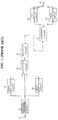
- a voice signal transmission system which encodes a voice parameter using the latter method is described below with reference to Fig. 1.
- input voice has two different frequency characteristics and a quantization circuit is designed for each of the characteristics respectively.
- the two frequency characteristics of input voice are frequency characteristic (hereinafter referred to as FLAT characteristic) in which the voice band is limited to a normal voice band and another frequency characteristic (hereinafter referred to as IRS characteristic) is emphasized in the high frequency region.
- FLAT characteristic frequency characteristic
- IRS characteristic another frequency characteristic
- Spectrum parameter extraction circuit 32 calculates a parameter representative of a spectrum envelope of input voice inputted through input terminal 31 for a frame after every fixed interval of time, and outputs the parameter as an input vector to first quantization circuit 33 and second quantization circuit 34.
- a known parameter called line spectrum pair LSP
- a method of analyzing a line spectrum pair is disclosed in Furui, "Digital voice Processing", the Publishing Society of Tokai University.
- First quantization circuit 33 is designed for the FLAT characteristic while second quantization circuit 34 is designed for the IRS characteristic.
- First quantization circuit 33 quantizes the input vector using the vector quantization described above and outputs the quantization vector to discrimination circuit 35. Further, first quantization circuit 33 outputs a code corresponding to the quantization vector to discrimination circuit 35.
- second quantization circuit 34 quantizes the input vector using the vector quantization described above and outputs the quantization vector to discrimination circuit 35. Further, second quantization circuit 34 outputs a code corresponding to the quantization vector to discrimination circuit 35.
- Discrimination circuit 35 discriminates characteristic of an input vector, either the FLAT characteristic or the IRS characteristic, based on the quantization vectors of first quantization circuit 33, second quantization circuit 34 and the input vector. Then, discrimination circuit 35 outputs a code of the input voice corresponding to the frequency characteristic and discrimination information representative of a result of the discrimination through transmission circuit 36.
- reception circuit 37 receives the code and the discrimination information transmitted thereto from transmission circuit 36 and is selectively connected to first dequantization circuit 38 or second dequantization circuit 39 in response to the discrimination information so that the selectively connected dequantization circuit may perform dequantization of the code to produce a dequantization vector corresponding to the code.
- the dequantization code is outputted from output terminal 40.
- a voice parameter encoding apparatus comprising a spectral parameter extraction circuit for calculating a voice parameter representative of a spectrum envelope of a voice input signal for each frame of every predetermined fixed interval of time, a first quantization circuit for quantizing the voice parameter outputted from the spectrum parameter extraction circuit as a parameter having a first frequency characteristic and outputting a first quantization vector and for outputting a first code representative of the first quantization vector, a second quantization circuit for quantizing the voice parameter outputted from the spectrum parameter extraction circuit as a parameter having a second frequency characteristic and outputting a second quantization vector and for outputting a second code representative of the second quantization vector, a discrimination circuit for receiving the first and second quantization vectors and the voice parameter outputted from the spectrum parameter extraction circuit, discriminating and selecting the one of either the first or second quantization vectors which is nearer to the audio parameter outputted from the spectrum parameter extraction circuit, calculating a difference between the selected first or second quantization
- the discrimination circuit refers, upon selection of the one of either the first or second quantization vectors which is nearer to the audio parameter outputted from the spectrum parameter extraction circuit, a weight as a result of discrimination performed in the past.
- a voice parameter decoding apparatus for decoding a transmission signal from a voice parameter encoding apparatus which includes a spectral parameter extraction circuit for calculating a voice parameter representative of a spectrum envelope of a voice input signal for each frame of every predetermined fixed interval of time, a first quantization circuit for quantizing the voice parameter outputted from the spectrum parameter extraction circuit as a parameter having a first frequency characteristic and outputting a first quantization vector and for outputting a first code representative of the first quantization vector, a second quantization circuit for quantizing the voice parameter outputted from the spectrum parameter extraction circuit as a parameter having a second frequency characteristic and outputting a second quantization vector and for outputting a second code representative of the second quantization vector, a discrimination circuit for receiving the first and second quantization vectors and the audio parameter outputted from the spectrum parameter extraction circuit, discriminating and selecting the one of either the first or second quantization vectors which is nearer to the voice parameter outputted from the spectrum parameter extraction circuit, calculating a difference between the selected
- a voice signal transmission system comprising the voice parameter encoding apparatus described above, the voice parameter decoding apparatus described above, and a transmission line for interconnecting between the transmission circuit of the audio parameter encoding apparatus and the reception circuit of the voice parameter decoding apparatus.
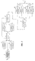
- Fig. 2 is a block diagram showing a system construction of a first embodiment of the voice signal transmission system of the present invention.
- input voice has two different frequency characteristics.
- the two frequency characteristics of the input voice are a frequency characteristic (hereinafter referred to as FLAT characteristic) in which the voice band is limited normaly and another frequency characteristic (hereinafter referred to as IRS characteristic) in which the voice is emphasized in a high frequency region.
- FLAT characteristic frequency characteristic
- IRS characteristic another frequency characteristic
- Spectrum parameter extraction circuit 2 calculates a parameter representative of a spectrum envelope of input voice inputted though input terminal 1 for a frame after every fixed number of frames, and outputs the calculated parameter as an input vector to first quantization circuit 3, second quantization circuit 4 and discrimination circuit 5.
- a known parameter called line spectrum pair is used as the parameter representative of a spectrum envelope.
- the parameter representative of a spectrum envelope is not limited to the line spectrum pair.
- First quantization circuit 3 is designed for the FLAT characteristic described above. First quantization circuit 3 quantizes the input vector from spectrum parameter extraction circuit 2 and outputs a quantization vector obtained as a result of the vector quantization to discrimination circuit 5. Further, first quantization circuit 3 outputs a code corresponding to the quantization vector to discrimination circuit 5.
- Second quantization circuit 4 is designed for the IRS characteristic described above. Second quantization circuit 4 quantizes the input vector from spectrum parameter extraction circuit 2 and outputs the quantization vector obtained as a result of the vector quantization to discrimination circuit 5. Further, second quantization circuit 4 outputs a code corresponding to the quantization vector to discrimination circuit 5.
- Discrimination circuit 5 discriminates to which frequency characteristic of the FLAT characteristic or the IRS characteristic an input voice belongs, based on the quantization vector of first quantization circuit 3, the quantization vector of second quantization circuit 4 and the input vector. Then, discrimination circuit 5 subtracts the quantization vector of the discriminated characteristic from the input vector to calculate an error vector.
- discrimination circuit 5 outputs the thus calculated error vector to third quantization circuit 6 and outputs the code corresponding to the quantization vector which was based on the calculation of the error vector and discrimination information representative of the discrimination result to transmission circuit 8.
- discrimination circuit 5 outputs the calculated error vector to fourth quantization circuit 7 and outputs the code corresponding to the quantization vector which was based on the calculation of the error vector and discrimination information representative of the discrimination result to transmission circuit 8.
- Third quantization circuit 6 is designed for the FLAT characteristic so that it may quantize the error vector of first quantization circuit 3. Third quantization circuit 6 quantizes the inputted error vector based on the discrimination result outputted from discrimination circuit 5, and outputs a code corresponding to the quantized error vector to transmission circuit 8.
- Fourth quantization circuit 7 is designed for the IRS characteristic in order to quantize the error vector of second quantization circuit 4. Fourth quantization circuit 7 quantizes the inputted error vector based on the discrimination result outputted from discrimination circuit 5 and outputs a code corresponding to the quantized error vector to transmission circuit 8.
- Transmission circuit 8 transmits the code and the discrimination information representative of the discrimination result inputted from discrimination circuit 5 as well as a code obtained from third quantization circuit 6 or fourth quantization circuit 7 to a decoding apparatus.
- Reception circuit 9 in the decoding apparatus receives the code and the discrimination information transmitted from transmission circuit 8.
- reception circuit 9 outputs the received code to first dequantization circuit 10 and third dequantization circuit 11.
- reception circuit 9 outputs the received code to second dequantization circuit 12 and fourth dequantization circuit 13.
- First dequantization circuit 10 performs dequantization corresponding to the quantization of first quantization circuit 3, and third dequantization circuit 11 performs dequantization corresponding to the quantization of third quantization circuit 6. Meanwhile, second dequantization circuit 12 performs dequantization corresponding to the quantization of second quantization circuit 4, and fourth dequantization circuit 13 performs dequantization corresponding to the quantization of fourth quantization circuit 7.
- First addition circuit 14 adds the quantization vector from first dequantization circuit 10 and the quantization vector from third dequantization circuit 11 and outputs a result of the addition to output terminal 16.
- Second addition circuit 15 adds the quantization vector from second dequantization circuit 12 and the quantization vector from fourth dequantization circuit 13 and outputs a result of the addition to output terminal 16.
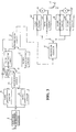
- the second embodiment of the present invention is described below with reference to Fig. 3.
- the frequency characteristic of input voice does not vary with unit of frame for which processing is performed, but relies upon the entire input voice to the audio parameter encoding apparatus. Therefore, when the discrimination circuit discriminates to which one of either the FLAT characteristic or the IRS characteristic an inputted voice belongs, the deterioration of the performance of the voice parameter encoder caused by an error in discrimination can be further reduced by discriminating the present frames on the basis of weighting the results of their past discrimination respectively.
- operation of discrimination circuit 5 using a result or results of discrimination in the past is described herein after. Operations of the other components are the same as those of the first embodiment shown in Fig. 2.
- Discrimination circuit 25 discriminates to which one of either the FLAT characteristic or the IRS characteristic an inputted voice belongs, based on a result or results of past discrimination obtained from delay circuit 25a, a quantization vector of first quantization circuit 3, another quantization vector of second quantization circuit 4 and an input vector. Then, discrimination circuit 25 subtracts the quantization vector of the discriminated characteristic from the input vector to obtain an error vector and outputs the error vector to third quantization circuit 6 or fourth quantization circuit 7 in response to the result of discrimination. Further, discrimination circuit 25 outputs a corresponding code and discrimination information representative of the result of discrimination to transmission circuit 8.
- the following method may be used.
- For the evaluated value a square of distance between the quantization vectors obtained from the first and second quantization circuits and the input vector is used.
- the present invention since it is discriminated to which frequency characteristics an input vector belongs and limits the operation of quantization circuit only for the quantization circuits which are provided for the discriminated frequency characteristic, the amount of calculation can be reduced, and deterioration in performance can be prevented.
Landscapes
- Engineering & Computer Science (AREA)
- Physics & Mathematics (AREA)
- Spectroscopy & Molecular Physics (AREA)
- Computational Linguistics (AREA)
- Signal Processing (AREA)
- Health & Medical Sciences (AREA)
- Audiology, Speech & Language Pathology (AREA)
- Human Computer Interaction (AREA)
- Acoustics & Sound (AREA)
- Multimedia (AREA)
- Compression, Expansion, Code Conversion, And Decoders (AREA)
- Transmission Systems Not Characterized By The Medium Used For Transmission (AREA)
Applications Claiming Priority (3)
| Application Number | Priority Date | Filing Date | Title |
|---|---|---|---|
| JP7005090A JP2982637B2 (ja) | 1995-01-17 | 1995-01-17 | スペクトルパラメータを用いた音声信号伝送システムおよびそれに用いられる音声パラメータ符号化装置および復号化装置 |
| JP509095 | 1995-01-17 | ||
| JP5090/95 | 1995-01-17 |
Publications (3)
| Publication Number | Publication Date |
|---|---|
| EP0723257A2 true EP0723257A2 (de) | 1996-07-24 |
| EP0723257A3 EP0723257A3 (de) | 1998-01-07 |
| EP0723257B1 EP0723257B1 (de) | 2002-04-24 |
Family
ID=11601703
Family Applications (1)
| Application Number | Title | Priority Date | Filing Date |
|---|---|---|---|
| EP96100660A Expired - Lifetime EP0723257B1 (de) | 1995-01-17 | 1996-01-17 | System zur Signalübertragung mittels spektraler Parameter und Vorrichtung zur Kodierung und Dekodierung von Sprachparametern dafür |
Country Status (5)
| Country | Link |
|---|---|
| US (1) | US5734679A (de) |
| EP (1) | EP0723257B1 (de) |
| JP (1) | JP2982637B2 (de) |
| CA (1) | CA2167327C (de) |
| DE (1) | DE69620808T2 (de) |
Cited By (2)
| Publication number | Priority date | Publication date | Assignee | Title |
|---|---|---|---|---|
| WO1998023039A1 (en) * | 1996-11-18 | 1998-05-28 | Innomedia Pte Ltd | Concatenation compression method |
| EP0968497A4 (de) * | 1996-10-07 | 2000-02-23 | Picturetel Corp | Audio-kopierverfahren mit veränderlicher kodelänge unter verwendung einer mehrzahl von teilband-bitverteilungsmoden |
Families Citing this family (2)
| Publication number | Priority date | Publication date | Assignee | Title |
|---|---|---|---|---|
| US6947886B2 (en) * | 2002-02-21 | 2005-09-20 | The Regents Of The University Of California | Scalable compression of audio and other signals |
| ATE348386T1 (de) * | 2002-11-28 | 2007-01-15 | Koninkl Philips Electronics Nv | Audiosignalkodierung |
Family Cites Families (7)
| Publication number | Priority date | Publication date | Assignee | Title |
|---|---|---|---|---|
| JPS6032100A (ja) * | 1983-08-03 | 1985-02-19 | 日本電気株式会社 | Lsp型パタンマッチングボコ−ダ |
| JP2605256B2 (ja) * | 1985-03-20 | 1997-04-30 | 日本電気株式会社 | Lspパタンマツチングボコーダ |
| JP3114197B2 (ja) * | 1990-11-02 | 2000-12-04 | 日本電気株式会社 | 音声パラメータ符号化方法 |
| US5271089A (en) * | 1990-11-02 | 1993-12-14 | Nec Corporation | Speech parameter encoding method capable of transmitting a spectrum parameter at a reduced number of bits |
| JP3151874B2 (ja) * | 1991-02-26 | 2001-04-03 | 日本電気株式会社 | 音声パラメータ符号化方式および装置 |
| JP2936757B2 (ja) * | 1991-03-08 | 1999-08-23 | 三菱電機株式会社 | 量子化器 |
| JP3088163B2 (ja) * | 1991-12-18 | 2000-09-18 | 沖電気工業株式会社 | Lsp係数の量子化方法 |
-
1995
- 1995-01-17 JP JP7005090A patent/JP2982637B2/ja not_active Expired - Fee Related
-
1996
- 1996-01-16 CA CA002167327A patent/CA2167327C/en not_active Expired - Fee Related
- 1996-01-16 US US08/584,950 patent/US5734679A/en not_active Expired - Lifetime
- 1996-01-17 EP EP96100660A patent/EP0723257B1/de not_active Expired - Lifetime
- 1996-01-17 DE DE69620808T patent/DE69620808T2/de not_active Expired - Fee Related
Cited By (3)
| Publication number | Priority date | Publication date | Assignee | Title |
|---|---|---|---|---|
| EP0968497A4 (de) * | 1996-10-07 | 2000-02-23 | Picturetel Corp | Audio-kopierverfahren mit veränderlicher kodelänge unter verwendung einer mehrzahl von teilband-bitverteilungsmoden |
| WO1998023039A1 (en) * | 1996-11-18 | 1998-05-28 | Innomedia Pte Ltd | Concatenation compression method |
| US6178405B1 (en) | 1996-11-18 | 2001-01-23 | Innomedia Pte Ltd. | Concatenation compression method |
Also Published As
| Publication number | Publication date |
|---|---|
| DE69620808D1 (de) | 2002-05-29 |
| EP0723257B1 (de) | 2002-04-24 |
| CA2167327A1 (en) | 1996-07-18 |
| EP0723257A3 (de) | 1998-01-07 |
| DE69620808T2 (de) | 2002-09-26 |
| JP2982637B2 (ja) | 1999-11-29 |
| JPH08195722A (ja) | 1996-07-30 |
| CA2167327C (en) | 1999-10-12 |
| US5734679A (en) | 1998-03-31 |
Similar Documents
| Publication | Publication Date | Title |
|---|---|---|
| US5125030A (en) | Speech signal coding/decoding system based on the type of speech signal | |
| EP0802524B1 (de) | Sprachkodierer | |
| EP0736858B1 (de) | Mobile Kommunikationseinrichtung | |
| JPH0519331B2 (de) | ||
| EP1162603B1 (de) | Sprachkodierer hoher Qualität mit niedriger Bitrate | |
| EP1241664B1 (de) | Vorrichtung zur Sprachcodierung und Sprachdecodierung mit Paketfehlerresistenz sowie Verfahren dafür | |
| US5113448A (en) | Speech coding/decoding system with reduced quantization noise | |
| EP0708435B1 (de) | Gerät zur Kodierung und Dekodierung von Linienspektrumpaarparametern | |
| US4571737A (en) | Adaptive differential pulse code modulation decoding circuit | |
| JP3248215B2 (ja) | 音声符号化装置 | |
| US5734679A (en) | Voice signal transmission system using spectral parameter and voice parameter encoding apparatus and decoding apparatus used for the voice signal transmission system | |
| EP0971337A1 (de) | Verfahren und vorrichtung zur hervorhebung der sprachgrundfrequenz | |
| EP0186196B1 (de) | Verfahren und Vorrichtung zur Kodierung/Dekodierung eines Bildsignals | |
| JP3067676B2 (ja) | Lspの予測符号化装置及び方法 | |
| EP0694907A2 (de) | Sprachkodierer | |
| EP1688918A1 (de) | Sprachdekodierung | |
| JP3496618B2 (ja) | 複数レートで動作する無音声符号化を含む音声符号化・復号装置及び方法 | |
| JP2870608B2 (ja) | 音声ピッチ予測装置 | |
| JP3010648B2 (ja) | 信号符号化装置及び信号符号化方法 | |
| JPH03263100A (ja) | 音声符号化・復号化装置 | |
| JP2952878B2 (ja) | デイジタル信号処理装置 | |
| JP2605679B2 (ja) | パタン符号化復号化方式及び装置 | |
| JP2537243B2 (ja) | 動き補償動ベクトルの符号化方式 | |
| EP1269462B1 (de) | Verfahren und vorrichtung zur sprachaktivitätsdetektion | |
| JPH0563579A (ja) | 音声検出器 |
Legal Events
| Date | Code | Title | Description |
|---|---|---|---|
| PUAI | Public reference made under article 153(3) epc to a published international application that has entered the european phase |
Free format text: ORIGINAL CODE: 0009012 |
|
| AK | Designated contracting states |
Kind code of ref document: A2 Designated state(s): DE FR GB IT SE |
|
| PUAL | Search report despatched |
Free format text: ORIGINAL CODE: 0009013 |
|
| AK | Designated contracting states |
Kind code of ref document: A3 Designated state(s): DE FR GB IT SE |
|
| 17P | Request for examination filed |
Effective date: 19971202 |
|
| 17Q | First examination report despatched |
Effective date: 20000315 |
|
| GRAG | Despatch of communication of intention to grant |
Free format text: ORIGINAL CODE: EPIDOS AGRA |
|
| RIC1 | Information provided on ipc code assigned before grant |
Free format text: 7G 10L 19/02 A |
|
| GRAG | Despatch of communication of intention to grant |
Free format text: ORIGINAL CODE: EPIDOS AGRA |
|
| GRAG | Despatch of communication of intention to grant |
Free format text: ORIGINAL CODE: EPIDOS AGRA |
|
| GRAH | Despatch of communication of intention to grant a patent |
Free format text: ORIGINAL CODE: EPIDOS IGRA |
|
| REG | Reference to a national code |
Ref country code: GB Ref legal event code: IF02 |
|
| GRAH | Despatch of communication of intention to grant a patent |
Free format text: ORIGINAL CODE: EPIDOS IGRA |
|
| GRAA | (expected) grant |
Free format text: ORIGINAL CODE: 0009210 |
|
| AK | Designated contracting states |
Kind code of ref document: B1 Designated state(s): DE FR GB IT SE |
|
| REG | Reference to a national code |
Ref country code: GB Ref legal event code: FG4D |
|
| REF | Corresponds to: |
Ref document number: 69620808 Country of ref document: DE Date of ref document: 20020529 |
|
| ET | Fr: translation filed | ||
| PLBE | No opposition filed within time limit |
Free format text: ORIGINAL CODE: 0009261 |
|
| STAA | Information on the status of an ep patent application or granted ep patent |
Free format text: STATUS: NO OPPOSITION FILED WITHIN TIME LIMIT |
|
| 26N | No opposition filed |
Effective date: 20030127 |
|
| PGFP | Annual fee paid to national office [announced via postgrant information from national office to epo] |
Ref country code: DE Payment date: 20090115 Year of fee payment: 14 |
|
| PGFP | Annual fee paid to national office [announced via postgrant information from national office to epo] |
Ref country code: GB Payment date: 20090114 Year of fee payment: 14 |
|
| PGFP | Annual fee paid to national office [announced via postgrant information from national office to epo] |
Ref country code: IT Payment date: 20090127 Year of fee payment: 14 |
|
| PGFP | Annual fee paid to national office [announced via postgrant information from national office to epo] |
Ref country code: FR Payment date: 20090113 Year of fee payment: 14 |
|
| PGFP | Annual fee paid to national office [announced via postgrant information from national office to epo] |
Ref country code: SE Payment date: 20091218 Year of fee payment: 15 |
|
| GBPC | Gb: european patent ceased through non-payment of renewal fee |
Effective date: 20100117 |
|
| REG | Reference to a national code |
Ref country code: FR Ref legal event code: ST Effective date: 20100930 |
|
| PG25 | Lapsed in a contracting state [announced via postgrant information from national office to epo] |
Ref country code: FR Free format text: LAPSE BECAUSE OF NON-PAYMENT OF DUE FEES Effective date: 20100201 |
|
| PG25 | Lapsed in a contracting state [announced via postgrant information from national office to epo] |
Ref country code: DE Free format text: LAPSE BECAUSE OF NON-PAYMENT OF DUE FEES Effective date: 20100803 |
|
| PG25 | Lapsed in a contracting state [announced via postgrant information from national office to epo] |
Ref country code: GB Free format text: LAPSE BECAUSE OF NON-PAYMENT OF DUE FEES Effective date: 20100117 |
|
| PG25 | Lapsed in a contracting state [announced via postgrant information from national office to epo] |
Ref country code: IT Free format text: LAPSE BECAUSE OF NON-PAYMENT OF DUE FEES Effective date: 20100117 |
|
| REG | Reference to a national code |
Ref country code: SE Ref legal event code: EUG |
|
| PG25 | Lapsed in a contracting state [announced via postgrant information from national office to epo] |
Ref country code: SE Free format text: LAPSE BECAUSE OF NON-PAYMENT OF DUE FEES Effective date: 20110118 |