EP0723313B1 - Elektrischer Verbinder - Google Patents
Elektrischer Verbinder Download PDFInfo
- Publication number
- EP0723313B1 EP0723313B1 EP96100147A EP96100147A EP0723313B1 EP 0723313 B1 EP0723313 B1 EP 0723313B1 EP 96100147 A EP96100147 A EP 96100147A EP 96100147 A EP96100147 A EP 96100147A EP 0723313 B1 EP0723313 B1 EP 0723313B1
- Authority
- EP
- European Patent Office
- Prior art keywords
- longitudinal axis
- electrical connector
- terminal
- housing
- contact
- Prior art date
- Legal status (The legal status is an assumption and is not a legal conclusion. Google has not performed a legal analysis and makes no representation as to the accuracy of the status listed.)
- Expired - Lifetime
Links
- 230000013011 mating Effects 0.000 claims description 25
- 238000003780 insertion Methods 0.000 claims description 21
- 230000037431 insertion Effects 0.000 claims description 21
- 230000014759 maintenance of location Effects 0.000 claims description 13
- 230000000717 retained effect Effects 0.000 claims description 8
- 238000007789 sealing Methods 0.000 claims description 7
- 230000000295 complement effect Effects 0.000 description 5
- 238000006073 displacement reaction Methods 0.000 description 4
- 239000004020 conductor Substances 0.000 description 2
- 230000003993 interaction Effects 0.000 description 2
- 230000000694 effects Effects 0.000 description 1
- 238000004519 manufacturing process Methods 0.000 description 1
- 239000000463 material Substances 0.000 description 1
- 230000004048 modification Effects 0.000 description 1
- 238000012986 modification Methods 0.000 description 1
- 230000002093 peripheral effect Effects 0.000 description 1
- 230000007704 transition Effects 0.000 description 1
Images





Classifications
-
- H—ELECTRICITY
- H01—ELECTRIC ELEMENTS
- H01R—ELECTRICALLY-CONDUCTIVE CONNECTIONS; STRUCTURAL ASSOCIATIONS OF A PLURALITY OF MUTUALLY-INSULATED ELECTRICAL CONNECTING ELEMENTS; COUPLING DEVICES; CURRENT COLLECTORS
- H01R13/00—Details of coupling devices of the kinds covered by groups H01R12/70 or H01R24/00 - H01R33/00
- H01R13/62—Means for facilitating engagement or disengagement of coupling parts or for holding them in engagement
- H01R13/629—Additional means for facilitating engagement or disengagement of coupling parts, e.g. aligning or guiding means, levers, gas pressure electrical locking indicators, manufacturing tolerances
- H01R13/62905—Additional means for facilitating engagement or disengagement of coupling parts, e.g. aligning or guiding means, levers, gas pressure electrical locking indicators, manufacturing tolerances comprising a camming member
-
- H—ELECTRICITY
- H01—ELECTRIC ELEMENTS
- H01R—ELECTRICALLY-CONDUCTIVE CONNECTIONS; STRUCTURAL ASSOCIATIONS OF A PLURALITY OF MUTUALLY-INSULATED ELECTRICAL CONNECTING ELEMENTS; COUPLING DEVICES; CURRENT COLLECTORS
- H01R13/00—Details of coupling devices of the kinds covered by groups H01R12/70 or H01R24/00 - H01R33/00
- H01R13/40—Securing contact members in or to a base or case; Insulating of contact members
- H01R13/42—Securing in a demountable manner
- H01R13/436—Securing a plurality of contact members by one locking piece or operation
- H01R13/4361—Insertion of locking piece perpendicular to direction of contact insertion
- H01R13/4362—Insertion of locking piece perpendicular to direction of contact insertion comprising a temporary and a final locking position
-
- H—ELECTRICITY
- H01—ELECTRIC ELEMENTS
- H01R—ELECTRICALLY-CONDUCTIVE CONNECTIONS; STRUCTURAL ASSOCIATIONS OF A PLURALITY OF MUTUALLY-INSULATED ELECTRICAL CONNECTING ELEMENTS; COUPLING DEVICES; CURRENT COLLECTORS
- H01R13/00—Details of coupling devices of the kinds covered by groups H01R12/70 or H01R24/00 - H01R33/00
- H01R13/40—Securing contact members in or to a base or case; Insulating of contact members
- H01R13/42—Securing in a demountable manner
Definitions
- This invention relates to an electrical connector and in particular to an electrical connector housing wherein terminals are disposed having a positive retention structure to assure the contacts are retained therein.
- Modern electrical connector housings and particularly those used in automotive applications, include a number of desirable features. These electrical connectors can prevent the ingress of contaminates by incorporating sealing members so that the electrical interconnection does not deteriorate. It is also known to incorporate shoulders into a terminal receiving cavity such that locking lances extending outward from the terminal interfere with these shoulders to assure that the terminal is properly positioned and retained within the cavity. Furthermore, in order to assure that the terminals remain in their proper position, secondary locking members which are displaceable between an open position wherein the terminal may be seated in the passageway and a locked position where the secondary locking member now obstructs the passageway such that it would interfere with the inserted terminal to prevent removal from the passageway.
- EP 317 755 A1 discloses an electrical connector with all features of the pre-characterizing portion of claim 1.
- the terminal longitudinal axis is always parallel to the second longitudinal axis of the second part and is moved relative to the first longitudinal axis of the first part.
- the connector described in this document is not sealed.
- a very similar design is also discussed in EP 522 427 A1.
- a sealed connector design is known from DE 41 23 505 C1.
- each terminal is combined with a single wire seal. These seal the terminals in the terminal receiving passageways. The terminals have only one position relative to the first housing part.
- the connector comprises at least one terminal and a housing having a terminal receiving passageway extending therethrough, where the passageway includes an insertion portion having a longitudinal axis and a contact retaining portion having a longitudinal axis.
- the housing includes a first part having the insertion portion therein and a second part having the contact retaining portion therein, where the second part is displaceable between a first position where the longitudinal axes are offset from each other to a second position where the longitudinal axis of the insertion portion and the contact retaining portion coincide.
- the terminals are insertable in the first position and retained in the second position.
- the terminal longitudinal axis is skewed relative the longitudinal axis of the insertion portion when the second part is in the first position.
- the terminals may be inserted into the passageway while a complementary connector is prevented from mating therewith. It is still another advantage of this invention that in the second position a locking shoulder formed on the first part blocks the terminal from being withdrawn from the passageway. It is still yet another advantage of this invention that seals may be disposed upon the connector and retained thereupon by the second part.
- While a connector of the type described above has a number of advantages there is a problem presented in that during assembly of the contact retaining portion to the housing it is desired that the contact retaining portion be received thereupon in the first position so that the terminals may be easily received in their respective passageways. It is important to note that as the contact retaining portion is typically latched to the housing, it is not done so in a way that makes movement between the first and second positions equally easy independent of which way the housing/contact retaining portions are moved. For example, as it is undesirable for the secondary locking or positive contact retention features to be easily released the latching structure is typically constructed in a way that makes movement between the first to the second position relatively easy to accomplish, but movement between the second to the first position difficult or impossible without damage to the connector or use of special tools. This means that, as the contact retaining portion is being attached to the housing, it would be desirable to assure it will only be affixed thereto in the first position. This would then eliminate any loss of time or materials due to improper assembly.
- an electrical connector comprises a housing and a contact retaining portion where the housing includes passageways extending therethrough for receiving terminals and the contact retaining portion is configured to positively retain the terminals within the passageway as a result of displacement from a first position where the terminals are receivable and a second position where the terminals are blocked from being withdrawn; the connector being characterized in that the contact retaining portion and the housing include complementary camming features that cooperate to assure the contact retaining portion can only be received on the housing in the first position.
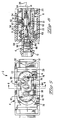
- the electrical connector 2 includes a first part 4 and a second part 6 where a terminal receiving passageway 8 extends therethrough.
- the first part 4 includes a body portion 10 wherein an insertion portion 12 of the terminal receiving passageway 8 extends longitudinally therethrough.
- the insertion portion 12 defines a first longitudinal axis 14.
- Integrally formed with the body portion 10 is an outer shroud 16 that extends forwardly to a mating end 18.
- the shroud 16 is disposed outward from the body 10 to define an annular receiving cavity 20 that is open at the front mating end 18 for closely receiving a shroud of a mating component (not shown).
- a seal member 22 Disposed within this annular cavity 20 about a portion of the body 10 is a seal member 22 which interacts with the internal surfaces of the shroud of the mating component to form a contaminant-tight seal.
- the second part 6 is also encompassed by the shroud 16 and includes a contact retaining portion 24 of the terminal receiving passageway 8.
- the contact retaining portion 24 defines a second longitudinal axis 26 that extends therethrough.
- the first part 4 is shown in this embodiment as being generally rectangular in shape having latching members 28 at either end thereof for cooperating with the mating connector component (not shown) to effect positive retention of the contacts ( Figure 6 and Figure 8).
- the first part 4 includes a single row of three insertion portions 12 of the terminal receiving passageway 8. It should be appreciated that, while only a single row is shown, additional configurations having a greater or lesser number of rows with more-or-less insertion portions 12 incorporated therein would be obvious in light of the present invention.
- the present invention is illustrated with a generally rectangular connector, it would be applicable to other configurations as well, such as circular.
- the seal 22 is carried upon an inner sealing surface 30 and exposed to the annular cavity 20. Spanning the array of insertion portions 12 are a pair of sides 32,34 that are integrally connected with a base member 36 to form a wide U-shaped seating channel 38 therebetween.
- side 32 is similarly configured to side 34, both of which include a port 40 therethrough for receiving a boss (not shown) on the second connector part 6 for longitudinally retaining the second connector part 6 with the first connector part 4.
- a triangular latching barb 42' that works in conjunction with first and second latching shoulders 44,46 respectively, at the mating free end 48 of the side 32, to assure that the second part 6 is stabily maintained in both the first and second positions, as will be described below.
- the walls 32,34 and the base 36 extend outward from a mating face 54.
- the insertion portion 12 is open at the mating face through a rectangular opening 56, the rectangular opening 56 transitions thereto from a cylindrical seal seat 58 at least partially through a ramp 60 so that the opening 56 is offset from the longitudinal axis 14 thereby providing a stop shoulder 61 along face 54 for retaining a contact therein.
- the second part 6 includes the contact retaining portion 24 extending along axis 26.
- the contact retaining portion 24 includes a guide section 62 wherein multiple ribs 64 form a cross-shaped opening 66 (best seen in Figure 5 and Figure 7) for receiving a blade contact of mating connector component (not shown).
- the second part includes contact retaining portions 24 corresponding in number and arrangement to the insertion portions 12 of the first part 4 of the connector housing 2. Opposite the cross-like openings 66, the contact retaining portions 24 are open at 67 along a rear face 68.
- the second part 6 Extending rearward from the rear face 68 are a pair of seal-captivating members 70,72 that seat within corresponding notches 50,52 to assure that the seal 22 remains captivated upon body portion 10 of the first part 4.
- the second part 6 also includes coding openings 74 on opposite sides of the contact retaining portions 24 to assure that the proper mating is achieved. Note, it is advantageous that the only modification needed for differently coded connectors is to the moulds used to produce the second part 6. It may also be possible to manipulate the second part 6 between the first position and a second position by way of these coding openings 74.
- the electrical connector housing 2 is shown with the second part 6 mounted upon the first part 4 in a first preloaded position.
- the first preloaded position is established and stabily maintained by interaction of catches (not shown) with the latches 42 and the boss (not shown) with the port 40 as previously described with reference to Figure 3.
- the second part 6 includes a pair of slits 76 that partially separate outer extremities 78 from the remainder of the second part 6 so that the second part 6 may be displaced into the second position, as described below, by providing resiliency to the portion of the second part 6 which carries the catches (not shown) which interact with the latches 42 as previously described.
- the second part 6 further includes an outer peripheral edge 80 extending therearound which can be seen to be offset from the seal member 22 such that the region 82 above the second member 6 is less than the region 84 below the second part 6. This can also be observed by comparing transverse lines 26' and 14' which interconnect the longitudinal axes 14,26 of the portions of the passageway 8 in second part 6 and the first part 4 respectively. In this first position, as better seen in Figure 6, the longitudinal axes 14,26 of the respective first and second parts 4,6 are offset from each other. However, the opening 56 in the first part corresponds to the opening 67 in the second part such that a continuous passageway is formed therethrough, whereby a contact 86 may be inserted and retained.
- the electrical connector contact 86 is terminated to an electrical conductor 88 and a single wire sealing member 90 is disposed thereupon.
- the contact rides up and over ramp 60 and into the contact retaining portion 24 such that locking lances 91 are behind shoulders 92 in the contact retaining portion 24.
- the contact 86 and its associated conductor 88 define another longitudinal axis 94, which due to the misalignment of the longitudinal axes 14,26 of the first and second parts 4,6 is angularly skewed relative thereto.
- the rectangular opening 56 as described with reference to Figure 2 and Figure 3, properly orients and accepts the contact 86 within the second part 6.
- the second part 6 is shifted down in the direction of arrow A so that the upper region 82 and the lower region 84 of the annular cavity 20 are now of corresponding size so that the shroud of a mating connector component (not shown) may be inserted therein.
- the second part 6 is correspondingly aligned with the seal 22 and lines 14',26' that interconnect the axes 14,26 coincide.
- the extreme portions 78 are able to deflect so that the catches (not shown) pass over ramp surface ( Figure 3) located above latch surface 46 and correspondingly, the catches associated with the latches 42 also are displaced.
- the longitudinal axes 14,26,94 defined by the insertion portion 12, the contact retention portion 24 and the contact 86 coincide. Furthermore, in this second position the opening 56 and the opening 67 are no longer aligned and the effective opening therethrough is reduced to less than the contact body 96 such that the shoulder 60 along face 54 of the first part 4, realized by the ramp 60, acts as a locking shoulder to prevent the contact 86 from being withdrawn from the contact receiving passageway 8.
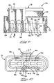
- the connector 100 includes a housing 102 and a contact retaining member 104 that positively retains terminals (not shown) within passageways 106 that extend between a mating end 108 and a wire receiving end 110.
- each passageway 106 includes an insertion portion 112 and a contact retaining portion 114 in the housing 102 and the contact retaining member 104, respectively, that function similarly.
- the housing 102 includes multiple wings 116a-c that function to position and retain the contact retaining member 104 as is described below. In the embodiment, the wings 116a-c are arranged in corresponding opposed pairs, as best seen in Figures 10 and 11.
- the wings 116a-c pairs are disposed within a forwardly extending shroud 118 that surrounds the area wherein the mating connector (not shown) is received.
- a latching structure 120 is provided for holding the mated connectors together.
- the contact retaining member 104 has a front face 122 with a plurality of mating contact receiving openings 124 through which the mating connector tabs (not shown) enter into the connector and engage the contacts therein.
- the contact retaining member 104 is generally symmetrical about a longitudinal axis 126 defined thereby.
- a plurality of seal supports 128 extend rearward and are configured to cooperate with a seal (not shown) to retain the seal in position.
- a wing retaining region 130a-c is then formed between each seal support 128 that corresponds to the wings 116a-c.
- a camming post 138 extends outward from at least one of the walls 136.
- the camming post 138 includes a camming surface 140 facing in the direction of insertion of the contact retaining member 104 upon the housing 102 for cooperation therewith.
- the camming post 138 further includes a positioning surface 142 that in cooperation with the housing 102, as described below, assures that the contact retaining member 104 is positioned in the first position wherein contacts may be inserted into the connector.
- a retention surface 144 is disposed on the opposite side of the camming post 138 from the camming surface 140 in order to prevent the contact retaining member 104 from becoming disengaged from the housing 102 when in the second position. Further included along the base surface 132 are positioning posts 146 that ensure the contact retaining member 104 stays properly positioned upon the housing 102. Within the center wing receiving region 130b latches 148 extend outward and include a camming surface facing the direction of movement from the first position to the second position, thereby enabling displacement thereto, and a locking surface facing opposite the camming surface such that when the contact retaining member 104 has been displaced to the second position, it is difficult to move the contact retaining member 104 back to the first position.
- the housing 102 includes receiving notches 150 located along at least one of the wings 116a-c that correspond to the camming post 138 of the contact receiving member 104.
- the wings also include ports 152 that are sized to receive the posts 146 therein and prevent the contact retaining member 104 from being removed from the housing 102.
- one of the wings 116b includes a latch receiving feature 154 having first and second regions 156,158 respectively for receiving the latch 148 therein in corresponding first and second positions of the contact retaining member 104.
- the contact retaining member 104 is set upon the connector with the wing portions 116a-c corresponding to the wing receiving regions 130a-c. It is possible to have this initial assembly with either the contact retaining member 104 in the first or second position. It is typically difficult to visually align the two at this time as the distance between the first and second positions is usually small and the contact retaining member 104 is to be seated within the outer shroud 118.
- the positioning latching structure 148,154 does not engage until the contact retaining member 104 is almost fully inserted in the direction of arrow B, even if it were to be constructed to be initially engaged as the contact retaining member 104 is mounted upon the housing 102, there would still be difficulties in assuring the proper alignment occurs and is maintained during insertion.
- the camming post 138 is constructed so that as the contact retaining member 104 is inserted in the direction of arrow B, the leading camming surface 140 comes into contact with the camming surface 160 that is located along one of the wings 116c.
- the contact ⁇ retaining member 104 is displaced to one side and into the first position as biasing surface 142 passes along the corresponding positioning surface 162.
- the camming post 138 is displaced opposite the notch 150 such that upon displacement of the contact retaining member 104 to the second position, the camming post 138 is received within the receiving notch 150.
- the ports 152 are oversized in relation to the posts 146 thereby enabling the transverse movement of the contact retaining member 104.
- the connector 2 may be shipped from manufacture to the assembly site with the seal 22 mounted upon the first part 4 and the second part 6 also engaged therewith in a position for receiving the electrical contact 86 within the terminal passageway 8.
- the electrical contact 86 may be inserted and seated by interaction of lances 91 with shoulders 92, but mating is prevented until the locking is positively effected by shifting the second part 6 to expose shoulder 60 behind the contact 86.
- camming features on both the housing and contact retaining member are configured to cooperate as the contact retaining member is seated upon the housing, it is possible to assure that the contact retaining member is reliably positioned such that the contacts may be positioned in the connector without requiring repositioning of the contact retaining member.
Landscapes
- Connector Housings Or Holding Contact Members (AREA)
Claims (9)
- Elektrischer Verbinder, der ein Gehäuse (2) und wenigstens eine Klemme (86) aufweist, die eine Klemmenlängsachse (94) definiert, wobei das Gehäuse (2) eine durch dieses hindurchführende Klemmendurchführung (8) hat, um darin eine der Klemmen (86) aufzunehmen, wobei das Gehäuse (2) außerdem einen ersten Teil (4), der einen Einführungsabschnitt der Durchführung (8) einschließt, der eine erste Längsachse (14) definiert, und einen zweiten Teil (6) hat, der einen Kontakthalteabschnitt (24) der Durchführung (8) einschließt, der eine zweite Längsachse (26) hat, wobei der zweite Teil (6) verschiebbar ist zwischen einer ersten Position, in der die Längsachsen (14, 26) der Teile gegeneinander versetzt sind, und einer zweiten Position, in der die erste und zweite Längsachse (14, 26) zusammenfallen, und wobei die Klemmen (86) in der ersten Position eingeführt werden können und in der zweiten Position gehalten werden, dadurch gekennzeichnet, daß die Klemmenlängsachse (94) im Verhältnis zu den Längsachsen (14, 26) des Einführungsabschnitts (12) und des Halteabschnitts (24) schräggestellt ist, wenn die Klemme (86) in das Gehäuse eingeführt wird, während sich der zweite Teil (6) in der ersten Position befindet, außerdem dadurch gekennzeichnet, daß die Klemme (86) für die Aufnahme eines Eindraht-Abdichtelements (90) konfiguriert ist und die klemmenaufnehmende Durchführung (8) des Gehäuses (2) für das abdichtende Zusammenwirken mit dem Eindraht-Abdichtelement (90) konfiguriert ist.
- Elektrischer Verbinder nach Anspruch 1, außerdem dadurch gekennzeichnet, daß der erste Teil (4) längs des Einführungsabschnitts (12) eine Rampe (60) einschließt, um eine Öffnung (56) bereitzustellen, die gegenüber der Längsachse (14) versetzt ist, so daß ein Halteabsatz (61) gebildet wird und der Halteabschnitt (61) exponiert ist, wenn der zweite Teil (6) in die zweite Position bewegt wird.
- Elektrischer Verbinder nach Anspruch 1 oder Anspruch 2, außerdem dadurch gekennzeichnet, daß der zweite Teil (6) längs des Halteabschnitts (24) einen Absatz (92) für das Zusammenwirken mit einer Verriegelungslanze (91) der darin eingeführten Klemme (86) einschließt.
- Elektrischer Verbinder nach einem der vorhergehenden Ansprüche, außerdem dadurch gekennzeichnet, daß der erste Teil (4) ein Abdichtelement (22) trägt, das durch eine Ummantelung (16) umschlossen wird, um einen ringförmigen Hohlraum (20) zu bilden, worin ein Abschnitt einer Gegenverbinderkomponente zur Bildung einer gekapselten Verbindung aufzunehmen ist, und bei dem der zweite Teil (6) Dichtungshalteelemente (70, 72) trägt, die gewährleisten, daß das Abdichtelement (22) korrekt positioniert bleibt.
- Elektrischer Verbinder nach einem der vorhergehenden Ansprüche, außerdem dadurch gekennzeichnet, daß der erste Teil nach vorn verlaufende Seiten (32, 34) einschließt, die durch eine Basis (36) untereinander verbunden sind, um eine U-förmige Auflage (38) zu bilden, in welcher der zweite Teil (6) positioniert ist.
- Elektrischer Verbinder nach Anspruch 5, außerdem dadurch gekennzeichnet, daß die Seiten (32, 34) Elemente (40) einschließen, die mit dem zweiten Teil (6) zusammenwirken, um die ersten und zweiten Positionen herzustellen.
- Elektrischer Verbinder nach einem der vorhergehenden Ansprüche, bei dem der zweite Teil (6) eine Öffnung (66) einschließt, um darin engsitzend eine Gegenkontaktklemme aufzunehmen, wobei die Öffnung (66) mit der Längsachse (26) des zweiten Teils (6) ausgerichtet ist, so daß in der ersten Position die Versetzung zwischen der Längsachse (94) des Kontakts (86) und der Längsachse (26) des zweiten Teils (6) ausreicht, um die Einführung der Gegenkontaktklemme in den Kontakt (86) zu verhindern.
- Elektrischer Verbinder nach einem der vorhergehenden Ansprüche, bei dem das Verbindergehäuse (2) eine Vielzahl von klemmenaufnehmenden Durchführungen (8) einschließt, die jeweils im ersten und im zweiten Teil (4, 6) angeordnet sind, um eine Reihe von Durchführungen (8) zu bilden, wobei der zweite Teil durch eine Bewegung quer zu der Reihe aus der ersten Position in die zweite Position verschoben werden kann.
- Elektrischer Verbinder nach einem der vorhergehenden Ansprüche, dadurch gekennzeichnet, daß der zweite Teil (104) und der erste Teil (102) Nockenelemente (138, 160) einschließen, die zusammenwirken, während der zweite Teil (104) in den ersten Teil (102) eingeführt wird, um zu gewährleisten, daß der zweite Teil (104) in dei ersten Position angebracht wird.
Applications Claiming Priority (2)
| Application Number | Priority Date | Filing Date | Title |
|---|---|---|---|
| GB9500877 | 1995-01-17 | ||
| GBGB9500877.7A GB9500877D0 (en) | 1995-01-17 | 1995-01-17 | Electrical connector |
Publications (3)
| Publication Number | Publication Date |
|---|---|
| EP0723313A2 EP0723313A2 (de) | 1996-07-24 |
| EP0723313A3 EP0723313A3 (de) | 1997-07-02 |
| EP0723313B1 true EP0723313B1 (de) | 2001-12-19 |
Family
ID=10768138
Family Applications (1)
| Application Number | Title | Priority Date | Filing Date |
|---|---|---|---|
| EP96100147A Expired - Lifetime EP0723313B1 (de) | 1995-01-17 | 1996-01-08 | Elektrischer Verbinder |
Country Status (7)
| Country | Link |
|---|---|
| US (1) | US5906519A (de) |
| EP (1) | EP0723313B1 (de) |
| JP (1) | JP3652432B2 (de) |
| KR (1) | KR960030484A (de) |
| BR (1) | BR9600072A (de) |
| DE (1) | DE69618039T2 (de) |
| GB (1) | GB9500877D0 (de) |
Families Citing this family (6)
| Publication number | Priority date | Publication date | Assignee | Title |
|---|---|---|---|---|
| DE19642390B4 (de) * | 1996-10-14 | 2007-01-18 | Amp Deutschland Gmbh | Elektrischer Stecker mit einem Aufnahmegehäuse und einem Kammerblock |
| GB9713851D0 (en) * | 1997-06-30 | 1997-09-03 | Amp Italia | Electrical connector having a secondary locking member |
| DE19756902B4 (de) * | 1997-12-19 | 2009-01-15 | The Whitaker Corp., Wilmington | Elektrischer Steckverbinder |
| US7278883B2 (en) * | 2005-09-26 | 2007-10-09 | Fci Americas Technology, Inc. | Electrical connector housing with terminal position assurance (TPA) member |
| DE102012223431A1 (de) * | 2012-12-17 | 2014-06-18 | Robert Bosch Gmbh | Gehäuse für eine elektrische Maschine mit einer Dichtung |
| DE102022126006A1 (de) * | 2022-10-07 | 2024-04-18 | Te Connectivity Germany Gmbh | Dichtung für eine elektrische Steckvorrichtung sowie Gehäuseanordnung, elektrische Steckvorrichtung und Gießwerkzeug |
Family Cites Families (9)
| Publication number | Priority date | Publication date | Assignee | Title |
|---|---|---|---|---|
| DE2960889D1 (en) * | 1978-07-27 | 1981-12-10 | Amp Inc | Electrical connector |
| JPS6454678A (en) * | 1987-08-26 | 1989-03-02 | Yazaki Corp | Connector |
| DE3735205A1 (de) * | 1987-10-17 | 1989-04-27 | Reinshagen Kabelwerk Gmbh | Mehrpolige steckbare kupplungshaelfte fuer elektrische leitungen |
| JPH01197979A (ja) * | 1988-01-31 | 1989-08-09 | Amp Inc | タブルロックを有するコネクター |
| EP0373498B1 (de) * | 1988-12-15 | 1994-03-23 | Gebhard, Dietrich | Steckdose für eine mehrpolige Steckverbindung für den elektrischen Anschluss von Kraftfahrzeuganhängern |
| US5017162A (en) * | 1990-04-09 | 1991-05-21 | Molex Incorporated | Electrical connector with terminal alignment and position assurance component |
| ES2069351T3 (es) * | 1991-07-09 | 1995-05-01 | Reinshagen Kabelwerk Gmbh | Mitad de acoplamiento multipolar enchufable para los conductores electricos. |
| DE4123505C1 (en) * | 1991-07-16 | 1993-01-21 | Kabelwerke Reinshagen Gmbh, 5600 Wuppertal, De | Sealed electrical coupling with locking members \ - has two identical housing parts with axial chambers having drawer openings for locking members |
| GB9407293D0 (en) * | 1994-04-13 | 1994-06-08 | Amp Gmbh | Electrical connector with secondary latch |
-
1995
- 1995-01-17 GB GBGB9500877.7A patent/GB9500877D0/en active Pending
-
1996
- 1996-01-08 EP EP96100147A patent/EP0723313B1/de not_active Expired - Lifetime
- 1996-01-08 DE DE69618039T patent/DE69618039T2/de not_active Expired - Lifetime
- 1996-01-12 BR BR9600072A patent/BR9600072A/pt not_active IP Right Cessation
- 1996-01-16 KR KR1019960000703A patent/KR960030484A/ko not_active Withdrawn
- 1996-01-17 JP JP02328196A patent/JP3652432B2/ja not_active Expired - Lifetime
-
1997
- 1997-08-14 US US08/911,055 patent/US5906519A/en not_active Expired - Lifetime
Also Published As
| Publication number | Publication date |
|---|---|
| EP0723313A2 (de) | 1996-07-24 |
| GB9500877D0 (en) | 1995-03-08 |
| JP3652432B2 (ja) | 2005-05-25 |
| DE69618039D1 (de) | 2002-01-31 |
| BR9600072A (pt) | 1998-01-27 |
| EP0723313A3 (de) | 1997-07-02 |
| US5906519A (en) | 1999-05-25 |
| KR960030484A (ko) | 1996-08-17 |
| DE69618039T2 (de) | 2002-08-01 |
| JPH08241750A (ja) | 1996-09-17 |
Similar Documents
| Publication | Publication Date | Title |
|---|---|---|
| EP0895312B1 (de) | Elektrischer Verbinder mit Kontaktlagessicherungsvorrichtung | |
| US5928038A (en) | Electrical connector position assurance system | |
| US5782657A (en) | Electrical connector with secondary lock | |
| US8262410B2 (en) | Electrical connector | |
| EP0669679B1 (de) | Nockenbetätigter Verbinder | |
| US5071369A (en) | Electrical connector having a terminal position assurance member | |
| US6053753A (en) | Sealed electrical connector assembly | |
| EP1221743B1 (de) | Elektrische Verbindungsanordnung | |
| US6146200A (en) | Connector and a cap therefor | |
| US5224883A (en) | Electric connector | |
| US20100055961A1 (en) | Terminal position assurance member for electrical connector | |
| EP0963008B1 (de) | Ein Verbinder und eine Abdeckung dafür | |
| EP0723313B1 (de) | Elektrischer Verbinder | |
| EP0755097B1 (de) | Elektrischer Verbinder mit zweistufiger Kontakhaltevorrichtung | |
| US5913697A (en) | Electrical connector having a secondary lock | |
| EP0788670B1 (de) | Abdichtbare verbinderanordnung mit zweifachverriegelung | |
| US7063577B2 (en) | Split-type connector assembly and method of assembling it | |
| EP0853830B1 (de) | Elektrischer verbinder mit gekoppeltem elektrischen verriegelungsglied | |
| EP1050087B1 (de) | Elektrischer stecker mit einem betätigungsschieber | |
| US6017252A (en) | Plug connector having a housing with a secondary interlock | |
| EP0992083B1 (de) | Elektrischer verbinder mit sekundär verriegelungsmittel | |
| JPH08148243A (ja) | ジョイントコネクタ | |
| EP0906644B1 (de) | Elektrischer verbinder mit kupplungssicherungsvorrichtung |
Legal Events
| Date | Code | Title | Description |
|---|---|---|---|
| PUAI | Public reference made under article 153(3) epc to a published international application that has entered the european phase |
Free format text: ORIGINAL CODE: 0009012 |
|
| AK | Designated contracting states |
Kind code of ref document: A2 Designated state(s): DE FR GB IT |
|
| PUAL | Search report despatched |
Free format text: ORIGINAL CODE: 0009013 |
|
| AK | Designated contracting states |
Kind code of ref document: A3 Designated state(s): DE FR GB IT |
|
| 17P | Request for examination filed |
Effective date: 19971222 |
|
| 17Q | First examination report despatched |
Effective date: 19990702 |
|
| RTI1 | Title (correction) |
Free format text: ELECTRICAL CONNECTOR |
|
| GRAG | Despatch of communication of intention to grant |
Free format text: ORIGINAL CODE: EPIDOS AGRA |
|
| GRAG | Despatch of communication of intention to grant |
Free format text: ORIGINAL CODE: EPIDOS AGRA |
|
| GRAH | Despatch of communication of intention to grant a patent |
Free format text: ORIGINAL CODE: EPIDOS IGRA |
|
| GRAA | (expected) grant |
Free format text: ORIGINAL CODE: 0009210 |
|
| AK | Designated contracting states |
Kind code of ref document: B1 Designated state(s): DE FR GB IT |
|
| REG | Reference to a national code |
Ref country code: GB Ref legal event code: IF02 |
|
| REF | Corresponds to: |
Ref document number: 69618039 Country of ref document: DE Date of ref document: 20020131 |
|
| ET | Fr: translation filed | ||
| PLBE | No opposition filed within time limit |
Free format text: ORIGINAL CODE: 0009261 |
|
| STAA | Information on the status of an ep patent application or granted ep patent |
Free format text: STATUS: NO OPPOSITION FILED WITHIN TIME LIMIT |
|
| 26N | No opposition filed | ||
| PGFP | Annual fee paid to national office [announced via postgrant information from national office to epo] |
Ref country code: GB Payment date: 20031211 Year of fee payment: 9 |
|
| PG25 | Lapsed in a contracting state [announced via postgrant information from national office to epo] |
Ref country code: IT Free format text: LAPSE BECAUSE OF NON-PAYMENT OF DUE FEES;WARNING: LAPSES OF ITALIAN PATENTS WITH EFFECTIVE DATE BEFORE 2007 MAY HAVE OCCURRED AT ANY TIME BEFORE 2007. THE CORRECT EFFECTIVE DATE MAY BE DIFFERENT FROM THE ONE RECORDED. Effective date: 20050108 Ref country code: GB Free format text: LAPSE BECAUSE OF NON-PAYMENT OF DUE FEES Effective date: 20050108 |
|
| GBPC | Gb: european patent ceased through non-payment of renewal fee |
Effective date: 20050108 |
|
| REG | Reference to a national code |
Ref country code: FR Ref legal event code: PLFP Year of fee payment: 20 |
|
| PGFP | Annual fee paid to national office [announced via postgrant information from national office to epo] |
Ref country code: DE Payment date: 20150128 Year of fee payment: 20 |
|
| PGFP | Annual fee paid to national office [announced via postgrant information from national office to epo] |
Ref country code: FR Payment date: 20150119 Year of fee payment: 20 |
|
| REG | Reference to a national code |
Ref country code: DE Ref legal event code: R071 Ref document number: 69618039 Country of ref document: DE |