EP0723320A2 - Verfahren und Vorrichtung zur Stabilisierung eines modengekoppelten Lasers - Google Patents
Verfahren und Vorrichtung zur Stabilisierung eines modengekoppelten Lasers Download PDFInfo
- Publication number
- EP0723320A2 EP0723320A2 EP96400101A EP96400101A EP0723320A2 EP 0723320 A2 EP0723320 A2 EP 0723320A2 EP 96400101 A EP96400101 A EP 96400101A EP 96400101 A EP96400101 A EP 96400101A EP 0723320 A2 EP0723320 A2 EP 0723320A2
- Authority
- EP
- European Patent Office
- Prior art keywords
- optical
- path length
- mode
- optical path
- cavity
- Prior art date
- Legal status (The legal status is an assumption and is not a legal conclusion. Google has not performed a legal analysis and makes no representation as to the accuracy of the status listed.)
- Granted
Links
Images







Classifications
-
- H—ELECTRICITY
- H01—ELECTRIC ELEMENTS
- H01S—DEVICES USING THE PROCESS OF LIGHT AMPLIFICATION BY STIMULATED EMISSION OF RADIATION [LASER] TO AMPLIFY OR GENERATE LIGHT; DEVICES USING STIMULATED EMISSION OF ELECTROMAGNETIC RADIATION IN WAVE RANGES OTHER THAN OPTICAL
- H01S3/00—Lasers, i.e. devices using stimulated emission of electromagnetic radiation in the infrared, visible or ultraviolet wave range
- H01S3/10—Controlling the intensity, frequency, phase, polarisation or direction of the emitted radiation, e.g. switching, gating, modulating or demodulating
- H01S3/11—Mode locking; Q-switching; Other giant-pulse techniques, e.g. cavity dumping
- H01S3/1106—Mode locking
- H01S3/1109—Active mode locking
-
- H—ELECTRICITY
- H01—ELECTRIC ELEMENTS
- H01S—DEVICES USING THE PROCESS OF LIGHT AMPLIFICATION BY STIMULATED EMISSION OF RADIATION [LASER] TO AMPLIFY OR GENERATE LIGHT; DEVICES USING STIMULATED EMISSION OF ELECTROMAGNETIC RADIATION IN WAVE RANGES OTHER THAN OPTICAL
- H01S3/00—Lasers, i.e. devices using stimulated emission of electromagnetic radiation in the infrared, visible or ultraviolet wave range
- H01S3/05—Construction or shape of optical resonators; Accommodation of active medium therein; Shape of active medium
- H01S3/06—Construction or shape of active medium
- H01S3/063—Waveguide lasers, i.e. whereby the dimensions of the waveguide are of the order of the light wavelength
- H01S3/067—Fibre lasers
- H01S3/06791—Fibre ring lasers
-
- H—ELECTRICITY
- H01—ELECTRIC ELEMENTS
- H01S—DEVICES USING THE PROCESS OF LIGHT AMPLIFICATION BY STIMULATED EMISSION OF RADIATION [LASER] TO AMPLIFY OR GENERATE LIGHT; DEVICES USING STIMULATED EMISSION OF ELECTROMAGNETIC RADIATION IN WAVE RANGES OTHER THAN OPTICAL
- H01S3/00—Lasers, i.e. devices using stimulated emission of electromagnetic radiation in the infrared, visible or ultraviolet wave range
- H01S3/10—Controlling the intensity, frequency, phase, polarisation or direction of the emitted radiation, e.g. switching, gating, modulating or demodulating
- H01S3/106—Controlling the intensity, frequency, phase, polarisation or direction of the emitted radiation, e.g. switching, gating, modulating or demodulating by controlling devices placed within the cavity
-
- H—ELECTRICITY
- H01—ELECTRIC ELEMENTS
- H01S—DEVICES USING THE PROCESS OF LIGHT AMPLIFICATION BY STIMULATED EMISSION OF RADIATION [LASER] TO AMPLIFY OR GENERATE LIGHT; DEVICES USING STIMULATED EMISSION OF ELECTROMAGNETIC RADIATION IN WAVE RANGES OTHER THAN OPTICAL
- H01S3/00—Lasers, i.e. devices using stimulated emission of electromagnetic radiation in the infrared, visible or ultraviolet wave range
- H01S3/10—Controlling the intensity, frequency, phase, polarisation or direction of the emitted radiation, e.g. switching, gating, modulating or demodulating
- H01S3/106—Controlling the intensity, frequency, phase, polarisation or direction of the emitted radiation, e.g. switching, gating, modulating or demodulating by controlling devices placed within the cavity
- H01S3/1067—Controlling the intensity, frequency, phase, polarisation or direction of the emitted radiation, e.g. switching, gating, modulating or demodulating by controlling devices placed within the cavity using pressure or deformation
-
- H—ELECTRICITY
- H01—ELECTRIC ELEMENTS
- H01S—DEVICES USING THE PROCESS OF LIGHT AMPLIFICATION BY STIMULATED EMISSION OF RADIATION [LASER] TO AMPLIFY OR GENERATE LIGHT; DEVICES USING STIMULATED EMISSION OF ELECTROMAGNETIC RADIATION IN WAVE RANGES OTHER THAN OPTICAL
- H01S3/00—Lasers, i.e. devices using stimulated emission of electromagnetic radiation in the infrared, visible or ultraviolet wave range
- H01S3/10—Controlling the intensity, frequency, phase, polarisation or direction of the emitted radiation, e.g. switching, gating, modulating or demodulating
- H01S3/13—Stabilisation of laser output parameters, e.g. frequency or amplitude
- H01S3/139—Stabilisation of laser output parameters, e.g. frequency or amplitude by controlling the mutual position or the reflecting properties of the reflectors of the cavity, e.g. by controlling the cavity length
Definitions
- the invention relates to methods of, and apparatus for, stabilizing the output of a mode-locked laser which is used for optical communication, optical measurements, etc.
- Mode-locked lasers have many attractive features such as generation of optical pulses with high repetition frequency and short pulse duration. Therefore, these lasers have been actively investigated I order to apply them to the fields such as ultra-high speed and long distance optical communication, optical measurements, etc.
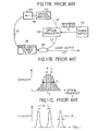
- Fig. 17 A shows an example of the composition of a conventional ring cavity-type mode-locked laser.
- the conventional ring cavity-type mode-locked laser which is shown in this figure consists of an optical modulator 102 to modulate the optical loss or phase with the specified frequency, a power supply 101 of the optical modulator 102, an optical amplifier 103 which amplifies the modulated optical signal, an optical isolator 104 which prescribes a direction ofthe propagation of optical signal and blocks offreflected light from optical components, an optical coupler 105 which outputs the amplified optical signal from the laser cavity, a wavelength tunable filter 106, and optical waveguides 107 which couple each ofthe above components optically (reference: H.
- the optical modulator 102 a modulator which utilizes electro-optical effect of LiNbO 3 , etc., is mainly used.
- the wavelength tunable filter 106 a dielectric multiple-film filter is mainly used.
- the optical waveguide 107 an optical fiber is mainly used.
- the optical amplifier 103 a rare earth-doped fiber amplifier which is doped with rare earths such as Er and Nd, semiconductor laser amplifier, etc., are mainly used.
- Fig 17B shows a typical spectral characteristic by the mode-locking
- Fig 17C shows its time characteristics.
- the optical modulator 102, the optical amplifier 103, the optical isolator 104, and the optical coupler 105 are coupled together into a ring shape with the optical waveguides 107 to form a ring cavity.
- f c c/L (c is the velocity of light).
- f m N ⁇ f c (N is an integer equal to or greater than one)
- a mode-locked oscillation is established, in which all longitudinal modes at frequency intervals of N ⁇ f c have their phases aligned as shown in Fig 17B, and the optical pulse train with the repetition period of 1/(N ⁇ f c ) is obtained as shown in Fig. 17C.
- This formula (2) expresses a mode-locking condition.
- the pulse width corresponds to the reciprocal of the oscillation spectral width d ⁇ which is determined with the envelope of multiple longitudinal mode spectra, and the center of this spectral envelope is a central wavelength (optical frequency ⁇ 0 ).
- the modulation frequency f m must be changed in response to the change of f c . That is, to achieve a mode-locking condition without being influenced by the change of the cavity length, the modulation frequency f m must be changed in response to the change of the cavity optical path length.
- the modulation frequency f m was fixed, it was difficult to respond to the change of the cavity optical path length due to the temperature change, etc., and previous mode-locked lasers, such as those described above, were not practical.
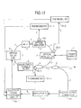
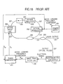
- Fig. 18 is a schematic diagram of this conventional method.
- the phase difference between a mode locked frequency component S m1 from power supply 201 and a mode locked frequency component S m2 of the electrical signal which was obtained from a laser output by photoelectric conversion, and the cavity optical path length is controlled by an optical delay line 208 in the cavity to suppress the change of the phase difference.
- the stability of the laser output mainly depended on the initialization of the cavity optical path length, considerably precise adjustments of the cavity optical path length were required at the beginning of laser operation.
- the mode locked frequency could not be easily changed.
- this method has a problem of low reliability because it does not monitor the stability of the laser output directly.
- the cavity optical path length is also changed to maintain the phase difference of the mode locking frequency component to be constant, and the laser operation shifts out of the mode-locking condition and the laser output becomes unstable.
- the output frequency of power supply is generally more than 2 GHz, high-speed operation is required for photoelectric converter 210, phase comparison receptacle 241 and peripheral circuits thereof.
- the present invention provides a method of stabilizing the output of a mode-locked laser, wherein the laser includes an optical modulating device, an optical path length changing device for electrically changing the optical path length of the cavity, and an optical amplifying device for amplifying the modulated optical signal output from the optical modulating device, which comprises a step of extracting at least one component of the relaxation oscillation frequency component and its harmonic components of the laser output as an error signal of feedback control; and a step of adjusting the optical path length by the optical path length changing device to set the optical path length to suppress the error signal below a predetermined value.
- the invention also provides apparatus for stabilizing the output of a mode-locked laser, which comprise an optical modulating device for modulating an input optical signal with a specified frequency, and an optical amplifying device for amplifying the modulated optical signal output from the optical modulating device; an optical delay device for electrically changing an optical path length of the cavity; an optical branching device for splitting a part of the laser output; an extracting device for converting the split optical signal into an electrical signal and for extracting at least one out of the relaxation oscillation frequency component and its harmonic components of the electrical signal as an error signal of feedback control; and an electrical signal processing device for inputting the error signal and for outputting a signal to drive the optical delay device to suppress the electrical power of the error signal below a predetermined value.
- This configuration may prevent a change of the laser cavity optical path length; and stable mode-locked operation can be realized thereby.
- Fig. 1 is a schematic diagram of a first preferred embodiment according to this invention.
- Figs. 2A, 2B, 2C and 2D are diagrams which show electrical power spectra of a mode-locking frequency component, a fundamental cavity frequency component, a relaxation oscillation frequency component, and its harmonic components in the mode-locked laser shown in Fig. 1.
- the section of Fig. 2A labeled "A” is shown enlarged in Fig. 2B by the section correspondingly labeled "A”.
- the section ofFig. 2B labeled "B” is shown enlarged in Fig. 2C by the section correspondingly labeled "B".
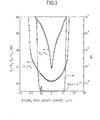
- Fig. 3 is a diagram which shows a measurement result of cavity optical path length dependence of electrical power ratios between the relaxation oscillation frequency component and the mode-locking frequency component P r /P m and between the supermode component and the mode-locking frequency component P S /P m , and an error rate.
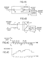
- Figs. 4A and 4B are schematic diagrams which show concrete examples of the optical delay line which is shown in Fig. 1, and Figs. 4C and 4D are diagrams which show an example of driving signal S D and time dependence of movement amount of each optical delay line in response to the driving signal S D , respectively.
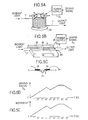
- Figs. 5A and 5B are schematic diagrams which show other concrete examples of the optical delay line which is shown in Fig. 1;
- Fig. 5C is a section drawing which shows the section of the part A-A in Fig. 5B; and
- Fig. 5D is a diagram which shows time dependence of movement amount of each optical delay line in response to driving signal S D .
- Fig. 6 is a diagram which shows the relationship between the optical path length of a cavity L and the electrical power of the relaxation oscillation frequency component P r .
- Fig. 7 is a schematic diagram which shows a composition example of the electrical signal processing circuit 13 which is shown in Fig. 1.
- Fig. 8 is a schematic diagram which shows a second preferred embodiment according to this invention.
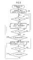
- Fig. 9 is a diagram which shows one example of a basic algorithm of operation of the electrical signal processing circuit 13 which is shown in Fig. 1.
- Fig. 10 is a schematic diagram of a third preferred embodiment according to this invention.
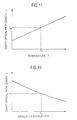
- Fig. 11 is a diagram which shows the relationship between the temperature of a cavity T and the optical path length L thereof.
- Fig. 12 is a schematic diagram which shows another example of the third preferred embodiment which is shown in Fig. 10.
- Fig 13 is a schematic diagram of a forth preferred embodiment according to this invention.
- Figs. 14A and 14B are schematic diagrams which show concrete examples ofthe wavelength tunable filter which is shown in Fig. 13.
- Fig. 15 is a diagram shows relation between the oscillating center wavelength ⁇ and the cavity optical path length L.
- Fig. 16 is the composition figure of a fifth preferred embodiment by this invention.
- Figs. 17A is a block diagram which shows a composition example of a conventional mode-locked laser
- Figs 17B and 17C are graphs which show operation characteristics of the laser shown in Fig. 17A.
- Fig. 18 is a block diagram which shows the composition example of the other conventional mode-locked laser.
- Fig. 1 is a diagram which shows a first preferred embodiment of the stabilizing apparatus of a ring cavity-type mode-locked laser, according to this invention.
- the ring cavity-type mode-locked laser which is shown in this figure has a power supply 1 for an optical modulator 2, an optical modulator 2, an optical amplifier 3, an optical isolator 4, an optical coupler 5 and a wavelength tunable filter 6, which respectively correspond to the power supply 101, the optical modulator 102, the optical amplifier 103, the optical isolator 104, the optical coupler 105 and the wavelength tunable filter 106 of the prior art, which is shown in Fig. 17A, and which are main components of a ring cavity-type mode-locked laser.
- the optical waveguide 7 is comprised of an optical fiber like the above-described conventional example (optical waveguide 107 in Fig. 17A) and/or a channel-type waveguide formed on a plane substrate, e.g. a planar lightwave circuit (reference: M. Kawachi et al., "Silica waveguide on silicon and their application to integrated-optical components", Opt. & Quantum Electron., vol. 2090, No. 23, pp. 391-417).
- a planar lightwave circuit reference: M. Kawachi et al., "Silica waveguide on silicon and their application to integrated-optical components", Opt. & Quantum Electron., vol. 2090, No. 23, pp. 391-417.
- the optical amplifier 3 is comprised of a rare earth-doped fiber amplifier or a semiconductor laser amplifier like a conventional example (optical amplifier 103), and/or a rare earth doped planar-type amplifier which is made by doping rare earth in the above planar lightwave circuit, etc., (reference: K. Hattori et al. "Erbium-doped silica-based planar-waveguide amplifier integrated with a 980/1530-nm WDM coupler", in Optical Fiber Communication 1993 Technical Digest Series, Volume 4, paper FB2).
- An optical coupler 9 splits the output light from the optical coupler 5 in two, and outputs one as the laser output, and outputs the other to a photoelectric converter 10.
- the photoelectric converter 10 changes an incident optical signal from the optical coupler 9 into an electrical signal, and outputs it to an amplifier 12 as an electrical signal S.
- the amplifier 12 extracts a relaxation oscillation frequency component signal S r from the electrical signal S and outputs it to an electrical signal processing circuit 13.
- the electrical signal processing circuit 13 outputs the driving signal S D to control the optical delay line 8 for suppressing the electrical power P r of the relaxation oscillation frequency component S r below a predetermined value. Then, the optical delay line 8 changes the optical path length of the cavity according to the driving signal S D .
- the relaxation oscillation frequency f r is expressed by the following formula (reference: "Lasers”, SIEGMAN, A.E., (University Science Books, Mill Valley, CA, 1986), chapter 25, p. 964).
- f r 1 2 ⁇ r - 1 ⁇ t c
- r is the ratio between a pumping rate to a higher level and a threshold pumping rate
- ⁇ is the lifetime of the higher level
- t c is a cavity decay time.
- f r becomes 10-500 kHz.
- the noise component of frequency f n below occurs.
- f n is lager than 0.
- the electrical power spectrum becomes as shown in Figs 2B and 2C.
- Fig 2B is an enlargement of a part (the part is the section labeled "A”.) of Fig. 2A, which is enlarged in the axis of frequency; and Fig. 2C is a diagram which is drawn by enlarging a part (the section labeled "B") of Fig. 2B in the same way.
- the value of the electrical power P r of this relaxation oscillation frequency component changes sensitively in response to the detuning from the mode-locking condition (the change of cavity optical path length L).
- Fig. 3 shows a measurement result of relation between the optical path length change of the cavity and the electrical power P r of the relaxation oscillation frequency component at a mode-locked Er doped fiber ring laser.
- the ratio between P r and the electrical power P m of the mode locked frequency component is used.
- BER bit error rate
- This error rate depends on the signal-to-noise ratio of the optical signal light.
- the signal-to-noise ratio of the laser output deteriorates, and the error rate increases.
- the error rate 10 -10 or less is required.
- the allowable range of the optical path length change to keep a bit error rate less than 10 -10 is about ⁇ 50 ⁇ m and the relaxation oscillation frequency component P r changes more than approximately 10 dB in response to the optical path length change of 10 ⁇ m. Therefore, sensitive control ofthe cavity optical path length can be realized, which prevents the optical path length from changing and leads stable mode-locked operation by extracting a relaxation oscillation frequency component and using it as an error signal (see Fig. 2D).
- the amplifier 12 is adopted in the above explanation, if the relaxation oscillation frequency component is sufficiently large to be used for the control of the succeeding stages without amplifying, a band pass filter may be used instead of the amplifier 12.
- the amplifier 12 selects and amplifies only the relaxation oscillation frequency component S r as the error signal in the above explanation, but harmonic frequency components of the relaxation oscillation frequency component may be contained additionally as the error signal.
- the electrical power spectrum of the electrical signal S which is converted from the laser output light with the photoelectric converter 10 As for the electrical power spectrum of the electrical signal S which is converted from the laser output light with the photoelectric converter 10; the electrical power of the direct current component and the mode-locked frequency components (including harmonic frequency components) are almost constant regardless of a change of the cavity length; and their levels are higher than the relaxation oscillation frequency component by more than 70 dB in a stable condition.
- the supermode component as well as the relaxation oscillation frequency component changes in response to a change of the cavity length, but this change is small (see dotted line (P s /P m ) in Fig. 3).
- the band of the amplifier 12 (or the band pass filter) to be set to pass only the relaxation oscillation frequency and its harmonic frequencies, and to be set not to pass the direct current component, the mode-locking frequency components (including harmonic frequency components), and supermode components. That is, when the relaxation oscillation frequency f r is lower than the fundamental cavity frequency f c ; supposing that f L and f H are the lower and the upper bound frequencies of the band of the amplifier 12 (or the band pass filter), respectively; these frequencies may be arranged in the following order.
- Figs. 4A and 4B show optical delay lines which are concrete examples of the optical delay line 8 shown in Fig. 1.
- Each of optical delay lines in Figs. 4A and 4B utilizes two optical waveguides optionally coupled with lenses. These optical delay lines comprise an electrical stage 21 which is electrically moved in the directions of the arrow "A", optical lenses 20, power supply 35, right-angle mirrors 22 such as a triangular prism, etc.
- the optical delay line in Fig. 4B can control optical path length by moving the right-angle mirror 22 along the beam direction in the same way.
- the electric driving stage 21 of these optical delay lines may be driven by pulse driving signals.
- the direction of movement is changed according to the polarity of input electricity pulses as shown in Fig. 4C; and the amount of movement is determined by the number of the input electricity pulses, which are input as the driving signal S D .
- Fig. 5A shows another example of the optical delay line 8 which changes the optical path length by elongating an optical waveguide with tensile force.
- This optical delay line changes the optical path length by changing a tensile force onto the optical waveguide 7 such as a relatively longer optical fiber, which is wound on a drum 23 which is made ofa piezoelectric device; and the diameter of the drum 23 is varied by changing the voltage output from power supply 35.
- FIG. 5B is a diagram which shows another example of the optical delay line 8 which changes the optical path length of an optical waveguide by electrically varying the refractive index of the optical waveguide.
- This optical delay line comprises a substrate 24, an optical waveguide 25 whose refractive index can be changed electrically, and electrodes 26.
- Electric field E occurs in the optical waveguide 25 by applying a voltage between two electrodes 26; and the refractive index of the optical waveguide 25 changes; and then the optical path length changes (see Fig. 5C).
- Ferroelectric substances such as LiNbO 3 , which provide electro-optical effect, may be used as the optical waveguide 26.
- the amount of movement is determined by absolute values of input electrical signals (driving signal S D ) as shown in Figs. 5D and 5E.
- feedback control of the cavity length of a mode-locked laser can be achieved by using at least one out of optical delay lines which are shown in Figs 4A, 4B, 5A, and 5B.
- the driving signal S D to be input into the optical delay line 8 varies depending on the type of the optical delay line 8 to be used.
- the electrical power Pr of the relaxation oscillation frequency component is measured during the time when the cavity optical path length is swept at some range by changing the driving signal S D , i.e., by changing the number of the driving pulse signals.
- This sweep range of the optical path length may be predetermined to be sufficiently wider than the estimated maximum detuning from the optical path length at the mode-locking condition; the detuning occurs by temperature change, etc.
- Fig. 6 is a diagram which shows an example of the typical relationship between the electrical power P r of the relaxation oscillation frequency component and the optical path length L, which is obtained by such a sweep.
- the driving signal value S D may be continuously 0 after that until the electrical power P r of the relaxation oscillation frequency component has started changing.
- the optical delay line driving signal + ⁇ S D is input into the optical delay line 8 to increase the optical path length (+ ⁇ L) at first (step 302).
- ⁇ S D and ⁇ L express a differential change of the driving signal S Da and a differential change of the optical path length L, respectively.
- step 304 the driving signal change of + ⁇ S D is re-input to further increase the optical path length L (step 302). This process is repeated until the electrical power P r is below the electrical power limit value P limit (steps 302-304).
- P r is less than P limit
- the optical delay line driving signal S D is restored to 0; and detection of the electrical power P r of the relaxation oscillation frequency component is continued (step 303 ⁇ step 301).
- step 304 if the electrical power P r increases (step 304) at the time when the optical delay line driving signal + ⁇ S D is input to the optical delay line 8 (step 302), polarity ofthe optical delay line driving signal is changed to - ⁇ S D to decrease the optical path length L by ⁇ L (- ⁇ L) (step 305).
- step 305 This process is repeated (steps 305-307) in the manner described above until P r is less than P limit , and then the optical delay line driving signal S D is restored to 0 at that time (step 306 ⁇ step 301). With this process, the change ofthe cavity optical path length can be suppressed and stable operation can be maintained.
- the optical delay lines in Figs. 5A and 5B are different from the optical delay lines in Figs. 4A and 4B in the following point. That is, since the amount of optical delay is determined according to the absolute values of the driving signals, it is required to maintain the driving signal value S D as S Da continuously to maintain the optical delay amount just as it is.
- the optical delay line driving signal S D is changed from S D to S D + ⁇ S D (i.e., L ⁇ L+ ⁇ L) and the change ofthe electrical power P r is monitored. If the electrical power P r decreases after that, the above-described process to increase S D is repeated further, until the electrical power P r is below the maximum allowable electrical power P limit . When P r is less than P limit , the increment of the optical delay line driving signal S D is stopped.
- the optical delay line driving signal S D is changed to S D - ⁇ S D (L ⁇ L- ⁇ L); and this process is repeated until P r is less than P limit like the above. With this process, the cavity optical path length change can be suppressed and stable operation can be achieved.
- Fig. 7 shows a concrete example of the inside configuration of the electrical signal processing circuit 13 shown in Fig. 1.
- the electrical signal processing circuit 13 which is shown in this figure comprises a calculators 16 such as a microcomputer, an analog/digital converter 15, and a digital/analog converter 17.
- the analog/digital converter 15 changes the relaxation oscillation frequency component signal S r , which is an analog signal, into a digital signal.
- the optical delay line driving signal is determined to have a predetermined polarity and a predetermined number of pulses or a predetermined level, according to the above-described algorithm, by the calculator 16. In the case of using the optical delay line in Figs.
- the optical delay line driving signal S D is input from the calculator 16 directly to the optical delay line 8.
- the analog optical delay line driving signal S D is generated using the digital/analog converter 17.
- this preferred embodiment extracts the relaxation oscillation frequency component signal Sr out of the electrical signal S output from the photoelectric converter 10 using the amplifier 12 (the a band pass filter); and it feeds back the driving signal S D from the electrical signal processing circuit 13 into the optical delay line 8, which is installed in the cavity, to suppress the electrical power P r of the relaxation oscillation frequency component; and the embodiment can maintain the cavity optical path length to be constant and can realize a stable mode-locked laser operation.
- Fig. 8 shows another preferred embodiment of the stabilizing apparatus of a Fabry-Perot cavity-type mode-locked laser according to the invention. Identical reference numerals are attached, in this figure, to the respective elements, which correspond to those in Fig. 1.
- the Fabry-Perot cavity-type mode-locked laser shown in this figure further comprises an optical reflector 27 which reflects most of the incident light.
- This preferred embodiment has basically the same configuration as the first preferred embodiment, except that the type of cavity is a Fabry-Perot type; and stable operation can in principle be achieved by processes similar to those in the first preferred embodiment.
- the optical delay line driving signal is fed back into the optical delay line in the cavity to suppress the electrical power of the relaxation oscillation frequency component of the electrical signal, which is converted from the optical signal output from the mode-locked laser; and the change of the cavity length, which is caused by temperature change, etc., can be detected with good sensitivity. Therefore, the optical delay line can be controlled with extraordinary precision and good stabilization of the output of the mode-locking laser can be realized.
- Fig. 10 is a diagram which shows another preferred embodiment of a ring cavity-type mode-locked laser stabilizing apparatus and method according to the invention.
- This third preferred embodiment further comprises, in addition to the elements of the first preferred embodiment, a temperature sensor 50 and a thermometer 51, which converts the output of the temperature sensor 50 into a voltage or an electrical current; and the other components are the same as those of the first preferred embodiment.
- a temperature sensor 50 a platinum resistor and a thermistor, whose resistance value changes depending on temperature T, etc., can be used.
- This third preferred embodiment uses a method to fix the initial value L 1 of the cavity optical path length of the mode-locked laser automatically by additional temperature detection and then to stabilize the output of the mode-locked lasers by controlling the cavity optical path length more precisely to suppress the relaxation oscillation frequency components, which is explained in the first preferred embodiment,.
- the cavity optical path length L is elongated (or shortened) due to thermal expansion when the temperature T of the cavity increases (or decreases).
- T and L can be approximately expressed by the following formula by supposing that ⁇ is a coefficient of thermal expansion of the cavity length, T s is a certain standard temperature, and L S is the cavity optical path length at which the mode-locking condition is fulfilled at the standard temperature T S .
- L L S ⁇ 1 + ⁇ ( T - T S ) ⁇
- thermal expansion coefficient ⁇ is about 10 -5 (1/°C).
- T minus T S is 1 (°C) and the standard cavity optical path length L S is 100 m
- the cavity optical path length increases by about 1 mm. Therefore, in that case, by decreasing the cavity optical path length by the same length with the optical delay line 8, the change of the cavity optical path length can be compensated.
- the control precision of the cavity optical path length by this temperature detection can be calculated with formula (7).
- the precision ⁇ T of a thermometer is about 10 -2 (°C).
- the control precision ⁇ L of the cavity optical path length is, therefore, about 10 ⁇ m.
- This precision ⁇ L is within the pull-in range (about ⁇ 50 ⁇ m) of the relaxation oscillation frequency component suppression method according to the invention; i.e., the pull-in range is a range at which the mode-locking condition is able to be established by the methods according to the invention (see Fig. 3). Therefore, even if the initial value of the cavity optical path length which is set by the temperature detection process above is out of the stable operation range shown in Fig. 6, the cavity optical path length can be automatically pulled-in into the stable operation range according to the algorithm (see Fig. 9) of the relaxation oscillation frequency component suppression method.
- temperatures at more than one of the positions may be detected in the cavity using a plurality of temperature sensors; sensors 50-1, 50-2, and 50-3 and thermometers 51-1, 51-2, and 51-3 are used in this example.
- signal processing can be proceeded in the electrical signal processing circuit 13a-1 based on an average temperature T ave , which may be defined by the following formula.
- Each temperature coefficient k i of formula (9) may be obtained by measuring the relationship between the temperatures (T 1 , T 2 ,..., T i ) of each position and the cavity optical path length L beforehand; and by setting the temperature coefficients (k 1 , k 2 , ..., k i ) to make the relationship between average temperature T ave and the cavity optical path length L to be linear.
- Fig. 13 is a diagram which shows another preferred embodiment of the ring cavity-type mode-locked laser stabilization method and apparatus according to the invention.
- This preferred embodiment comprises a wavelength tunable filter 6B which can control a filtering wavelength in response to an electrical signal S ⁇ from the electrical signal processing circuit 13b; and the embodiment can electrically control the oscillation wavelength of the mode-locked laser.
- the other components are the same as those of the first preferred embodiment.
- Figs. 14A and 14B show concrete examples of the wavelength tunable filter 6B.
- the wavelength tunable filter 6b-1 which is shown in Fig. 14A comprises two optical lenses 20, an optical filter board 30 which consists of a dielectric multiple film, etc., an electrical drive stage 31 which turns the optical filter board 30, and power supply 32 for driving the stage.
- the wavelength tunable filter 6b-1 can electrically control the filtering wavelength by turning optical filter board 30 via the electric stage 31 to change the angle ⁇ between the board surface and the beam axis.
- the wavelength tunable filter 6b-2 which is shown in Fig. 14B comprises two optical lenses 20, liquid crystal 33, mirrors 34, substrates 35, and a power supply 36 for driving the liquid crystal 33.
- the wavelength tunable filter 6b-2 also can control the filtering wavelength electrically by changing electric fields applied to liquid crystal 33 to change the refractive index n of liquid crystal 33.
- the method of this preferred embodiment may be used when the oscillation wavelength of the mode-locked laser is changed.
- an initial value L 1 of the cavity optical path length is determined automatically according to an arbitrarily set wavelength; after that, the cavity optical path length is controlled precisely by the above-described relaxation oscillation frequency component suppression method; and the output of the mode-locked laser can be stabilized thereby.
- Fig. 15 There is the general relationship as shown in Fig. 15 between the oscillation wavelength ⁇ of a mode-locked laser and the cavity optical path length L.
- the cavity optical path length L decreases (or increases) due to the wavelength dispersion of the refractive index of the cavity when the oscillation wavelength ⁇ increases (or decreases).
- This change ⁇ L of the cavity optical path length may be expressed by the following formula (10) based on formula (1).
- the relationship between the wavelength and the refractive index may be obtained by the following formula according to the Sellmeier equation (reference: G. P. Agrawal, "Nonlinear fiber optics", Academic Press, chapter 1, p. 7)
- a j and ⁇ i are constants which are determined by the cavity component medium.
- the cavity optical path length L is set at a value L s at which the mode-locking condition is fulfilled in a standard wavelength ⁇ s beforehand.
- each physical length h j and each wavelength dispersion ⁇ n i ( ⁇ )/ ⁇ of the refractive index of each component is also measured beforehand.
- the wavelength tunable filter 6B is driven by the electrical signal processing circuit 13b to set the oscillation wavelength ⁇ to be a desired value.
- resultant cavity optical path length from the above-described process is used as an initial value.
- the cavity optical path length is controlled precisely to maintain the cavity optical path length to be constant like first and the second preferred embodiments by the relaxation oscillation frequency component suppression method.
- formula (12) may be transformed to the following formula.
- the control precision of the optical path length by this wavelength change can be calculated from formulas (10) and (11).
- the refractive index wavelength dispersion ⁇ n( ⁇ )/ ⁇ is about -10 -5 (1/nm); and generally, the wavelength precision ⁇ of an optical filter is about 10 -1 (nm).
- the control precision ⁇ L ofthe optical path length may be obtained to be about 30 ⁇ m from formula (13).
- this preferred embodiment provides a method for stabilizing the laser output by using the relaxation oscillation frequency component suppression method after controlling the optical path length of the cavity in response to the setting value of the oscillation wavelength.
- stabilization of the mode-locked laser output can be established quickly and automatically at an arbitrarily selected wavelength.
- a ring cavity-type mode-locked laser is used at this preferred embodiment, a Fabry-Perot cavity-type mode-locked lasers also can be applied to this embodiment.
- Fig. 16 is a diagram which shows another preferred embodiment of a ring cavity-type mode-locked laser stabilizing apparatus and method thereby according to the invention.
- This preferred embodiment comprises a combination of the method which is automatic setting of the initial value of the cavity optical path length by the temperature detection in the third preferred embodiment and the method which is automatic setting of the initial value of the cavity optical path length in response to a setting value of the oscillation wavelength in the fourth preferred embodiment.
- the cavity optical path length L is set at a value L s which fulfills the mode-locking condition in a certain standard oscillation wavelength ⁇ s and a standard temperature T S beforehand.
- Physical lengths h i and wavelength dispersions ⁇ n( ⁇ )/ ⁇ of the refractive indexes of the components are also measured beforehand.
- the wavelength tunable filter 6b is driven by the electrical signal processing circuit 13c to set the wavelength at a desired value ⁇ , whereas the temperature T ofthe cavity detected with the temperature sensor 50 is input to the electrical signal processing circuit 13.
- the electrical signal processing circuit 13c outputs a driving signal to the optical delay line 8 to compensate the total cavity optical path length change ⁇ L total .
- the optical delay change ⁇ D in this case is shown by the following formula based on formulas (8) and (13).
- the resultant cavity optical path length is used as an initial value.
- the cavity optical path length is maintained to be constant by the relaxation oscillation frequency component suppression method, like the first and the second preferred embodiments.
- this preferred embodiment provides a method for stabilizing the mode-locked laser output by the relaxation oscillation frequency component suppression method, after controlling the optical path length of the cavity according to a setting value of the oscillation wavelength and to the temperature of the cavity.
Landscapes
- Physics & Mathematics (AREA)
- Electromagnetism (AREA)
- Engineering & Computer Science (AREA)
- Plasma & Fusion (AREA)
- Optics & Photonics (AREA)
- Lasers (AREA)
- Light Guides In General And Applications Therefor (AREA)
- Optical Integrated Circuits (AREA)
Applications Claiming Priority (3)
| Application Number | Priority Date | Filing Date | Title |
|---|---|---|---|
| JP5288/95 | 1995-01-17 | ||
| JP00528895A JP3234429B2 (ja) | 1995-01-17 | 1995-01-17 | モード同期レーザの動作安定化装置 |
| JP528895 | 1995-01-17 |
Publications (3)
| Publication Number | Publication Date |
|---|---|
| EP0723320A2 true EP0723320A2 (de) | 1996-07-24 |
| EP0723320A3 EP0723320A3 (de) | 1997-10-22 |
| EP0723320B1 EP0723320B1 (de) | 2004-06-09 |
Family
ID=11607061
Family Applications (1)
| Application Number | Title | Priority Date | Filing Date |
|---|---|---|---|
| EP96400101A Expired - Lifetime EP0723320B1 (de) | 1995-01-17 | 1996-01-16 | Verfahren und Vorrichtung zur Stabilisierung eines modengekoppelten Lasers |
Country Status (4)
| Country | Link |
|---|---|
| US (1) | US5646774A (de) |
| EP (1) | EP0723320B1 (de) |
| JP (1) | JP3234429B2 (de) |
| DE (1) | DE69632652T2 (de) |
Cited By (8)
| Publication number | Priority date | Publication date | Assignee | Title |
|---|---|---|---|---|
| EP0910142A3 (de) * | 1997-10-14 | 2000-03-01 | Ando Electric Co., Ltd. | Optischer Impulsgeber |
| WO2002007273A3 (en) * | 2000-07-17 | 2002-07-18 | Calmar Optcom Inc | Fiber laser stabilization |
| EP0987518A3 (de) * | 1998-09-17 | 2003-01-08 | LITEF GmbH | Faseroptischer Kreisel mit geschlossener Regelschleife und Kompensation des Shupe-Effekts |
| EP1041748A3 (de) * | 1999-03-30 | 2004-06-09 | Oki Electric Industry Co., Ltd. | Frequenzstabilisatoreinrichtung für eine Lichtquelle für die optische Kommunikation |
| US6839363B2 (en) | 2001-03-16 | 2005-01-04 | Calmar Optcom, Inc. | Digital control of actively mode-locked lasers |
| US6845108B1 (en) | 2001-05-14 | 2005-01-18 | Calmar Optcom, Inc. | Tuning of laser wavelength in actively mode-locked lasers |
| RU2480876C2 (ru) * | 2010-07-09 | 2013-04-27 | Общество С Ограниченной Ответственностью "Научно-Техническое Объединение "Ирэ-Полюс" | Лазерная система с динамически стабилизируемой релаксирующей длиной волны и способ ее функционирования |
| CN119651341A (zh) * | 2024-11-29 | 2025-03-18 | 北京航空航天大学 | 用于serf磁强计激光失谐稳频的法布里-珀罗腔锁腔方法 |
Families Citing this family (46)
| Publication number | Priority date | Publication date | Assignee | Title |
|---|---|---|---|---|
| US5778016A (en) | 1994-04-01 | 1998-07-07 | Imra America, Inc. | Scanning temporal ultrafast delay methods and apparatuses therefor |
| US5808770A (en) * | 1995-12-29 | 1998-09-15 | Lucent Technologies, Inc. | Method and apparatus for using on-off-keying using laser relaxation oscillation |
| US6493125B1 (en) * | 1998-02-25 | 2002-12-10 | Oki Electric Industry Co., Ltd. | Apparatus for stabilizing light source frequency |
| JP3740291B2 (ja) | 1998-08-24 | 2006-02-01 | 日本オプネクスト株式会社 | 光送信器 |
| US6175579B1 (en) | 1998-10-27 | 2001-01-16 | Precision Light L.L.C. | Apparatus and method for laser frequency control |
| KR100327899B1 (ko) | 1999-11-03 | 2002-03-09 | 오길록 | 모드 로킹 광섬유 레이저 안정화 장치 및 그 방법 |
| KR100325687B1 (ko) * | 1999-12-21 | 2002-02-25 | 윤덕용 | 주입된 비간섭성 광에 파장 잠김된 페브리-페롯 레이저다이오드를 이용한 파장분할 다중방식 광통신용 광원 |
| US6996136B1 (en) | 2000-05-05 | 2006-02-07 | The United States Of America As Represented By The Secretary Of The Navy | Ultrashort-pulse fiber laser with a dispersion-managed cavity |
| JP2002077051A (ja) * | 2000-08-31 | 2002-03-15 | Fujitsu Ltd | 光信号処理装置 |
| WO2002025783A2 (en) * | 2000-09-22 | 2002-03-28 | Calmar Optcom, Inc. | Actively mode-locked fiber laser with controlled chirp output |
| JP3726676B2 (ja) * | 2000-11-28 | 2005-12-14 | 日本電気株式会社 | 外部共振器型モード同期半導体レーザ装置 |
| KR100353846B1 (ko) * | 2000-12-26 | 2002-09-28 | 한국전자통신연구원 | 모드 로킹 광섬유 레이저 공진 장치 |
| US7027472B2 (en) * | 2001-07-19 | 2006-04-11 | Axsun Technologies, Inc. | Fixed wavelength single longitudinal mode coolerless external cavity semiconductor laser system |
| JP3650818B2 (ja) * | 2001-10-02 | 2005-05-25 | 独立行政法人情報通信研究機構 | 光パルスレーザ装置 |
| JP3986824B2 (ja) * | 2001-12-28 | 2007-10-03 | 富士通株式会社 | 光フィルタの制御方法及び制御装置並びに光ノード装置 |
| JP3747242B2 (ja) * | 2002-03-14 | 2006-02-22 | 独立行政法人情報通信研究機構 | 光パルス繰り返し周波数逓倍装置 |
| KR100515259B1 (ko) * | 2002-05-03 | 2005-09-15 | 한국과학기술원 | 파장 가변 광원 구현 방법 및 장치와 이 광원을 이용한 파장분할 다중방식 광전송 장치 |
| US6935444B2 (en) * | 2003-02-24 | 2005-08-30 | Baker Hughes Incorporated | Superabrasive cutting elements with cutting edge geometry having enhanced durability, method of producing same, and drill bits so equipped |
| US20040190907A1 (en) * | 2003-03-25 | 2004-09-30 | General Instrument Corporation | All-optical reference clock for generating stable RF comb spectrum |
| US20040213303A1 (en) * | 2003-04-22 | 2004-10-28 | General Instrument Corporation | Optical frequency synthesizer |
| KR100955129B1 (ko) * | 2003-05-30 | 2010-04-28 | 정보통신연구진흥원 | 비간섭성 광대역 광원을 이용한 파장분할다중방식 수동형 광 네트워크 구현 방법 |
| US7848655B2 (en) * | 2003-08-28 | 2010-12-07 | Telcordia Technologies, Inc. | Mode-locked optical amplifier as a source for a wdm-WDM hierarchy architecture |
| US7313157B2 (en) | 2003-12-19 | 2007-12-25 | Novera Optics, Inc. | Integration of laser sources and detectors for a passive optical network |
| US7492795B1 (en) | 2004-01-06 | 2009-02-17 | University Of Central Florida Research Foundation, Inc. | Ultralow noise mode-locked laser and RF sinewave source |
| WO2005081236A1 (en) * | 2004-02-09 | 2005-09-01 | Koninklijke Philips Electronics N.V. | System for reducing feedback noise due to relaxation oscillation in optical data recording reproducing systems using optimized external cavity |
| JP4527479B2 (ja) * | 2004-09-10 | 2010-08-18 | サンテック株式会社 | 波長走査型ファイバレーザ光源 |
| US20060222024A1 (en) * | 2005-03-15 | 2006-10-05 | Gray Allen L | Mode-locked semiconductor lasers with quantum-confined active region |
| US20060227818A1 (en) * | 2005-04-12 | 2006-10-12 | Nl-Nanosemiconductor Gmbh | Fundamental-frequency monolithic mode-locked laser including multiple gain absorber pairs |
| KR100698766B1 (ko) * | 2005-09-07 | 2007-03-23 | 한국과학기술원 | 파장분할 다중방식 수동형 광 가입자 망 시스템에 사용되는장애 위치 감시 장치 및 이를 구비한 파장분할 다중방식수동형 광 가입자 망 시스템 |
| KR100785436B1 (ko) | 2005-09-20 | 2007-12-13 | 한국과학기술원 | 방송 서비스와 통신 서비스를 융합한 파장분할 다중방식수동형 광 가입자망 |
| US8571410B2 (en) * | 2006-10-11 | 2013-10-29 | Novera Optics, Inc. | Mutual wavelength locking in WDM-PONS |
| US8036537B2 (en) * | 2007-06-13 | 2011-10-11 | International Business Machines Corporation | Optical pulse amplication apparatus and method |
| JP4953943B2 (ja) * | 2007-07-02 | 2012-06-13 | 株式会社アドバンテスト | モードロックレーザ装置 |
| US7983314B2 (en) * | 2008-02-13 | 2011-07-19 | General Photonics Corporation | Polarization stable lasers |
| DE102008045359B3 (de) * | 2008-08-22 | 2010-05-20 | Deutsches Elektronen-Synchrotron Desy | Detektion von Veränderungen eines Zeitabstands optischer oder elektrischer Signale |
| KR101155541B1 (ko) * | 2010-11-29 | 2012-06-18 | 한국과학기술원 | 광섬유 펨토초 레이저의 모드잠금 자동화 장치 |
| JP5975461B2 (ja) * | 2012-02-03 | 2016-08-23 | 大学共同利用機関法人 高エネルギー加速器研究機構 | レーザーコンプトン散乱装置 |
| CN103323943B (zh) * | 2013-06-06 | 2015-09-16 | 珠海保税区光联通讯技术有限公司 | 可调光学滤波器 |
| EP2866314A1 (de) | 2013-10-24 | 2015-04-29 | ETH Zurich | Verfahren und Vorrichtung zur Frequenzsteuerung und Stabilisierung eines Halbleiterlasers |
| US9300109B2 (en) * | 2014-01-13 | 2016-03-29 | Raytheon Company | Serial servo system and method for controlling an optical path length and a repetition frequency of a mode-locked laser |
| KR101682593B1 (ko) * | 2015-05-26 | 2016-12-05 | 한국과학기술연구원 | 단일 펄스 레이저 장치 |
| JP6545020B2 (ja) * | 2015-06-30 | 2019-07-17 | 富士通株式会社 | 変調光源 |
| US10097277B2 (en) | 2016-02-19 | 2018-10-09 | Futurewei Technologies, Inc. | Optical modulator bias locking |
| JP6621026B2 (ja) * | 2016-09-06 | 2019-12-18 | 日本電信電話株式会社 | 波長掃引光源の評価方法 |
| KR102044378B1 (ko) * | 2018-11-21 | 2019-11-13 | 한국과학기술연구원 | 이중 트리거를 이용한 단일 펄스 레이저 장치 |
| CN116260039B (zh) * | 2023-04-04 | 2025-12-12 | 北京航空航天大学 | 一种重频环境稳定的脉冲激光生成方法和系统 |
Family Cites Families (9)
| Publication number | Priority date | Publication date | Assignee | Title |
|---|---|---|---|---|
| US3611187A (en) * | 1969-05-14 | 1971-10-05 | Sylvania Electric Prod | Mode-locked laser modulated by a train of stabilized nondamped relaxation pulses |
| US3584312A (en) * | 1969-10-20 | 1971-06-08 | Raytheon Co | Spikeless single-mode laser |
| JP2612593B2 (ja) * | 1988-06-16 | 1997-05-21 | 日本電信電話株式会社 | 光ファイバレーザ装置 |
| US5212711A (en) * | 1992-02-18 | 1993-05-18 | At&T Bell Laboratories | Harmonically mode-locked laser |
| DE69404129T2 (de) * | 1993-02-25 | 1998-01-08 | British Telecommunications P.L.C., London | Stabilisierung eines modengekoppelten faserringlasers |
| DE4317667A1 (de) * | 1993-05-27 | 1994-12-01 | Sel Alcatel Ag | Aktiv modengekoppelter Faserlaser |
| US5513194A (en) * | 1994-06-30 | 1996-04-30 | Massachusetts Institute Of Technology | Stretched-pulse fiber laser |
| DE4425809A1 (de) * | 1994-07-21 | 1996-01-25 | Sel Alcatel Ag | Modengekoppelter Faserringlaser |
| DE4441133A1 (de) * | 1994-11-21 | 1996-05-23 | Sel Alcatel Ag | Modengekoppelter Faserlaser |
-
1995
- 1995-01-17 JP JP00528895A patent/JP3234429B2/ja not_active Expired - Lifetime
-
1996
- 1996-01-16 US US08/585,566 patent/US5646774A/en not_active Expired - Lifetime
- 1996-01-16 EP EP96400101A patent/EP0723320B1/de not_active Expired - Lifetime
- 1996-01-16 DE DE69632652T patent/DE69632652T2/de not_active Expired - Fee Related
Cited By (10)
| Publication number | Priority date | Publication date | Assignee | Title |
|---|---|---|---|---|
| EP0910142A3 (de) * | 1997-10-14 | 2000-03-01 | Ando Electric Co., Ltd. | Optischer Impulsgeber |
| US6108465A (en) * | 1997-10-14 | 2000-08-22 | Ando Electric Co., Ltd. | Optical pulse generator |
| EP0987518A3 (de) * | 1998-09-17 | 2003-01-08 | LITEF GmbH | Faseroptischer Kreisel mit geschlossener Regelschleife und Kompensation des Shupe-Effekts |
| EP1041748A3 (de) * | 1999-03-30 | 2004-06-09 | Oki Electric Industry Co., Ltd. | Frequenzstabilisatoreinrichtung für eine Lichtquelle für die optische Kommunikation |
| WO2002007273A3 (en) * | 2000-07-17 | 2002-07-18 | Calmar Optcom Inc | Fiber laser stabilization |
| US6567438B2 (en) | 2000-07-17 | 2003-05-20 | Calmar Optcom, Inc. | Active and low-power laser stabilization |
| US6839363B2 (en) | 2001-03-16 | 2005-01-04 | Calmar Optcom, Inc. | Digital control of actively mode-locked lasers |
| US6845108B1 (en) | 2001-05-14 | 2005-01-18 | Calmar Optcom, Inc. | Tuning of laser wavelength in actively mode-locked lasers |
| RU2480876C2 (ru) * | 2010-07-09 | 2013-04-27 | Общество С Ограниченной Ответственностью "Научно-Техническое Объединение "Ирэ-Полюс" | Лазерная система с динамически стабилизируемой релаксирующей длиной волны и способ ее функционирования |
| CN119651341A (zh) * | 2024-11-29 | 2025-03-18 | 北京航空航天大学 | 用于serf磁强计激光失谐稳频的法布里-珀罗腔锁腔方法 |
Also Published As
| Publication number | Publication date |
|---|---|
| JPH08195519A (ja) | 1996-07-30 |
| EP0723320B1 (de) | 2004-06-09 |
| EP0723320A3 (de) | 1997-10-22 |
| DE69632652T2 (de) | 2005-06-16 |
| US5646774A (en) | 1997-07-08 |
| DE69632652D1 (de) | 2004-07-15 |
| JP3234429B2 (ja) | 2001-12-04 |
Similar Documents
| Publication | Publication Date | Title |
|---|---|---|
| US5646774A (en) | Mode-locked laser stabilizing method and apparatus | |
| US6738408B2 (en) | Mode-locked laser apparatus | |
| US6775447B2 (en) | All fiber low noise supercontinuum source | |
| Collings et al. | Short cavity erbium/ytterbium fiber lasers mode-locked with a saturable Bragg reflector | |
| US6845108B1 (en) | Tuning of laser wavelength in actively mode-locked lasers | |
| US7719666B2 (en) | Distributed optical fiber sensor | |
| US6901087B1 (en) | Broadband laser source | |
| Han et al. | Novel multiwavelength erbium-doped fiber and Raman fiber ring lasers with continuous wavelength spacing tunability at room temperature | |
| Wey et al. | Performance characterization of a harmonically mode-locked erbium fiber ring laser | |
| Li et al. | Tunable narrow-linewidth fiber laser based on the acoustically controlled polarization conversion in dispersion compensation fiber | |
| Song et al. | Switchable and tunable dual-wavelength ultrashort pulse generation in a passively mode-locked erbium-doped fiber ring laser | |
| JPH09246638A (ja) | モード同期ファイバレーザ動作安定化法 | |
| Cui et al. | Switchable generation of multi-wavelength continuous wave and square-wave pluses in a bidirectional Erbium-doped fiber laser | |
| Kean et al. | Experimental evaluation of a fibre Raman oscillator having fibre grating reflectors | |
| JP3183021B2 (ja) | モード同期レーザ装置 | |
| Hu et al. | In-fiber dispersion compensated polarizer and mode-locked fiber laser application | |
| JP3345794B2 (ja) | モード同期レーザ装置 | |
| Suche et al. | Integrated optical spectrum analyzer with internal gain | |
| Ali et al. | Single-pump multiwavelength hybrid Raman-EDF laser using a non-adiabatic microfiber interferometer | |
| Adel | Pulsed fiber lasers | |
| WO2008144849A1 (en) | A mode-locked laser | |
| Zhang et al. | Stable single-mode multiwavelength optical fiber laser | |
| GOMES | Hybrid electronically addressable random fiber laser | |
| Galindez et al. | Integral temperature hybrid laser sensor | |
| Nakajima et al. | All-fiber-based mode-filtering technique with high side-mode suppression ratio and high multiplication factor |
Legal Events
| Date | Code | Title | Description |
|---|---|---|---|
| PUAI | Public reference made under article 153(3) epc to a published international application that has entered the european phase |
Free format text: ORIGINAL CODE: 0009012 |
|
| AK | Designated contracting states |
Kind code of ref document: A2 Designated state(s): DE FR GB |
|
| PUAL | Search report despatched |
Free format text: ORIGINAL CODE: 0009013 |
|
| AK | Designated contracting states |
Kind code of ref document: A3 Designated state(s): DE FR GB |
|
| 17P | Request for examination filed |
Effective date: 19971224 |
|
| 17Q | First examination report despatched |
Effective date: 20021128 |
|
| GRAP | Despatch of communication of intention to grant a patent |
Free format text: ORIGINAL CODE: EPIDOSNIGR1 |
|
| GRAS | Grant fee paid |
Free format text: ORIGINAL CODE: EPIDOSNIGR3 |
|
| GRAA | (expected) grant |
Free format text: ORIGINAL CODE: 0009210 |
|
| AK | Designated contracting states |
Kind code of ref document: B1 Designated state(s): DE FR GB |
|
| REG | Reference to a national code |
Ref country code: GB Ref legal event code: FG4D |
|
| REF | Corresponds to: |
Ref document number: 69632652 Country of ref document: DE Date of ref document: 20040715 Kind code of ref document: P |
|
| ET | Fr: translation filed | ||
| PLBE | No opposition filed within time limit |
Free format text: ORIGINAL CODE: 0009261 |
|
| STAA | Information on the status of an ep patent application or granted ep patent |
Free format text: STATUS: NO OPPOSITION FILED WITHIN TIME LIMIT |
|
| 26N | No opposition filed |
Effective date: 20050310 |
|
| PGFP | Annual fee paid to national office [announced via postgrant information from national office to epo] |
Ref country code: DE Payment date: 20090108 Year of fee payment: 14 |
|
| PGFP | Annual fee paid to national office [announced via postgrant information from national office to epo] |
Ref country code: GB Payment date: 20090114 Year of fee payment: 14 |
|
| PGFP | Annual fee paid to national office [announced via postgrant information from national office to epo] |
Ref country code: FR Payment date: 20090113 Year of fee payment: 14 |
|
| GBPC | Gb: european patent ceased through non-payment of renewal fee |
Effective date: 20100116 |
|
| REG | Reference to a national code |
Ref country code: FR Ref legal event code: ST Effective date: 20100930 |
|
| PG25 | Lapsed in a contracting state [announced via postgrant information from national office to epo] |
Ref country code: FR Free format text: LAPSE BECAUSE OF NON-PAYMENT OF DUE FEES Effective date: 20100201 |
|
| PG25 | Lapsed in a contracting state [announced via postgrant information from national office to epo] |
Ref country code: DE Free format text: LAPSE BECAUSE OF NON-PAYMENT OF DUE FEES Effective date: 20100803 |
|
| PG25 | Lapsed in a contracting state [announced via postgrant information from national office to epo] |
Ref country code: GB Free format text: LAPSE BECAUSE OF NON-PAYMENT OF DUE FEES Effective date: 20100116 |