EP0723471B1 - Spielvorrichtung zum abbilden von daten oder zeichnungen - Google Patents
Spielvorrichtung zum abbilden von daten oder zeichnungen Download PDFInfo
- Publication number
- EP0723471B1 EP0723471B1 EP95923166A EP95923166A EP0723471B1 EP 0723471 B1 EP0723471 B1 EP 0723471B1 EP 95923166 A EP95923166 A EP 95923166A EP 95923166 A EP95923166 A EP 95923166A EP 0723471 B1 EP0723471 B1 EP 0723471B1
- Authority
- EP
- European Patent Office
- Prior art keywords
- rotary elements
- visible
- tag
- elements
- planet
- Prior art date
- Legal status (The legal status is an assumption and is not a legal conclusion. Google has not performed a legal analysis and makes no representation as to the accuracy of the status listed.)
- Expired - Lifetime
Links
- 238000013507 mapping Methods 0.000 title abstract 2
- 230000005540 biological transmission Effects 0.000 claims description 14
- 230000000007 visual effect Effects 0.000 claims description 4
- 241000669069 Chrysomphalus aonidum Species 0.000 claims description 3
- 238000007620 mathematical function Methods 0.000 abstract description 2
- 230000002093 peripheral effect Effects 0.000 description 10
- 230000033001 locomotion Effects 0.000 description 9
- 238000012549 training Methods 0.000 description 4
- 230000004308 accommodation Effects 0.000 description 2
- 238000010276 construction Methods 0.000 description 2
- 238000006073 displacement reaction Methods 0.000 description 2
- 230000005236 sound signal Effects 0.000 description 2
- 241001465754 Metazoa Species 0.000 description 1
- 238000004364 calculation method Methods 0.000 description 1
- 239000003086 colorant Substances 0.000 description 1
- 238000004891 communication Methods 0.000 description 1
- 230000000295 complement effect Effects 0.000 description 1
- 238000013461 design Methods 0.000 description 1
- 230000000694 effects Effects 0.000 description 1
- 230000005484 gravity Effects 0.000 description 1
- 238000004519 manufacturing process Methods 0.000 description 1
- 239000004579 marble Substances 0.000 description 1
- 239000002184 metal Substances 0.000 description 1
- 238000012986 modification Methods 0.000 description 1
- 230000004048 modification Effects 0.000 description 1
- 210000000056 organ Anatomy 0.000 description 1
- 230000001737 promoting effect Effects 0.000 description 1
- 230000000717 retained effect Effects 0.000 description 1
- 238000013519 translation Methods 0.000 description 1
Images



Classifications
-
- A—HUMAN NECESSITIES
- A63—SPORTS; GAMES; AMUSEMENTS
- A63F—CARD, BOARD, OR ROULETTE GAMES; INDOOR GAMES USING SMALL MOVING PLAYING BODIES; VIDEO GAMES; GAMES NOT OTHERWISE PROVIDED FOR
- A63F9/00—Games not otherwise provided for
- A63F9/06—Patience; Other games for self-amusement
- A63F9/08—Puzzles provided with elements movable in relation, i.e. movably connected, to each other
- A63F9/0803—Two-dimensional puzzles with slideable or rotatable elements or groups of elements, the main configuration remaining unchanged
- A63F9/0819—Two-dimensional puzzles with slideable or rotatable elements or groups of elements, the main configuration remaining unchanged with rotatable non-concentric discs, e.g. gear games
Definitions
- the present invention relates to a playful device for match graphical or alphanumeric data appearing at least on an upper face of the device.
- Patents EP-A 322 085 and US-A-5 100 142 show other devices with multiple rotating discs, but the range of motion and possible combinations is effectively limited compared to game device according to the present invention due to the fact that in such devices, all or more rotating discs generally the parts are not coaxial.
- the subject of the present invention is a more elaborate device, offering multiple possibilities to match data and results that can be not just continuous mathematical functions, but also discrete values, unencrypted data such as names, symbols, logical operators, communication doors etc., or various graphic elements such as drawings.
- a particular purpose of the invention consists in arranging the device so as to allow large number of possible combinations between the various data, that is, between the physical elements that carry them.
- the upper face of the device has at least three visible surfaces which are movable relative to each other and which can be matched two by two by mutual rotations. This allows in particular to match data on two of these surfaces, to find a result by a correspondence between one of them and a third surface.
- the device can be a game consisting of find the respective positions of the two rotating elements which fulfill a given condition, for example which restore coherently a drawing distributed over said visible surfaces of the upper face of the device.
- the means of transmission can include gears, chains and / or toothed belts and at least one planetary gear.
- two of said elements rotary are coaxial.
- the first, second and third visible surfaces are adjacent two by two, one of them lying between the two other.
- said two elements rotary are coupled, by a kinematic link with fixed ratios, to each other and to a manual means of common training.
- said two rotary elements are coupled respectively to two means training manuals, capable of being operated independently one of the other.
- the transmission means have at least one planetary gear.
- three coaxial elements of the planetary gear namely two wheels planetary and a planet carrier, respectively belong to said rotary elements and to the base pan.
- Satellites of the planetary gear can also constitute elements rotary presses each having a visible surface provided with means for location.
- the means transmission can have two planetary gears coaxials which have one element in common and which are each coupled to one of two manual training means.
- Said manual means drive can be outer planetary wheels of planetary gears and include gripping means on their periphery.
- Said common element can be a planet carrier which is part of the basic block. The planet carrier and two wheels inner planetary planetary gears can have mutually concentric visible surfaces on said face superior.
- the device contains hidden accommodation for a witness, including a marble, a output or display of the witness, and of the moving parts shutter driven by the rotating elements and arranged for closing off a passage for the witness between said housing and said orifice, each shutter member having a hole for the passage of the witness, said passage being released by a unique position of mutual coincidence of the housing, the holes and the orifice, corresponding to a predetermined position of said surfaces visible.
- a witness including a marble, a output or display of the witness, and of the moving parts shutter driven by the rotating elements and arranged for closing off a passage for the witness between said housing and said orifice, each shutter member having a hole for the passage of the witness, said passage being released by a unique position of mutual coincidence of the housing, the holes and the orifice, corresponding to a predetermined position of said surfaces visible.
- Said housing can be located in one of the rotary elements.
- At at least one of the obturation members can be formed by one of the rotary elements or can be a flat cam driven in translation and pivoting by one of the rotating elements.
- Said witness may advantageously include a sign indicating gain, especially a specific color.
- the device may include means, which cooperate with said witness, to trigger a signal audible and / or visual at the time of the release of this witness.
- said means comprise a contactor arranged to be activated by said indicator, a power source and a circuit integrated electronics arranged to emit said sound signal and / or visual.
- FIGS. 1 and 2 The device illustrated in FIGS. 1 and 2 is presented under the form of a substantially cylindrical assembly, the face of which upper 1 is circular and consists of several surfaces visible which are movable relative to each other, these surfaces belonging to separate elements that can perform mutual movements of rotation and / or revolution, as we will describe later.
- the advantage of this device is to offer a multiplicity of possible combinations of mutual positions of these surfaces, as will be better understood after the description of the construction of the device.
- a base block 2 consists of three integral parts, each of others, namely a base plate 3, a planet carrier 4 and a upper plate 5 having a first visible surface 6 in the upper face of the device.
- the planet carrier 4 is fixed directly to a flange 7 of the base plate 3, near which it has a peripheral gripping surface 8 which is striated to allow it to be held manually without slipping.
- This surface 8 is cylindrical in this case, but it could have any other suitable shape, for example prismatic. The cylindrical shape allows to easily train the base block 2 to rotate it relative to the other elements of the device.
- An intermediate ring 10 is rotatably mounted around the planet carrier 4 and has a peripheral surface of grip 11 similar to surface 8.
- This ring is provided with a internal toothing 12 with eighty teeth.
- a upper ring 13 is rotatably mounted around the plate 5 and comprises a peripheral gripping surface 14, similar surfaces 8 and 11. It has internal teeth 15 to eighty-two teeth, located above the toothing 12. In the plane of the upper face 1 of the device, the ring 13 has a second visible surface 16 adjacent to surface 6.
- a first planetary gear is formed by the toothing 12 of the ring 10, a planetary idler gear 17 provided with teeth 18 to forty-two teeth, and a set of four satellites 19 (of which only one is shown in Figure 2) with nineteen teeth, which are mounted on the planet carrier 4 by means of respective anchors 20 secured of each satellite 19.
- a second planetary gear arranged in a plane slightly higher than that of the first, includes the teeth 15 of the upper ring 13, a set of four satellites 21 (only one of which is shown in Figure 2) having each twenty-one teeth, mounted on the same planet carrier 4 at medium dowel 22, and a planetary gear 23 to forty teeth which is mounted coaxially on the planetary gear 17.
- the planetary gears 17 and 23 have respective concentric visible surfaces 24 and 25 arranged in a central bore 26 of the plate 5.
- the four concentric visible surfaces 24, 25, 6 and 16 are adjacent two two and rotating with respect to each other.
- Each pin 20, 22 has a central barrel provided with a longitudinal slot 30 in order to be able to be engaged by its elasticity in a central bore of the corresponding satellite 19, 21 and blocked in rotation therein, for example by means of a pin not represented.
- the lower end 31 of each pin 20, 22 is cylindrical and rotatably engaged in a bore correspondent 32 of the planet carrier 4.
- each pin 20, 22 has a disc-shaped head 33, engaged in a corresponding circular hole of the upper plate 5.
- the heads 33 In the plane of the upper face 1 of the device, the heads 33 have respective visible surfaces 34, 35 adjacent to the visible surface 6 of the plate 5. There are thus four surfaces 34 and four surfaces 35 rotating at different speeds, respectively with the satellites 19 and 21. Satellites 19, 21 and visible surfaces 34, 35 can be arranged alternately or by groups of two as shown in Figure 1, or alternatively otherwise compatible with the operation of the gears planetary.
- the gears produce kinematic connections with fixed ratios between the different rotational and revolution movements of the rotating elements and their visible surfaces, a rotation being the movement of each element around its own axis, and a revolution being the circular movement of the axes of the satellites around the axis central 40 of the planetary gears.
- We control these movements by individually rotating one of the three surfaces of grip 8, 11 and 14 relative to the other two, or two of these surfaces compared to the third. More specifically, if the basic block is considered fixed, for example if it is placed on a table, its visible surface 6 is fixed, as are the axes of the satellites.
- the multiple angular movements described above, controlled manually with three degrees of freedom, allow a very large number of combinations of mutual positions of various surfaces visible juxtaposed in the upper face of the device.
- These respective positions can be identified by different graphic elements printed or otherwise applied to these visible surfaces, for example circular scales representing numerical data, or successive fields representing discrete data such as names of people or countries, indexes to put next to these scales or fields, a drawing covering two or more adjacent visible surfaces or even the whole of side 1, so it's broken down by any movement from a starting position of the device and that the game consists in recomposing it, etc.
- these angular tracking means are illustrated simply in the form of a radial line comprising segments successive 41 to 46 on the visible surfaces 24, 25, 6, 34 and 16, these segments being aligned in an initial position.
- the rotation imposed on the ring 10 destroyed the alignment by rotating the two segments 41 and 44 in opposite directions and from different angles.
- a rotation of the upper ring 13 would produce displacements different angles of segments 42 and 46, as well as others marking elements (not shown) applied to the surfaces visible 35 from the other set of satellites.
- a basic block 50 consists of two parts, know a basic element 51 generally circular, intended to rest on a support surface and provided with a central part raised 52, and an upper plate 53 rigidly fixed to the central part 52 by means of a central rod (not shown).
- the plate 53 has a circular visible surface 54 in the flat upper face of the device.
- the basic part 51 presents in besides prominent parts 55, 56 and 57 to support other elements of the device, as well as a peripheral surface of gripping 58.
- An outer ring 60 is mounted so rotating on the prominent peripheral part 57 of the workpiece base and has a peripheral gripping surface 61, a second visible surface 62 in the plane of the upper face of the device, and an internal toothing 63 to one hundred and ten teeth.
- a ring interior 64 is rotatably mounted inside the ring 60 and has a third visible surface 65, located between the visible surfaces 54 and 62, and an internal toothing 66 to a hundred twenty teeth.
- FIG. 4 represents the various toothed wheels in the form of primitive circles, with indication of the number z of teeth of each wheel.
- a first idler wheel 67 with twenty-two teeth is rotatably mounted on the protruding part 56 and engages on the teeth 63 of the outer ring 60.
- a second idler wheel 68 with twenty-two teeth is also mounted rotatably on the base part 51 and meshes with both the wheel 67 and the toothing 66 of the inner ring 64. This results in a transmission ratio equal to -110/120 between the two rings 60 and 64 .
- a central gear wheel 70 to thirty-eight teeth is mounted from rotatably on the prominent part 52 and meshes on four toothed wheels 71 with twenty-two teeth, identical to each other others and mounted on respective prominent parts 55 of the base part 51.
- One of the four wheels 71 shown in FIG. 5, engages on the wheel 67, which allows it to be driven from the outer ring 60.
- the four wheels 71 In the plane of the upper face of the device, the four wheels 71 have visible surfaces respective circulars 72a to 72d in corresponding holes in the plateau 53. These four surfaces rotate at the same speed and in the same way.
- FIG. 3 shows the marking means which are printed or applied in another way on the upper face of the device, to allow connections to be made between the various relative angular positions of the visible surfaces mentioned upper.
- this is an educational game on data relating to the twenty-two regions of France and the capital of each of them.
- the visible surface 62 of the outer ring is divided into twenty-two equal fields 73, separated by lines radial and each bearing the name of one of the regions.
- the periphery of the visible surface 54 is divided into twenty-two fields equal 74, separated by radial lines and each with the name of a regional capital.
- the visible rotating surfaces 72a to 72d carry respective indexes 75a to 75d and a text identifying the data type which corresponds to this surface, namely: the name of the capital, the population of the capital, the population of the region and the area of the region.
- These twenty-two data for each index are printed on the stationary surface 54 in the form of circular lists 76a to 76d of names or numbers which are angularly equidistant.
- the game consists in rotating the outer ring 60 relative to the basic block 50 (or vice versa) to put one in front of the other field 73 indicating a region and field 74 indicating the capital of it.
- the indexes 75a to 75d indicate the corresponding correct data 76a to 76d.
- each field 74 is provided with a central index 77 in look of which we read the corresponding distance in a list circular 78 printed on the visible surface 65.
- a similar system can be implemented for other countries, having a other number of regions.
- nineteen teeth can be provided for wheels 67 and 71, one hundred and fourteen teeth for the toothing 63, one hundred and twenty teeth for the toothing 66 and eighteen teeth for idler 68.
- twenty-three Swiss cantons we can expect twenty-three teeth for wheels 67 and 71, one hundred and fifteen teeth for teeth 63, one hundred twenty teeth for the toothing 66 and twenty-two teeth for the wheel reference 68.
- the number of teeth of the central wheel 70 can be freely chosen.
- a device of the type illustrated by the Figures 3 to 5 is intended to match at least two respective elements of two data sets, which can be both discrete elements and continuous functions, for indicate different results depending on the data pair selected. If for example fields 73 and 74 have names of football or other sport teams, list 78 may indicate the results of the meetings between a team indicated by one of the fields 73 and each of the teams indicated in fields 74.
- Figures 6 and 7 illustrate an embodiment particularly simple of a device according to the invention.
- a substantially rectangular housing 80 having a flat upper surface 81
- several toothed wheels 82 to 85 are rotatably mounted, about parallel axes, and have visible surfaces 86 to 89 in corresponding bores of the surface 81 of the case.
- the first wheel 82 is provided with a wheel 90 which emerges laterally from the housing to be manually operated.
- This wheel drives with a first gear transmission the second wheel 83, which drives the two wheels 84 and 85 with two other transmission ratios which can be different from each other.
- this provides a large number of different combinations of angular positions of the visible surfaces 86 to 89 one by relative to others and relative to the surface 81 of the housing.
- locating elements such as drawings, scales and indexes, intended to be coincidental, can be applied on these surfaces as in the previous examples.
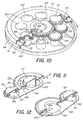
- Figures 8 to 12 illustrate yet another embodiment of a device according to the invention.
- it is a variant of the device shown in Figures 1 and 2, showing in particular similar control means and surfaces visible superior analogous in principle. That's why we will not repeat the description of these surfaces and data that they can wear.
- a base block of the device is formed of a base piece 103, serving as planet carrier thanks to a crown 104 with eight pivots projecting, and an upper plate 105 provided with feet 106 fixing it to base piece 103.
- This tray has a central hole circular 107 and a crown of eight circular holes 108 for the satellites.
- a peripheral gripping surface 109 is provided around the base part 103.
- An intermediate ring 110 is rotatably mounted on the base piece 103 and has a peripheral gripping surface 111.
- This ring has internal toothing 112 to eighty-two teeth.
- an upper ring 113 is rotatably mounted around the plate 105 and has a peripheral gripping surface 114. It is provided with a internal teeth 115 to eighty-four teeth.
- a first planetary gear is formed by the toothing 112 of the ring 110, a planetary idler gear 117 with teeth 116 to forty teeth, and a pinion gear 119 to twenty-one meshing teeth simultaneously on the teeth 112 and 116.
- a second gear planetary arranged in a plane slightly higher than that of the first, includes the toothing 115 of the upper ring 113, a idler planetary gear 123 with teeth 118 to thirty-eight teeth, which is mounted coaxially on the planetary pinion 117, and a satellite pinion 121 with twenty-three teeth meshing on the toothing 118 of the planetary pinion 123.
- the other satellites mesh only on one or the other of the planetary gears 117 and 123.
- Three satellites 124 to twenty-one teeth mesh with planetary gear 123, while that three satellites 125 to nineteen teeth mesh with the teeth 116 of the planetary gear 117.
- a rotation of the intermediate ring 110 (toothing 112) relative to the base block rotates the elements 119, 117 and 125
- a rotation of the upper ring 113 tilt 115 relative to the base block rotates the elements 121, 123 and 124. Consequently, the visible upper surfaces of said elements rotate by compared to others in a similar way to the example of Figures 1 and 2, except for the angular velocities because of the numbers of different teeth.
- a small ball 126 ( Figure 8) is trapped in the device and the game is to get it out through a hole 127 of the basic part 103, thanks to an appropriate positioning of the elements of the device.
- the ball 126 is trapped in a cylindrical housing 128 formed by an enlarged part of a groove annular 129 of the underside of the planetary pinion 123.
- This groove is closed downwards by the planetary pinion 117, having opposite annular groove 129 an annular groove 130 in which ball 126 can roll.
- the bottom of groove 130 has a circular hole 131 allowing the ball 126 to pass when it is exactly vertical to the housing 128.
- the planetary gear 117 constitutes a first shutter member between the housing 128 and the outlet hole 127. However, it is provided two more shutters above hole 127, under the form of two flat cams 132 and 133 actuated respectively by planet gears 119 and 121 and shown in more detail in Figures 11 and 12.
- the flat cam 132 has a hole oblong 134 whose width corresponds to the outside diameter of a lower cylindrical skirt 135 of the planetary gear 117, so that the cam 132 is guided in radial sliding on this skirt along the double arrow A.
- the other end of the cam 132 has a circular hole 136 fitted on a protuberance eccentric circular 137 of the satellite pinion 119, the rotation of which gives a connecting rod movement to the cam 132.
- the cam has a hole 138 for the passage of the ball 126. This hole not only moves radially along the double arrow A, but also in the circumferential direction along the double arrow B, i.e. only one position of the satellite pinion 119 makes the hole 138 of the cam coincide with the outlet hole 127.
- the second flat cam 133 is actuated in a similar manner, but by the satellite pinion 121.
- the planetary pinion 117 has been removed to clarify the drawing, but the cam is also guided by the skirt 135 of this pinion, thanks to a hole oblong 140.
- One end of the cam 133 has a circular hole 141 fitted on an eccentric circular protuberance 142 of the pinion 121.
- the other end of the cam has a hole 143 for the passage of the ball 126, this hole being moved radially along arrow C and tangentially along arrow D by the rotation of the satellite pinion 121.
- only one position of the satellite pinion 121 ensures coincidence between the hole 141 of the cam and the exit hole 127.
- the ball 126 can only be released in one unique position of elements 117, 119, 121 and 123 with respect to the base piece 103, so as to have an exact coincidence of the housing 128 of the ball with the holes 131, 138, 143 and 127.
- the ball can then fall by gravity through exit hole 127 and exit the device.
- it can be retained at the interior of hole 127 by a transparent plug (not shown) allowing to see for example the color of the ball.
- the game therefore consists in finding the position unique capable of releasing the ball, by appropriate rotations rings 110 and 113 on the base piece 103 in order to obtain the desired coincidences of visible top surfaces of elements rotary.
- These coincidences can be identified by scales graduated, indexes, complementary drawings etc., as we have described for the previous examples.
- the ball can be not only a sign of success clearance when released, but may additionally be of different colors indicating, for example, that the player is entitled to a prize more or less important in a lottery. This color is obviously not visible as long as the ball is inside his initial accommodation.
- the exit hole 127 can be sinuous for prevent seeing the ball in its housing. For example, a ball green can indicate the winning of a first prize, a yellow ball the winning a second prize and a red ball the right to a prize of consolation or a promotional item from a supplier whose mark constitutes a drawing to be reconstructed on the upper surface visible from the device.
- the device must be provided with a tamper-evident witness that no manipulation has been made on the device since its manufacturing.
- inviolability can be attested, for example by means of a tape glued to the peripheral surfaces 109, 111 and 114, this strip to be cut or torn to allow rotation of rings.
- We can also provide other witnesses such as tabs whose rupture is essential to allow the rotation of the rings.
- the device mainly comprises a witness, in the form of a metal ball 150 which, when the good combination is found, falls through a passage 151 (shown closed), in a housing 152 at the bottom of which is mounted a contactor 153.
- a contactor 153 When the ball closes the contact between two respectively positive and negative terminals of contactor 153, one battery 154 supplies an integrated circuit 155 arranged to control the emission either of a sound signal, or of a light signal, or of the two signals simultaneously.
- the described embodiments can undergo various modifications.
- the sound emitted corresponds to the illustrations of the device, for example the cry of the animal shown in the case of an educational game.
Landscapes
- Engineering & Computer Science (AREA)
- Multimedia (AREA)
- Toys (AREA)
- Pinball Game Machines (AREA)
- Details Of Cameras Including Film Mechanisms (AREA)
- Closed-Circuit Television Systems (AREA)
- Medicines Containing Antibodies Or Antigens For Use As Internal Diagnostic Agents (AREA)
- Measuring Pulse, Heart Rate, Blood Pressure Or Blood Flow (AREA)
Claims (19)
- Vorrichtung zum Spielen, mit der graphische oder alphanumerische Daten, die auf wenigstens einer oberen Fläche der Vorrichtung erscheinen, in Entsprechung gesetzt werden, mit:einem Basisblock (2, 50, 80, 103) mit einer ersten sichtbaren Oberfläche (6, 54, 81, 105) auf der oberen Fläche;wenigstens zwei Drehelementen (13, 17, 19, 21, 23, 60, 64, 71, 82-85, 113, 117, 119, 121, 123-125), die so angeordnet sind, daß sie sich am Basisblock um parallele Achsen drehen und eine zweite bzw. eine dritte Oberfläche besitzen, die auf der oberen Fläche sichtbar sind;wenigstens einem manuellen Antriebsmittel (10, 11, 13, 14, 60, 61, 90, 111, 114) zum Drehen wenigstens eines der Drehelemente in bezug auf den Basisblock;Rotationsübertragungsmitteln (12, 15, 18, 63, 66, 112, 115, 116, 118), die kinematische Verbindungen mit festen Beziehungen zwischen dem Basisblock, den Drehelementen und den manuellen Antriebsmitteln bilden;Winkelmarkierungsmitteln (41-46, 73-78), die an den sichtbaren Oberflächen des Basisblocks und der Drehelemente angeordnet sind und die Daten und die Ergebnisse in Form kreisförmiger Skalen, eines Zeigers und/oder anderer graphischer Elemente darstellen, wobei diese Markierungsmittel so angeordnet sind, daß sie durch Drehen der von den manuellen Mitteln angetriebenen Drehelemente in eine gegenseitige Entsprechung gebracht werden können, dadurch gekennzeichnet, daß zwei der Drehelemente (13, 17, 23, 60, 64, 113, 117, 123) koaxial sind und daß die Übertragungsmittel wenigstens ein Planetengetriebe aufweisen.
- Vorrichtung nach Anspruch 1, dadurch gekennzeichnet, daß die erste, die zweite und die dritte sichtbare Oberfläche paarweise benachbart sind, wobei sich eine von ihnen (25; 65) zwischen den beiden anderen (6, 24; 54, 62) befindet.
- Vorrichtung nach Anspruch 1 oder 2, dadurch gekennzeichnet, daß die Übertragungsmittel Getriebe enthalten.
- Vorrichtung nach Anspruch 1 oder 2, dadurch gekennzeichnet, daß die Übertragungsmittel Ketten oder Zahnriemen enthalten.
- Vorrichtung nach Anspruch 1, dadurch gekennzeichnet, daß die beiden Drehelemente (60, 64, 82-85) durch eine kinematische Verbindung mit festen Beziehungen miteinander und mit einem gemeinsamen manuellen Antriebsmittel (61, 90) gekoppelt sind.
- Vorrichtung nach Anspruch 1, dadurch gekennzeichnet, daß die beiden Drehmittel (17, 19; 21, 23; 119, 121) jeweils mit einem von zwei manuellen Antriebsmitteln (10, 13; 110, 113) gekoppelt sind, die unabhängig voneinander betätigt werden können.
- Vorrichtung nach Anspruch 1, dadurch gekennzeichnet, daß zu den beiden Drehelementen bzw. zum Basisblock (2) drei koaxiale Elemente des Planetengetriebes, nämlich zwei Planetenräder (13, 23, 113, 123) und ein Planetenradträger (4, 123), gehören.
- Vorrichtung nach Anspruch 1 oder 7, dadurch gekennzeichnet, daß die Planetenräder (19, 21) des Planetengetriebes ebenfalls Drehelemente bilden, die jeweils eine sichtbare Oberfläche (34, 35) besitzen, die mit Markierungsmitteln (44) versehen ist.
- Vorrichtung nach den Ansprüchen 1 und 7, dadurch gekennzeichnet, daß die Übertragungsmittel zwei koaxiale Planetengetriebe enthalten, die ein gemeinsames Element (4, 103) besitzen und jeweils mit einem der zwei manuellen Antriebsmittel (10, 13, 110, 113) gekoppelt sind.
- Vorrichtung nach Anspruch 9, dadurch gekennzeichnet, daß die manuellen Antriebsmittel äußere Planetenräder (10, 13, 110, 113) der Planetengetriebe sind und an ihrem Umfang Greifmittel (11, 14, 111, 114) aufweisen.
- Vorrichtung nach Anspruch 9, dadurch gekennzeichnet, daß das gemeinsame Element ein Planetenradträger (4) ist, der einen Teil des Basisblocks (2) bildet.
- Vorrichtung nach Anspruch 11, dadurch gekennzeichnet, daß der Planetenradträger (4) und zwei innere Planetenräder (17, 23) der Planetengetriebe auf der oberen Fläche (1) zueinander konzentrische, sichtbare Oberflächen (6, 24, 25) besitzen.
- Vorrichtung nach einem der vorangehenden Ansprüche, dadurch gekennzeichnet, daß sie einen verdeckten Aufnahmesitz (128) für einen Merker, insbesondere eine Kugel (126), eine Austritts- oder Anzeigeöffnung (127) für den Merker sowie bewegliche Verschlußorgane (117, 132, 133), die von den Drehelementen angetrieben werden und so beschaffen sind, daß sie einen Weg des Merkers zwischen dem Aufnahmesitz und der Öffnung verschließen, aufweist, wobei jedes Verschlußorgan ein Loch (131, 138, 143) für den Durchgang des Merkers (126) aufweist, wobei der Durchgang durch eine einzige Position einer gegenseitigen Übereinstimmung des Aufnahmesitzes, der Löcher und der Öffnung, die einer vorgegebenen Position der sichtbaren Flächen entspricht, freigegeben wird.
- Vorrichtung nach Anspruch 13, dadurch gekennzeichnet, daß sich der Aufnahmesitz (128) in einem (123) der Drehelemente befindet.
- Vorrichtung nach Anspruch 13 oder 14, dadurch gekennzeichnet, daß wenigstens eines der Verschlußelemente durch eines (117) der Drehelemente gebildet ist.
- Vorrichtung nach einem der Ansprüche 13 bis 15, dadurch gekennzeichnet, daß wenigstens eines der Verschlußelemente eine Nockenplatte (132, 133) ist, die durch eines (119, 121) der Drehelemente zu einer Verschiebungsbewegung (A, C) und einer Schwenkbewegung (B, D) angetrieben wird.
- Vorrichtung nach Anspruch 13, dadurch gekennzeichnet, daß der Merker (126) ein Gewinnangabekennzeichen, insbesondere eine bestimmte Farbe, aufweist.
- Vorrichtung nach Anspruch 13, dadurch gekennzeichnet, daß sie Mittel enthält, die mit dem Merker zusammenwirken, um zum Zeitpunkt der Freigabe dieses Merkers ein akustisches und/oder visuelles Signal auszulösen.
- Vorrichtung nach Anspruch 18, dadurch gekennzeichnet, daß die Mittel einen Ein/Aus-Schalter (153), der durch den Merker betätigt werden kann, eine Energiequelle (154) und eine integrierte elektronische Schaltung, die das akustische und/oder visuelle Signal aussenden kann, aufweisen.
Applications Claiming Priority (3)
| Application Number | Priority Date | Filing Date | Title |
|---|---|---|---|
| FR9409064 | 1994-07-15 | ||
| FR9409064A FR2722423B1 (fr) | 1994-07-15 | 1994-07-15 | Dispositif a but ludique pour mettre en correspondance des donnees ou des dessins |
| PCT/CH1995/000159 WO1996002307A1 (fr) | 1994-07-15 | 1995-07-07 | Dispositif a but ludique pour mettre en correspondance des donnees ou des dessins |
Publications (2)
| Publication Number | Publication Date |
|---|---|
| EP0723471A1 EP0723471A1 (de) | 1996-07-31 |
| EP0723471B1 true EP0723471B1 (de) | 1999-12-08 |
Family
ID=9465630
Family Applications (1)
| Application Number | Title | Priority Date | Filing Date |
|---|---|---|---|
| EP95923166A Expired - Lifetime EP0723471B1 (de) | 1994-07-15 | 1995-07-07 | Spielvorrichtung zum abbilden von daten oder zeichnungen |
Country Status (11)
| Country | Link |
|---|---|
| US (1) | US5634641A (de) |
| EP (1) | EP0723471B1 (de) |
| JP (1) | JPH09509088A (de) |
| AT (1) | ATE187349T1 (de) |
| AU (1) | AU674818B2 (de) |
| CA (1) | CA2171628A1 (de) |
| DE (1) | DE69513794T2 (de) |
| ES (1) | ES2140686T3 (de) |
| FR (1) | FR2722423B1 (de) |
| NZ (1) | NZ288562A (de) |
| WO (1) | WO1996002307A1 (de) |
Families Citing this family (9)
| Publication number | Priority date | Publication date | Assignee | Title |
|---|---|---|---|---|
| DE19737499C1 (de) * | 1997-08-28 | 1998-07-30 | Muharem Durakovic | Dreidimensionales logisches Spielzeug |
| US6460849B1 (en) * | 1999-03-16 | 2002-10-08 | Jeffrey W. Bean | Rotating ring game |
| WO2001017630A2 (en) | 1999-09-09 | 2001-03-15 | Dsle System S.A. | Magnetically animated doll |
| CN102039046B (zh) * | 2009-10-21 | 2012-12-05 | 高圣荣 | 智力转盘 |
| GB2478319B (en) * | 2010-03-03 | 2013-07-17 | Michael Philip Paget | An amusement device |
| USD791244S1 (en) * | 2015-05-28 | 2017-07-04 | Fikst, Llc | Gift card gear puzzle |
| US10589167B2 (en) | 2017-03-08 | 2020-03-17 | Wowwee Group Ltd. | Rotating ball-in-a-maze puzzle game |
| CN111300391B (zh) * | 2020-03-31 | 2022-02-18 | 杭州中含创新科技有限公司 | 一种积木式机器人的旋转动力模块 |
| US20230052118A1 (en) * | 2021-08-13 | 2023-02-16 | Leonid Shafir | Manipulative puzzle maze |
Family Cites Families (6)
| Publication number | Priority date | Publication date | Assignee | Title |
|---|---|---|---|---|
| US4560164A (en) * | 1984-06-13 | 1985-12-24 | Darling Phillip H | Toy puzzle |
| US4752074A (en) * | 1986-10-02 | 1988-06-21 | Juang Shih Hung | Puzzle game |
| GB2213739A (en) * | 1987-12-23 | 1989-08-23 | Wiggs C C | Logical puzzle |
| US4784387A (en) * | 1988-02-01 | 1988-11-15 | Liversidge Thomas K | Game |
| CA2020225A1 (en) * | 1990-06-29 | 1991-12-30 | Antonio Cannata | Puzzle |
| IL101130A0 (en) * | 1991-03-05 | 1992-11-15 | Gerhard Huncaga | Puzzle |
-
1994
- 1994-07-15 FR FR9409064A patent/FR2722423B1/fr not_active Expired - Fee Related
-
1995
- 1995-07-07 AU AU27839/95A patent/AU674818B2/en not_active Ceased
- 1995-07-07 WO PCT/CH1995/000159 patent/WO1996002307A1/fr not_active Ceased
- 1995-07-07 CA CA002171628A patent/CA2171628A1/fr not_active Abandoned
- 1995-07-07 EP EP95923166A patent/EP0723471B1/de not_active Expired - Lifetime
- 1995-07-07 US US08/612,868 patent/US5634641A/en not_active Expired - Fee Related
- 1995-07-07 DE DE69513794T patent/DE69513794T2/de not_active Expired - Fee Related
- 1995-07-07 JP JP8504553A patent/JPH09509088A/ja not_active Withdrawn
- 1995-07-07 NZ NZ288562A patent/NZ288562A/en unknown
- 1995-07-07 AT AT95923166T patent/ATE187349T1/de not_active IP Right Cessation
- 1995-07-07 ES ES95923166T patent/ES2140686T3/es not_active Expired - Lifetime
Also Published As
| Publication number | Publication date |
|---|---|
| EP0723471A1 (de) | 1996-07-31 |
| WO1996002307A1 (fr) | 1996-02-01 |
| AU674818B2 (en) | 1997-01-09 |
| ATE187349T1 (de) | 1999-12-15 |
| CA2171628A1 (fr) | 1996-02-01 |
| DE69513794D1 (de) | 2000-01-13 |
| US5634641A (en) | 1997-06-03 |
| JPH09509088A (ja) | 1997-09-16 |
| FR2722423B1 (fr) | 1996-09-27 |
| NZ288562A (en) | 1997-05-26 |
| FR2722423A1 (fr) | 1996-01-19 |
| ES2140686T3 (es) | 2000-03-01 |
| AU2783995A (en) | 1996-02-16 |
| DE69513794T2 (de) | 2000-04-20 |
Similar Documents
| Publication | Publication Date | Title |
|---|---|---|
| EP0723471B1 (de) | Spielvorrichtung zum abbilden von daten oder zeichnungen | |
| EP0756217B1 (de) | Jährlicher Kalendermechanismus für Uhren | |
| FR2458860A1 (fr) | Dispositif d'affichage pour une machine dans laquelle on doit afficher une information | |
| CH699134B1 (fr) | Pièce d'horlogerie munie d'un tour d'heures variable. | |
| EP1475679A1 (de) | Verfahren zum Anzeigen der Mondphasen, insbesondere in einem Uhrwerk | |
| WO1991011756A1 (fr) | Dispositif de representation de la lune, notamment sur le cadran d'une montre | |
| FR2519559A1 (de) | ||
| EP1607807B1 (de) | Uhr mit ästhetischen Sondereffekten | |
| EP0329553B1 (de) | Analogzeitgebende Vorrichtung | |
| EP1784691A1 (de) | Mechanismus zum anzeigen von auf dem ziffernblatt einer uhr produzierten zahlen oder zeichen | |
| EP1784692B1 (de) | Mechanismus zum anzeigen von bildern, zahlen oder zeichen, die auf dem zifferblatt einer uhr produziert werden | |
| WO1991000554A1 (fr) | Dispositif de presentation d'informations par effets optiques notamment pour appareils de mesure | |
| FR2741967A1 (fr) | Pendule" mysterieuse" dite giratoire | |
| CH705722B1 (fr) | Pièce d'horlogerie. | |
| FR2657710A1 (fr) | Globe-horloge. | |
| FR2497463A1 (de) | ||
| FR2563645A1 (fr) | Instrument pour l'obtention et la saisie de donnees aleatoires | |
| EP3242166A1 (de) | Mechanismus zur auslösung einer animation | |
| FR2462918A1 (fr) | Jeu de societe | |
| EP2821861B1 (de) | Uhr, die mit einer Animation in Form einer Blume ausgestattet ist | |
| EP4264379B1 (de) | Mechanisches uhrwerk mit einer informationsanzeigevorrichtung | |
| FR2507490A1 (fr) | Jeu du genre " casse-tete " comportant des faces reconnaissables au toucher | |
| CH709374A1 (fr) | Dispositif pour produire un effet optique notamment pour pièce d'horlogerie. | |
| EP1475680A1 (de) | Verfahren zum Anzeigen der Mondphasen, insbesondere in einem Uhrwerk | |
| BE422951A (de) |
Legal Events
| Date | Code | Title | Description |
|---|---|---|---|
| PUAI | Public reference made under article 153(3) epc to a published international application that has entered the european phase |
Free format text: ORIGINAL CODE: 0009012 |
|
| 17P | Request for examination filed |
Effective date: 19960409 |
|
| AK | Designated contracting states |
Kind code of ref document: A1 Designated state(s): AT BE CH DE DK ES FR GB GR IE IT LI LU MC NL PT SE |
|
| 17Q | First examination report despatched |
Effective date: 19980401 |
|
| GRAG | Despatch of communication of intention to grant |
Free format text: ORIGINAL CODE: EPIDOS AGRA |
|
| GRAG | Despatch of communication of intention to grant |
Free format text: ORIGINAL CODE: EPIDOS AGRA |
|
| GRAH | Despatch of communication of intention to grant a patent |
Free format text: ORIGINAL CODE: EPIDOS IGRA |
|
| GRAH | Despatch of communication of intention to grant a patent |
Free format text: ORIGINAL CODE: EPIDOS IGRA |
|
| ITF | It: translation for a ep patent filed | ||
| GRAA | (expected) grant |
Free format text: ORIGINAL CODE: 0009210 |
|
| RAP3 | Party data changed (applicant data changed or rights of an application transferred) |
Owner name: DSLE SYSTEM S.A. |
|
| AK | Designated contracting states |
Kind code of ref document: B1 Designated state(s): AT BE CH DE DK ES FR GB GR IE IT LI LU MC NL PT SE |
|
| PG25 | Lapsed in a contracting state [announced via postgrant information from national office to epo] |
Ref country code: SE Free format text: THE PATENT HAS BEEN ANNULLED BY A DECISION OF A NATIONAL AUTHORITY Effective date: 19991208 Ref country code: NL Free format text: LAPSE BECAUSE OF FAILURE TO SUBMIT A TRANSLATION OF THE DESCRIPTION OR TO PAY THE FEE WITHIN THE PRESCRIBED TIME-LIMIT Effective date: 19991208 Ref country code: GR Free format text: LAPSE BECAUSE OF NON-PAYMENT OF DUE FEES Effective date: 19991208 Ref country code: AT Free format text: LAPSE BECAUSE OF FAILURE TO SUBMIT A TRANSLATION OF THE DESCRIPTION OR TO PAY THE FEE WITHIN THE PRESCRIBED TIME-LIMIT Effective date: 19991208 |
|
| REF | Corresponds to: |
Ref document number: 187349 Country of ref document: AT Date of ref document: 19991215 Kind code of ref document: T |
|
| REG | Reference to a national code |
Ref country code: CH Ref legal event code: EP |
|
| GBT | Gb: translation of ep patent filed (gb section 77(6)(a)/1977) |
Effective date: 19991208 |
|
| REF | Corresponds to: |
Ref document number: 69513794 Country of ref document: DE Date of ref document: 20000113 |
|
| REG | Reference to a national code |
Ref country code: IE Ref legal event code: FG4D |
|
| REG | Reference to a national code |
Ref country code: ES Ref legal event code: FG2A Ref document number: 2140686 Country of ref document: ES Kind code of ref document: T3 |
|
| PG25 | Lapsed in a contracting state [announced via postgrant information from national office to epo] |
Ref country code: DK Free format text: LAPSE BECAUSE OF FAILURE TO SUBMIT A TRANSLATION OF THE DESCRIPTION OR TO PAY THE FEE WITHIN THE PRESCRIBED TIME-LIMIT Effective date: 20000308 |
|
| PG25 | Lapsed in a contracting state [announced via postgrant information from national office to epo] |
Ref country code: PT Free format text: LAPSE BECAUSE OF FAILURE TO SUBMIT A TRANSLATION OF THE DESCRIPTION OR TO PAY THE FEE WITHIN THE PRESCRIBED TIME-LIMIT Effective date: 20000309 |
|
| NLV1 | Nl: lapsed or annulled due to failure to fulfill the requirements of art. 29p and 29m of the patents act | ||
| PG25 | Lapsed in a contracting state [announced via postgrant information from national office to epo] |
Ref country code: LU Free format text: LAPSE BECAUSE OF NON-PAYMENT OF DUE FEES Effective date: 20000707 |
|
| PGFP | Annual fee paid to national office [announced via postgrant information from national office to epo] |
Ref country code: CH Payment date: 20000711 Year of fee payment: 6 |
|
| PG25 | Lapsed in a contracting state [announced via postgrant information from national office to epo] |
Ref country code: MC Free format text: THE PATENT HAS BEEN ANNULLED BY A DECISION OF A NATIONAL AUTHORITY Effective date: 20000731 Ref country code: BE Free format text: LAPSE BECAUSE OF NON-PAYMENT OF DUE FEES Effective date: 20000731 |
|
| PLBE | No opposition filed within time limit |
Free format text: ORIGINAL CODE: 0009261 |
|
| STAA | Information on the status of an ep patent application or granted ep patent |
Free format text: STATUS: NO OPPOSITION FILED WITHIN TIME LIMIT |
|
| PG25 | Lapsed in a contracting state [announced via postgrant information from national office to epo] |
Ref country code: IE Free format text: LAPSE BECAUSE OF NON-PAYMENT OF DUE FEES Effective date: 20001116 |
|
| 26N | No opposition filed | ||
| REG | Reference to a national code |
Ref country code: IE Ref legal event code: FD4D |
|
| BERE | Be: lapsed |
Owner name: S.A. DSLE SYSTEM Effective date: 20000731 |
|
| PG25 | Lapsed in a contracting state [announced via postgrant information from national office to epo] |
Ref country code: LI Free format text: LAPSE BECAUSE OF NON-PAYMENT OF DUE FEES Effective date: 20010731 Ref country code: CH Free format text: LAPSE BECAUSE OF NON-PAYMENT OF DUE FEES Effective date: 20010731 |
|
| REG | Reference to a national code |
Ref country code: GB Ref legal event code: IF02 |
|
| REG | Reference to a national code |
Ref country code: CH Ref legal event code: PL |
|
| PGFP | Annual fee paid to national office [announced via postgrant information from national office to epo] |
Ref country code: GB Payment date: 20030702 Year of fee payment: 9 |
|
| PGFP | Annual fee paid to national office [announced via postgrant information from national office to epo] |
Ref country code: FR Payment date: 20030731 Year of fee payment: 9 Ref country code: ES Payment date: 20030731 Year of fee payment: 9 |
|
| PGFP | Annual fee paid to national office [announced via postgrant information from national office to epo] |
Ref country code: DE Payment date: 20030811 Year of fee payment: 9 |
|
| PG25 | Lapsed in a contracting state [announced via postgrant information from national office to epo] |
Ref country code: GB Free format text: LAPSE BECAUSE OF NON-PAYMENT OF DUE FEES Effective date: 20040707 |
|
| PG25 | Lapsed in a contracting state [announced via postgrant information from national office to epo] |
Ref country code: ES Free format text: LAPSE BECAUSE OF NON-PAYMENT OF DUE FEES Effective date: 20040708 |
|
| PG25 | Lapsed in a contracting state [announced via postgrant information from national office to epo] |
Ref country code: DE Free format text: LAPSE BECAUSE OF NON-PAYMENT OF DUE FEES Effective date: 20050201 |
|
| GBPC | Gb: european patent ceased through non-payment of renewal fee |
Effective date: 20040707 |
|
| PG25 | Lapsed in a contracting state [announced via postgrant information from national office to epo] |
Ref country code: FR Free format text: LAPSE BECAUSE OF NON-PAYMENT OF DUE FEES Effective date: 20050331 |
|
| REG | Reference to a national code |
Ref country code: FR Ref legal event code: ST |
|
| PG25 | Lapsed in a contracting state [announced via postgrant information from national office to epo] |
Ref country code: IT Free format text: LAPSE BECAUSE OF NON-PAYMENT OF DUE FEES Effective date: 20050707 |
|
| REG | Reference to a national code |
Ref country code: ES Ref legal event code: FD2A Effective date: 20040708 |