EP0723785B1 - Méthode et dispositif de détermination de la fonction de transfert d'un système de connexion pour appareil d'assistance respiratoire - Google Patents
Méthode et dispositif de détermination de la fonction de transfert d'un système de connexion pour appareil d'assistance respiratoire Download PDFInfo
- Publication number
- EP0723785B1 EP0723785B1 EP95119588A EP95119588A EP0723785B1 EP 0723785 B1 EP0723785 B1 EP 0723785B1 EP 95119588 A EP95119588 A EP 95119588A EP 95119588 A EP95119588 A EP 95119588A EP 0723785 B1 EP0723785 B1 EP 0723785B1
- Authority
- EP
- European Patent Office
- Prior art keywords
- unit
- gas
- gas flow
- flow pattern
- ventilator
- Prior art date
- Legal status (The legal status is an assumption and is not a legal conclusion. Google has not performed a legal analysis and makes no representation as to the accuracy of the status listed.)
- Expired - Lifetime
Links
- 238000012546 transfer Methods 0.000 title claims description 54
- 238000000034 method Methods 0.000 title claims description 15
- 238000005259 measurement Methods 0.000 claims description 42
- 238000012360 testing method Methods 0.000 claims description 40
- 210000002345 respiratory system Anatomy 0.000 claims description 39
- 230000029058 respiratory gaseous exchange Effects 0.000 claims description 35
- 210000004072 lung Anatomy 0.000 claims description 34
- 230000003434 inspiratory effect Effects 0.000 claims description 22
- 230000033228 biological regulation Effects 0.000 claims description 5
- 238000001228 spectrum Methods 0.000 claims description 4
- 238000009423 ventilation Methods 0.000 claims description 2
- 239000007789 gas Substances 0.000 description 131
- 238000004364 calculation method Methods 0.000 description 8
- 230000001105 regulatory effect Effects 0.000 description 5
- 238000010586 diagram Methods 0.000 description 3
- 230000001580 bacterial effect Effects 0.000 description 2
- 230000001276 controlling effect Effects 0.000 description 2
- 238000011161 development Methods 0.000 description 2
- 230000010354 integration Effects 0.000 description 2
- 239000011159 matrix material Substances 0.000 description 2
- 230000003321 amplification Effects 0.000 description 1
- QVGXLLKOCUKJST-UHFFFAOYSA-N atomic oxygen Chemical compound [O] QVGXLLKOCUKJST-UHFFFAOYSA-N 0.000 description 1
- 230000015572 biosynthetic process Effects 0.000 description 1
- 239000003990 capacitor Substances 0.000 description 1
- 239000003795 chemical substances by application Substances 0.000 description 1
- 230000006835 compression Effects 0.000 description 1
- 238000007906 compression Methods 0.000 description 1
- 238000009833 condensation Methods 0.000 description 1
- 230000005494 condensation Effects 0.000 description 1
- 238000011109 contamination Methods 0.000 description 1
- 230000007423 decrease Effects 0.000 description 1
- 230000003111 delayed effect Effects 0.000 description 1
- 238000009795 derivation Methods 0.000 description 1
- 238000003745 diagnosis Methods 0.000 description 1
- 208000037265 diseases, disorders, signs and symptoms Diseases 0.000 description 1
- 208000035475 disorder Diseases 0.000 description 1
- 238000006073 displacement reaction Methods 0.000 description 1
- 238000001035 drying Methods 0.000 description 1
- 238000001914 filtration Methods 0.000 description 1
- 238000013178 mathematical model Methods 0.000 description 1
- 238000002156 mixing Methods 0.000 description 1
- 238000003199 nucleic acid amplification method Methods 0.000 description 1
- 239000001301 oxygen Substances 0.000 description 1
- 229910052760 oxygen Inorganic materials 0.000 description 1
- 238000012545 processing Methods 0.000 description 1
Images


Classifications
-
- G—PHYSICS
- G05—CONTROLLING; REGULATING
- G05B—CONTROL OR REGULATING SYSTEMS IN GENERAL; FUNCTIONAL ELEMENTS OF SUCH SYSTEMS; MONITORING OR TESTING ARRANGEMENTS FOR SUCH SYSTEMS OR ELEMENTS
- G05B17/00—Systems involving the use of models or simulators of said systems
- G05B17/02—Systems involving the use of models or simulators of said systems electric
-
- A—HUMAN NECESSITIES
- A61—MEDICAL OR VETERINARY SCIENCE; HYGIENE
- A61M—DEVICES FOR INTRODUCING MEDIA INTO, OR ONTO, THE BODY; DEVICES FOR TRANSDUCING BODY MEDIA OR FOR TAKING MEDIA FROM THE BODY; DEVICES FOR PRODUCING OR ENDING SLEEP OR STUPOR
- A61M16/00—Devices for influencing the respiratory system of patients by gas treatment, e.g. ventilators; Tracheal tubes
- A61M16/021—Devices for influencing the respiratory system of patients by gas treatment, e.g. ventilators; Tracheal tubes operated by electrical means
- A61M16/022—Control means therefor
- A61M16/024—Control means therefor including calculation means, e.g. using a processor
-
- A—HUMAN NECESSITIES
- A61—MEDICAL OR VETERINARY SCIENCE; HYGIENE
- A61M—DEVICES FOR INTRODUCING MEDIA INTO, OR ONTO, THE BODY; DEVICES FOR TRANSDUCING BODY MEDIA OR FOR TAKING MEDIA FROM THE BODY; DEVICES FOR PRODUCING OR ENDING SLEEP OR STUPOR
- A61M16/00—Devices for influencing the respiratory system of patients by gas treatment, e.g. ventilators; Tracheal tubes
- A61M16/10—Preparation of respiratory gases or vapours
- A61M16/105—Filters
- A61M16/1055—Filters bacterial
-
- A—HUMAN NECESSITIES
- A61—MEDICAL OR VETERINARY SCIENCE; HYGIENE
- A61M—DEVICES FOR INTRODUCING MEDIA INTO, OR ONTO, THE BODY; DEVICES FOR TRANSDUCING BODY MEDIA OR FOR TAKING MEDIA FROM THE BODY; DEVICES FOR PRODUCING OR ENDING SLEEP OR STUPOR
- A61M16/00—Devices for influencing the respiratory system of patients by gas treatment, e.g. ventilators; Tracheal tubes
- A61M16/10—Preparation of respiratory gases or vapours
- A61M16/105—Filters
- A61M16/106—Filters in a path
- A61M16/1065—Filters in a path in the expiratory path
-
- A—HUMAN NECESSITIES
- A61—MEDICAL OR VETERINARY SCIENCE; HYGIENE
- A61M—DEVICES FOR INTRODUCING MEDIA INTO, OR ONTO, THE BODY; DEVICES FOR TRANSDUCING BODY MEDIA OR FOR TAKING MEDIA FROM THE BODY; DEVICES FOR PRODUCING OR ENDING SLEEP OR STUPOR
- A61M16/00—Devices for influencing the respiratory system of patients by gas treatment, e.g. ventilators; Tracheal tubes
- A61M16/0003—Accessories therefor, e.g. sensors, vibrators, negative pressure
- A61M2016/003—Accessories therefor, e.g. sensors, vibrators, negative pressure with a flowmeter
- A61M2016/0033—Accessories therefor, e.g. sensors, vibrators, negative pressure with a flowmeter electrical
- A61M2016/0039—Accessories therefor, e.g. sensors, vibrators, negative pressure with a flowmeter electrical in the inspiratory circuit
-
- A—HUMAN NECESSITIES
- A61—MEDICAL OR VETERINARY SCIENCE; HYGIENE
- A61M—DEVICES FOR INTRODUCING MEDIA INTO, OR ONTO, THE BODY; DEVICES FOR TRANSDUCING BODY MEDIA OR FOR TAKING MEDIA FROM THE BODY; DEVICES FOR PRODUCING OR ENDING SLEEP OR STUPOR
- A61M16/00—Devices for influencing the respiratory system of patients by gas treatment, e.g. ventilators; Tracheal tubes
- A61M16/0003—Accessories therefor, e.g. sensors, vibrators, negative pressure
- A61M2016/003—Accessories therefor, e.g. sensors, vibrators, negative pressure with a flowmeter
- A61M2016/0033—Accessories therefor, e.g. sensors, vibrators, negative pressure with a flowmeter electrical
- A61M2016/0042—Accessories therefor, e.g. sensors, vibrators, negative pressure with a flowmeter electrical in the expiratory circuit
-
- A—HUMAN NECESSITIES
- A61—MEDICAL OR VETERINARY SCIENCE; HYGIENE
- A61M—DEVICES FOR INTRODUCING MEDIA INTO, OR ONTO, THE BODY; DEVICES FOR TRANSDUCING BODY MEDIA OR FOR TAKING MEDIA FROM THE BODY; DEVICES FOR PRODUCING OR ENDING SLEEP OR STUPOR
- A61M2205/00—General characteristics of the apparatus
- A61M2205/70—General characteristics of the apparatus with testing or calibration facilities
-
- A—HUMAN NECESSITIES
- A61—MEDICAL OR VETERINARY SCIENCE; HYGIENE
- A61M—DEVICES FOR INTRODUCING MEDIA INTO, OR ONTO, THE BODY; DEVICES FOR TRANSDUCING BODY MEDIA OR FOR TAKING MEDIA FROM THE BODY; DEVICES FOR PRODUCING OR ENDING SLEEP OR STUPOR
- A61M2230/00—Measuring parameters of the user
- A61M2230/40—Respiratory characteristics
- A61M2230/46—Resistance or compliance of the lungs
Definitions
- the present invention relates to a method for at least determining a transfer function for a connection system in a ventilator system, comprising a ventilator unit at least in respect to the parameters pressure and flow.
- the transfer function designates the way in which the connection system influences the predetermined gas flow pattern and can be used to compensate regulation of the pressure and flow of the breathing gas.
- ventilator systems respirator systems
- today's ventilator systems can be controlled to supply a breathing gas to a patient according to a plurality of different operating modes, a physician then being able to select the operating mode deemed most suitable for the patient.
- gas flow pattern refers to pressure and flow characteristics over time. So pressure and flow in any given gas flow pattern can display predefined variations over time. But even if the regulatory system is capable of delivering a gas flow which corresponds almost exactly to a target gas flow pattern, it is not certain that the gas flow received by the patient has the target gas flow pattern. This is because the interjacent connection system influences the gas flow's gas flow pattern.
- the connection system can e.g.
- connection system comprises tubes, humidifiers, dehumidifiers, bacterial filters etc.
- Flow resistance in gas lines and other components in the connection system influences gas flow in one way.
- the total volume taken up by the connection system influences gas flow in another way. This is because gases are highly compressible.
- the influence to which gas flow is subjected in the connection system changes the pattern of gas flow in respect to delay and morphology (morphology here referring to variations in pressure and flow over time).
- an Operating Manual for the aforementioned Servo Ventilator 300, AG 0593 3.5, Siemens-Elema AB, 1993, pp. 94-98 describes compensation for the connection system's compressible volume. Compensation means that the physician must e.g. set a larger minute volume for the breathing gas to be supplied to the patient to ensure delivery to the patient of the target minute volume. Here, the physician is forced to make the calculations required to achieve the necessary compensation.
- the calculation example on page 98 in the manual for an adult patient shows that minute volume had to be increased by 2.5 1 per minute when the target minute volume was 7.5 1 per minute. Compensation naturally varies from case to case. The need for compensation depends in particular on the connection system's configuration. However, the calculation example does provide an indication of the compensation needed for minute volume.
- connection system's compressible volume e.g. the Puritan-Bennett, 7200 series Microprocessor Ventilator, Option 30/40, Part Number 20522A, March 1986.
- gas flow pattern refers to pressure and flow variation over time. If the flowing gas is viewed as a gas pillar passing through the connection system, it will be realized that even simple compression of the gas pillar changes the pillar's flanks and, in particular, its pressure and flow variations. So compressible volume does not indicate anything about e.g. the way in which a target pressure increase flank for the gas pillar is influenced on its way to the patient's respiratory system. Determining compensation for the connection system's compressible volume does not therefore supply sufficient information for use in calculating compensation of the gas flow pattern. As already noted, the flow of gas is also delayed in the connection system.
- determining the lungs' various mechanical parameters is desirable. Determination of resistance and compliance is especially important. Roughly speaking, compliance can be determined in ways similar to determinations of compressible volume in the connection system of the known ventilator systems. However, one problem is that the connection system's influence on gas flow is not fully known, so determination of the lungs' mechanical parameters is uncertain. Moreover, the properties of these mechanical parameters can also influence the gas flow's gas flow pattern.
- One object of the invention is to set forth a method for more accurate determination of a transfer function for a connection system between a ventilator unit and a respiratory system.
- Another object of the invention is to set forth a method for determining, with greater accuracy than hitherto, the influence of the respiratory system on the flow pattern of a gas.
- Yet another object of the invention is to set forth an apparatus which can be connected to a respiratory system in order to supply and remove breathing gas according to a specific gas flow pattern and which can compensate for the interjacent connection system's influence on the gas flow pattern.
- a method for determining the transfer function is obtained in accordance with the invention by the following methodological steps: connection of the connection system to the ventilator unit; supply of a gas with a first test gas flow pattern from a gas-regulating unit in the ventilator unit, measurement in a measurement unit of an ensuing response gas flow pattern for the gas; and determination of the transfer function from the test gas flow pattern and the response gas flow pattern.
- this procedure resembles determination of the transfer function for unknown systems in electronics (e.g. automatic control).
- gases have very specific properties which are hard to establish, as regards flow and compressibility.
- regulation of a gas flow with sufficient accuracy to permit reliable determination of what the gas flow pattern should look like has hitherto been impossible in the ventilator art.
- earlier systems have not been able to achieve this with rapidity and accuracy sufficient to ensure that the emitted gas flow really possesses the desired gas flow pattern.
- Mathematical determination of the transfer function can be performed in a plurality of known manners.
- One possibility is to use the flow and pressure of the gas fed to the connection system as input signals for the connection system and to use the flow and pressure of gas having passed through the entire connection system as output signals for the connection system.
- all these flows and pressures can be used as input signals for the connection system, and flow and pressure are measured at the part of the connection system, which is to be connected to the respiratory system, and used as output signals.
- a mathematical model structure e.g. a Box-Jenkins model structure, is then used and adapted to the measurement values.
- the Box-Jenkins model is well-known and described in the automatic control literature, e.g. in " Modellbygge och simulering" by L. Ljung and T. Glad (p, 234), Studentlitteratur Lund, 1991 .
- the above model is described in the one-dimensional case in the said book, whereas it has been generalized into multiple dimensions for application to the model according to the invention, i.e. the above model is a matrix equation.
- the lung model suitably contains a flow meter and pressure meter for generating the connection system's output signals.
- An improvement of the method is achieved in accordance with the invention by the following additional methodological steps after connection of the connection system to the respiratory system: supply of a gas with a second test gas flow pattern from the gas-regulating unit in the ventilator unit; measurement in the measurement unit of an ensuing second response gas flow pattern for the gas; and determination of the respiratory system's influence on the gas' flow pattern from the second test gas flow pattern, the second response gas flow pattern and the determined transfer function.
- connection system and the respiratory system are regarded as two interconnected systems, the characteristics of the respiratory system and its influence on a gas flow's gas flow pattern can be determined when the way the connection system influences the gas flow pattern is taken into account. This influence is known from determination of the transfer function, so the influence of the respiratory system can be determined more accurately than has hitherto been possible. In principle, the same test gas flow pattern can be used for determining both the transfer function and the influence of the respiratory system.
- test gas flow pattern displayed a frequency spectrum corresponding to the different frequency spectra present in the ventilation modes in which the ventilator unit is capable of operating.
- the transfer function were determined from a number of pre-programmed model structures, preferably both linear and non-linear, all model structures being adapted to the measurement values and the model structure displaying the highest correlation is selected as the transfer function.
- An apparatus for performing the method is achieved in accordance with the invention in that an apparatus comprising a ventilator unit and a connection system, connected to the ventilator unit and connectable to the respiratory system, said ventilator unit comprising a gas-regulating unit, comprising at least one flow meter and a pressure meter in an inspiratory section of the ventilator unit, in order to generate a breathing gas flow with a specific gas flow pattern, and a measurement unit, comprising a flow meter and a pressure meter in an expiratory section of the ventilator unit, for measuring the gas parameters pressure and flow, which is characterized by a compensation unit, connected to the measurement unit and the gas-regulating unit, said compensation being adapted to determine the connection system's transfer function based on the specific gas flow pattern generated by the gas regulating unit and pressure and flow as measured by the measurement unit.
- the compensation unit is devised to determine the transfer function from the use of measurement signals from the meters in the inspiratory section as the connection system's input signals and measurement signals from the meters in the expiratory section as output signals. This corresponds to the first case described above.
- the apparatus further comprised a diagnostic unit connected to the measurement unit and the compensation unit in order to determine at least one mechanical lung parameter related to the living creature's respiratory system. It would be particularly advantageous if the diagnostic unit could determine one or both of the mechanical lung parameters resistance and compliance.
- the measurement unit further comprises a test lung, connectable to the connection system, a flow meter and/or pressure meter being arranged in said test lung to measure flow and/or pressure
- the compensation unit determines the transfer function from the use of measurement signals from the meters in the inspiratory section and expiratory section as the connection system's input signals and measurement signals from the meters in the test lung as output signals. This corresponds to the second case described above. It should be noted that sufficient information can be obtained by only studying the transfer function with respect to flow or pressure.
- the test lung can advantageously be integrated into the ventilator unit.
- the compensation unit were devised to calculate a compensation factor, which can be sent to the gas-regulating unit, changing its emission of breathing gas with the determined gas flow pattern so the breathing system receives a breathing gas flow essentially in accordance with the determined gas flow pattern.
- a compensation factor which can be sent to the gas-regulating unit, changing its emission of breathing gas with the determined gas flow pattern so the breathing system receives a breathing gas flow essentially in accordance with the determined gas flow pattern.
- the ventilator system 2 shown in FIG. 1 comprises a ventilator unit 4 and a connection system 6 and is connected to the respiratory system 8 of a living creature.
- the ventilator unit 4 and the connection system 6 constitute the apparatus set forth in patent claims 6 to 9.
- the respiratory system 8 is supplied with a breathing gas, via the connection system 6, from the ventilator unit 4. Gas expired from the respiratory system 8 is returned to the ventilator unit 4 via the connection system 6.
- the ventilator unit 4 can consist of a modified Servo Ventilator 300, Siemens-Elema AB, Solna, Sweden.
- the ventilator unit 4 has a inspiratory section and an expiratory section.
- Three gas connections 10A, 10B, 10C are arranged by the inspiratory section. Up to three gas sources can be connected to them for supplying gases to the ventilator unit 4.
- existing, high-pressure piped air and oxygen supplies in hospitals can be connected to the gas connections 10A, 10B, 10C.
- mobile pressurized gas cylinders or bottles can be used.
- a first flow meter 12A, a second flow meter 12B and a third flow meter 12C are arranged in the ventilator unit's 4 inspiratory section at each gas connection 10A, 10B, 10C to measure the flow of a passing gas.
- a first inspiratory valve 14A, a second inspiratory valve 14B and a third inspiratory valve 14C are also arranged by each gas connection 10A, 10B, 10C to regulate a flow of passing gas.
- the supplied gases are mixed in a mixing chamber 16 into the breathing gas which is to be supplied to the respiratory system 8.
- a first pressure meter 18 is also arranged in the inspiratory section of the ventilator unit 4 to measure the pressure of the breathing gas.
- Gas expired from the respiratory system 8 is conveyed to the expiratory section of the ventilator unit 4.
- a second pressure meter 20 and a fourth flow meter 22 are arranged in this section to measure the gas parameters pressure and flow.
- An expiratory valve 24, also arranged in the expiratory section of the ventilator unit 4, is mainly for regulating any counter pressure during expiration, i.e. PEEP (post-expiratory end pressure). All ventilator unit 4 functions are controlled and regulated by a control unit 26.
- the inspiratory valves 14A, 14B, 14C, the flow meters 12A, 12B, 12C and the control unit 26 are included here as sub-elements in a gas-controlling unit.
- connection system 6 can comprise a plurality of different components, depending in part on the type of treatment to be performed and in part on the patient to be connected to the device 4, 6.
- the connection system 6 normally has an inspiratory line 28, which carries breathing gas to the patient, a humidifier 30 to keep the patient's lungs from drying out, a Y piece 32, a tracheal tube 34, an expiratory line 36, which carries expired gas back to the ventilator unit 4, a dehumidifier 38 to prevent the formation of condensation in the flow meter 22 and a bacterial filter 40 to prevent contamination of the ventilator unit 4.
- connection system 6 influences the flow pattern of the breathing gas generated and supplied by the ventilator unit 4. This influence will depend on e.g. the components forming the connection system 6 and the properties of these components. For example, the length of the inspiratory tube 28 and the expiratory tube 36 influences the gas flow pattern. Even the elasticity of the inspiratory tube 28 and the expiratory tube 36 influence the gas flow pattern. The other components mentioned also influences the gas flow pattern in unknown ways. This means that a target gas flow pattern, generated by the ventilator unit 4, is changed in the course of its passage through the connection system 6. The gas flow pattern received by the respiratory system 8 will then deviate from the target gas flow pattern.
- So generation of the breathing gas flow in the ventilator unit 4 must therefore be compensated for the influence of the connection system 6 for reliable supply of a breathing gas flow, with a predefined gas flow pattern, to the respiratory system 8.
- the requisite compensation is automatically determined by the ventilator unit 4 for every unique connection system 6 setup. In practice, this is performed so the device 4, 6 is first set up and prepared for connection to a patient. Before the patient is connected, a test routine is performed in order to determine the transfer function for the connection system 6 setup.
- the transfer function designates the influence of the utilized connection system 6 on the flow pattern of an inflowing gas flow pattern. Generation of the breathing gas with a specific gas flow pattern can then be compensated for this influence, and the patient can receive a breathing gas flow which complies as accurately as possible with the breathing gas flow pattern selected by the physician for the her/him.
- FIG. 2 shows a version for testing the connection system 6.
- a test lung 58 has been connected to the connection system 6.
- the test lung 58 contains a tube 60, connected to the Y piece 32 or the tracheal tube 34, a fifth flow meter 62 and a third pressure meter 64, both connected to the control unit 26, for sending measurement values to same.
- the tube 60 is subdivided into a first line 66A in which a first test lung valve 68 is arranged and a second line 66B in which a second test lung valve 70 is arranged.
- the passage of all types of breathing gas through the test lung 58 can be simulated.
- factual measurement values for the gas flow pattern which actually reaches the simulated breathing system, are also obtained.
- FIG. 3 shows a first model for determining the transfer function for the connection system 6.
- the calculation model can be used for the setup according to FIG. 2 .
- Gas pressure Pi inspiratory pressure
- total gas flow ⁇ i inspiratory flow
- gas pressure P e expiratory pressure
- gas flow ⁇ e expiratory flow
- Output signals from this system are measurement values from the test lung 58, i.e. the pressure P t measured in the third pressure meter 64, and flow ⁇ t .
- All the signals P i , ⁇ i , P e , ⁇ e , P t and ⁇ t vary with time, and the transfer function for the connection system 6 designates the output signal a predefined input signal produces.
- predefined output signals can be obtained with great accuracy by calculation, via the transfer function, of the input signals needed to generate the predefined output signals.
- Determination of the transfer function can be performed by applying a known automatic control technic.
- a Box-Jenkins model structure can be employed as the transfer function.
- G ( q , ⁇ ) is a matrix with a time displacement operator q and a weighting function ⁇ which operates on the input signals u (t), i.e.
- H ( q , ⁇ ) corresponds to G ( q , ⁇ ) and operates on e (t) which consists of white noise.
- the calculation model can be used for the setup according to FIG. 1 before the respiratory system 8 is connected to the connection system 6. Measurements can be made without a test lung or with one or more test lungs with predetermined properties.
- inspiratory pressure Pi and inspiratory flow ⁇ i are used as input signals
- expiratory pressure P e and expiratory flow ⁇ e are used as output signals.
- a model structure similar to the one used above can be advantageously used even in this model.
- the respiratory system 8 influences the entire system, and the properties of the respiratory system 8 can accordingly be determined more accurately than has hitherto been possible. This can only be accomplished with a tradeoff, viz. the gas flow pattern to the respiratory system 8 cannot be regulated with the same accuracy as in the first model.
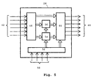
- FIG. 5 is a block diagram of the component parts in the control system 26 needed to perform this.
- the measured values for flow and pressure are sent to a measurement signal unit 44 in the control unit 26 via a number of measurement signal input terminals 42.
- Some signal processing, such as filtering, amplification, derivation and/or integration can be performed in the measurement signal unit 44. Integration of the flow signal provides a value for supplied, or outflow, gas volume to/from the connection system.
- the processed measurement signals are also digitized and then sent from the measurement signal unit 44 to a control unit 46.
- the signals are used in the control unit 46 for determining control of the ventilator unit 4, and control signals are emitted via a number of control signal output terminals 48.
- the control signals can consist of control signals for the inspiratory valves 14A, 14B, 14C and the expiratory valve 24.
- the control signals can also be used for controlling alarm functions and display units which are not shown but which are normally part of the ventilator unit 4.
- the Servo Ventilator 300 is a typical example of a modern ventilator containing a plurality of components and functions which need not be specified in this context.
- control unit 46 receives reference signals via a reference signal generator 52.
- the reference signal generator 52 is, in turn, connected to a reference input terminal 50 on some form of interface with a physician, i.e. a control panel used by the physician to program a target operating mode for the ventilator unit 4. This target operating mode is registered by the reference signal generator 52 which generates the requisite reference signals for controlling the ventilator unit 4.
- a compensation unit 54 is connected to the reference signal generator 52 and to the measurement signal unit 44.
- the compensation unit 54 is sent information on how the test gas to be generated is devised, i.e. which test gas flow pattern the test gas is to have, via the reference signal generator 52. This could involve e.g. sharp step functions or some form of so called colored noise.
- the test gas flow pattern could advantageously even contain all the gas flow patterns occurring in the operating modes which could be used with the breathing system.
- the compensation unit 54 then receives a response gas flow pattern from the measurement signal unit 44, i.e. the gas flow pattern ensuing after the influence of the connection system 6. As previously noted, this can consist of one or a plurality of the above-described models. With known input signals and known output signals for the connection system 6, the compensation unit 54 can then calculate the transfer function for the connection system 6, and this result is sent to the control unit 46 which can then compensate control of the ventilator unit 4 so the true gas flow pattern with which breathing gas is supplied to the patient is as similar as possible to the gas flow pattern selected by the physician.
- a diagnostic unit 56 is also arranged in the control unit 26.
- the diagnostic unit is connected to the measurement unit 44 and to the compensation unit 54.
- a plurality of different parameters can be accurately determined for the patient's lungs, e.g. resistance and compliance. This is accomplished as described above, i.e. when the diagnostic unit 56 receives factual measurement values from the signal unit 44, reference values for the target flow pattern for the breathing gas and the determined transfer function from the compensation unit 54.
- the target lung parameters are determined thereafter.
- the diagnostic unit 56 can also determine the patient's transfer function in the ventilator system 2.
- the block diagram in FIG. 2 only shows a schematic, functional structure for the control unit 26. It can be realized in different ways. The determinations can be made with hardware or software. Analog and digital elements can be combined when suitable.
- the control unit 26 also contains means for performing a plurality of unspecified functions necessary to the ventilator system's 2 operation.
- Another possible, direct application of the present invention concerns control of the expiratory valve 24 to maintain a predefined value for PEEP.
- an exhalation expiration
- the expiratory valve 24 opens completely to release gas from the respiratory system 8. In principle, this flow constitutes a step function. Flow will then decline in a way resembling a capacitor's discharge curve. Before flow ceases completely, the expiratory valve 24 is activated towards the closed position so as to maintain the predefined value for PEEP.
- a simplified transfer function for this specific phase of a breathing cycle is obtained by measuring the flow's time constant. The time constant can be used for improving regulation of the expiratory valve 24 so it can stay open longer while simultaneously maintaining the PEEP level with greater accuracy.
- transfer function models could be applied solely to pressure or flow.
- the test lung 58 could be devised in a plurality of ways, with or without meters. It could also be built into the ventilator unit 4. Other known model structures than the Box-Jenkins can be used. A number of model structures can be applied simultaneously, and the one displaying the greatest correlation between input signals and output signals for a given connection system is used.
- the device 2 can be devised so the transfer function is automatically determined every time the ventilator unit is activated, but it can also be devised so determination must be ordered by staff.
- the model structure for the transfer function can be non-linear of a higher order, as well as linear. Different transfer functions can be determined for special operating modes, or sub-stages, in the operation of the device 2.
Landscapes
- Health & Medical Sciences (AREA)
- Engineering & Computer Science (AREA)
- Life Sciences & Earth Sciences (AREA)
- Animal Behavior & Ethology (AREA)
- Anesthesiology (AREA)
- Biomedical Technology (AREA)
- Heart & Thoracic Surgery (AREA)
- Hematology (AREA)
- Emergency Medicine (AREA)
- Pulmonology (AREA)
- General Health & Medical Sciences (AREA)
- Public Health (AREA)
- Veterinary Medicine (AREA)
- Physics & Mathematics (AREA)
- General Physics & Mathematics (AREA)
- Automation & Control Theory (AREA)
- Measurement Of The Respiration, Hearing Ability, Form, And Blood Characteristics Of Living Organisms (AREA)
- Respiratory Apparatuses And Protective Means (AREA)
Claims (12)
- Procédé pour déterminer au moins une fonction de transfert décrivant la manière dont un système de raccordement (6) d'un appareil de ventilation (2), comprenant une unité de ventilation (4), influence un régime d'écoulement de gaz prédéfini et peut être utilisé pour compenser le réglage de la pression et du débit d'un gaz respiratoire, comprenant les étapes méthodologiques consistant à :raccorder le système de raccordement (6) à l'unité de ventilation (4) ;envoyer un gaz selon un premier régime d'écoulement de gaz test depuis une unité de régulation du gaz (12A, 12B, 12C, 14A, 14B, 14C, 18, 46) de l'unité de ventilation (4) ;mesurer, dans une unité de mesure (20, 22 ; 62, 64), un régime d'écoulement de gaz résultant obtenu pour le gaz ; etdéterminer la fonction de transfert à partir du régime d'écoulement de gaz test et du régime d'écoulement de gaz résultant.
- Procédé selon la revendication 1, caractérisé en ce qu'un modèle de poumon (58) ayant des caractéristiques connues est raccordé au système de raccordement (6) pour la détermination de la fonction de transfert.
- Procédé selon la revendication 1 ou 2, caractérisé en ce que le régime d'écoulement de gaz test affiche un spectre correspondant aux différents spectres de fréquences présents dans les modes de ventilation dans lesquels l'unité de ventilation (4) peut fonctionner.
- Procédé selon l'une quelconque des revendications précédentes, caractérisé en ce que la fonction de transfert est déterminée à partir d'un certain nombre de structures modèles préprogrammées, de préférence tant linéaires que non linéaires, où toutes les structures modèles sont adaptées aux valeurs de mesure, et la structure modèle affichant la corrélation la plus élevée est sélectionnée en tant que fonction de transfert.
- Procédé pour déterminer au moins une fonction de transfert décrivant la manière dont un système respiratoire (8) d'une créature vivante, raccordé à un appareil de ventilation (2) comprenant une unité de ventilation (4) destinée à être raccordée au système respiratoire (8) via un système de raccordement (6) destiné à envoyer et extraire un gaz respiratoire vers/depuis le système respiratoire (8) selon un régime d'écoulement de gaz prédéfini en ce qui concerne la pression et le débit, influence le régime d'écoulement de gaz prédéfini, comprenant les étapes méthodologiques consistant à :raccorder le système de raccordement (6) à l'unité de ventilation (4) ;envoyer un gaz selon un premier régime d'écoulement de gaz test depuis une unité de régulation du gaz (12A, 12B, 12C, 14A, 14B, 14C, 18, 46) de l'unité de ventilation (4) ;mesurer, dans une unité de mesure (20, 22 ; 62, 64), un premier régime d'écoulement de gaz résultant obtenu pour le gaz ;déterminer une première fonction de transfert à partir du premier régime d'écoulement de gaz test et du premier régime d'écoulement de gaz résultant ;après le raccordement du système de raccordement (6) au système respiratoire (8), envoyer un gaz selon un deuxième régime d'écoulement de gaz test depuis l'unité de régulation du gaz (12A, 12B, 12C, 14A, 14B, 14C, 18, 46) de l'unité de ventilation (4) ;mesurer, dans une unité de mesure (20, 22 ; 62, 64), un deuxième régime d'écoulement de gaz résultant obtenu pour le gaz ; etdéterminer l'influence du système respiratoire (8) sur le régime d'écoulement de gaz à partir du deuxième régime d'écoulement de gaz test, du deuxième régime d'écoulement de gaz résultant, et de la première fonction de transfert déterminée.
- Appareil (4, 6) pour envoyer et extraire un gaz respiratoire vers/depuis le système respiratoire (8) d'une créature vivante, comprenant une unité de ventilation (4) et un système de raccordement (6), raccordé à l'unité de ventilation (4) et pouvant être raccordé au système respiratoire (8), l'unité de ventilation (4) comprenant une unité de régulation du gaz (12A, 12B, 12C, 14A, 14B, 14C, 18, 46) comprenant au moins un débitmètre (12A, 12B, 12C) et un manomètre (18), disposés dans une branche inspiratoire de l'unité de ventilation (4), pour générer un flux de gaz respiratoire selon un régime d'écoulement de gaz donné, et une unité de mesure (20, 22 ; 58, 62, 64 ; 44), comprenant un débitmètre (22) et un manomètre (20), disposés dans une branche expiratoire de l'unité de ventilation (4), pour mesurer la pression et le débit, caractérisé par une unité de compensation (54), raccordée à l'unité de mesure (44) et à l'unité de régulation du gaz (46), l'unité de compensation (54) étant conçue pour déterminer la fonction de transfert du système de raccordement (6) en fonction du régime d'écoulement de gaz spécifique généré par l'unité de régulation du gaz (12A, 12B, 12C, 14A, 14B, 14C, 18, 46) et de la pression et du débit mesurés par l'unité de mesure (44).
- Appareil selon la revendication 6, caractérisé en ce que l'unité de compensation (54) détermine la fonction de transfert en utilisant les signaux de mesure provenant des appareils de mesure (12A, 12B, 12C, 18) de la branche inspiratoire en tant que signaux d'entrée du système de raccordement (6) et les signaux de mesure provenant des appareils de mesure (20, 22) de la branche expiratoire en tant que signaux de sortie.
- Appareil selon la revendication 7, caractérisé en ce qu'une unité de diagnostic (56) est raccordée à l'unité de mesure (44) et à l'unité de compensation (54) pour déterminer au moins un paramètre pulmonaire mécanique associé au système respiratoire (8) de la créature vivante.
- Appareil selon la revendication 8, caractérisé en ce que l'unité de diagnostic (56) détermine l'un des paramètres pulmonaires mécaniques que sont la résistance et la compliance, ou bien les deux.
- Appareil selon la revendication 6, caractérisé en ce que l'unité de mesure (58, 62, 64) comprend, en outre, un poumon test (58) pouvant être raccordé au système de raccordement (6), un débitmètre (62) et/ou un manomètre (64) disposés dans le poumon test (58) pour mesurer le débit et/ou la pression, et l'unité de compensation (54) détermine la fonction de transfert en utilisant les signaux de mesure provenant des appareils de mesure (12A, 12B, 12C, 20, 22, 18) des branches inspiratoire et expiratoire en tant que signaux d'entrée du système de raccordement et les signaux de mesure provenant des appareils de mesure (62, 64) du poumon test en tant que signaux de sortie.
- Appareil selon la revendication 10, caractérisé en ce que le poumon test est intégré dans l'unité de ventilation.
- Appareil selon la revendication 10 ou 11, caractérisé en ce que l'unité de compensation (54) est conçue pour calculer un facteur de compensation, qui peut être envoyé à l'unité de régulation du gaz (46), de façon que les changements survenant sous l'influence du système de raccordement (6) dans l'émission d'un flux de gaz respiratoire selon un régime d'écoulement de gaz déterminé soient compensés, et que le système respiratoire (8) reçoive un flux de gaz respiratoire ayant essentiellement le régime d'écoulement de gaz déterminé.
Applications Claiming Priority (2)
| Application Number | Priority Date | Filing Date | Title |
|---|---|---|---|
| SE9500275A SE9500275L (sv) | 1995-01-26 | 1995-01-26 | Metod och apparat för att bestämma en överföringsfunktion för ett anslutningssystem |
| SE9500275 | 1995-01-26 |
Publications (2)
| Publication Number | Publication Date |
|---|---|
| EP0723785A1 EP0723785A1 (fr) | 1996-07-31 |
| EP0723785B1 true EP0723785B1 (fr) | 2008-03-12 |
Family
ID=20396970
Family Applications (1)
| Application Number | Title | Priority Date | Filing Date |
|---|---|---|---|
| EP95119588A Expired - Lifetime EP0723785B1 (fr) | 1995-01-26 | 1995-12-12 | Méthode et dispositif de détermination de la fonction de transfert d'un système de connexion pour appareil d'assistance respiratoire |
Country Status (4)
| Country | Link |
|---|---|
| US (1) | US5743253A (fr) |
| EP (1) | EP0723785B1 (fr) |
| JP (1) | JP3679486B2 (fr) |
| SE (1) | SE9500275L (fr) |
Families Citing this family (47)
| Publication number | Priority date | Publication date | Assignee | Title |
|---|---|---|---|---|
| US6866040B1 (en) * | 1994-09-12 | 2005-03-15 | Nellcor Puritan Bennett France Developpement | Pressure-controlled breathing aid |
| US6158432A (en) | 1995-12-08 | 2000-12-12 | Cardiopulmonary Corporation | Ventilator control system and method |
| US6463930B2 (en) | 1995-12-08 | 2002-10-15 | James W. Biondi | System for automatically weaning a patient from a ventilator, and method thereof |
| SE9602913D0 (sv) * | 1996-08-02 | 1996-08-02 | Siemens Elema Ab | Ventilator system and method of operating a ventilator system |
| AUPO163896A0 (en) | 1996-08-14 | 1996-09-05 | Resmed Limited | Determination of respiratory airflow |
| US5881717A (en) | 1997-03-14 | 1999-03-16 | Nellcor Puritan Bennett Incorporated | System and method for adjustable disconnection sensitivity for disconnection and occlusion detection in a patient ventilator |
| US6309360B1 (en) | 1997-03-17 | 2001-10-30 | James R. Mault | Respiratory calorimeter |
| SE9704661D0 (sv) * | 1997-12-15 | 1997-12-15 | Siemens Elema Ab | Färskgassystem samt metod vid förgasning av flytande narkosmedel |
| US6572561B2 (en) | 1998-01-16 | 2003-06-03 | Healthetech, Inc. | Respiratory calorimeter |
| SE9801427D0 (sv) * | 1998-04-23 | 1998-04-23 | Siemens Elema Ab | Förfarande för bestämning av minst en parameter samt en andningsapparat |
| US6128963A (en) * | 1998-05-28 | 2000-10-10 | Instrumentarium Corp. | Gas flow restricting and sensing device |
| SE9802827D0 (sv) * | 1998-08-25 | 1998-08-25 | Siemens Elema Ab | Ventilator |
| DE19849571B4 (de) * | 1998-10-27 | 2004-12-02 | Map Medizin-Technologie Gmbh | Beatmungsgerät zur Zufuhr eines Atemgases zu einem Patienten unter einem auf den Patienten abgestimmten Behandlungsdruck |
| SE9902709D0 (sv) * | 1999-07-15 | 1999-07-15 | Siemens Elema Ab | Förfarande för styrning av en exspirationsventil i en ventilator |
| US6557553B1 (en) | 2000-09-05 | 2003-05-06 | Mallinckrodt, Inc. | Adaptive inverse control of pressure based ventilation |
| DE10352981B3 (de) * | 2003-11-13 | 2005-06-09 | Dräger Medical AG & Co. KGaA | Vorrichtung und Verfahren zur Versorgung eines Patienten mit Atemgas |
| SE528487C2 (sv) * | 2004-11-11 | 2006-11-28 | Transunit Ab | Exspiratorisk tryckregulator |
| US11833301B2 (en) | 2005-09-12 | 2023-12-05 | ResMed Pty Ltd | High flow therapy device utilizing a non-sealing respiratory interface and related methods |
| US11458270B2 (en) | 2005-09-12 | 2022-10-04 | ResMed Pty Ltd | High flow therapy device utilizing a non-sealing respiratory interface and related methods |
| US11696992B2 (en) | 2005-09-12 | 2023-07-11 | ResMed Pty Ltd | High flow therapy device utilizing a non-sealing respiratory interface and related methods |
| US11717174B2 (en) | 2005-09-12 | 2023-08-08 | ResMed Pty Ltd | High flow therapy device utilizing a non-sealing respiratory interface and related methods |
| US11497407B2 (en) | 2005-09-12 | 2022-11-15 | ResMed Pty Ltd | High flow therapy device utilizing a non-sealing respiratory interface and related methods |
| US20070283958A1 (en) * | 2006-05-23 | 2007-12-13 | Ray Naghavi | Positive airway pressure device |
| WO2008114334A1 (fr) * | 2007-02-21 | 2008-09-25 | Itswa Co., Ltd. | Appareil pour recycler l'humidité exhalée par un travailleur à l'intérieur d'une pièce sèche pour le travailleur |
| US20090165795A1 (en) * | 2007-12-31 | 2009-07-02 | Nellcor Puritan Bennett Llc | Method and apparatus for respiratory therapy |
| CN102056538B (zh) | 2008-06-06 | 2014-10-15 | 柯惠有限合伙公司 | 用于在换气系统中确定患者努力及/或呼吸参数的系统及方法 |
| US8302602B2 (en) | 2008-09-30 | 2012-11-06 | Nellcor Puritan Bennett Llc | Breathing assistance system with multiple pressure sensors |
| DE102009013396B3 (de) * | 2009-03-16 | 2010-08-05 | Dräger Medical AG & Co. KG | Vorrichtung und Verfahren zur Steuerung der Sauerstoffdosierung eines Beatmungsgerätes |
| US8714154B2 (en) | 2011-03-30 | 2014-05-06 | Covidien Lp | Systems and methods for automatic adjustment of ventilator settings |
| US8776792B2 (en) | 2011-04-29 | 2014-07-15 | Covidien Lp | Methods and systems for volume-targeted minimum pressure-control ventilation |
| US9993604B2 (en) | 2012-04-27 | 2018-06-12 | Covidien Lp | Methods and systems for an optimized proportional assist ventilation |
| US9375542B2 (en) | 2012-11-08 | 2016-06-28 | Covidien Lp | Systems and methods for monitoring, managing, and/or preventing fatigue during ventilation |
| US9358355B2 (en) | 2013-03-11 | 2016-06-07 | Covidien Lp | Methods and systems for managing a patient move |
| US11247015B2 (en) | 2015-03-24 | 2022-02-15 | Ventec Life Systems, Inc. | Ventilator with integrated oxygen production |
| US10315002B2 (en) | 2015-03-24 | 2019-06-11 | Ventec Life Systems, Inc. | Ventilator with integrated oxygen production |
| WO2016201358A1 (fr) | 2015-06-11 | 2016-12-15 | Revolutionary Medical Devices, Inc. | Masque de ventilation |
| US10773049B2 (en) | 2016-06-21 | 2020-09-15 | Ventec Life Systems, Inc. | Cough-assist systems with humidifier bypass |
| US10080521B2 (en) | 2016-08-01 | 2018-09-25 | Timothy Joshua Parrish | Sleep apnea bi-level positive airway pressure machine with advanced diagnostics and self-cleaning capabilities |
| EP3384948A1 (fr) * | 2017-04-04 | 2018-10-10 | Medec Benelux NV | Système et procédé d'étalonnage automatique de capteur de flux |
| CN110049799B (zh) | 2017-11-14 | 2022-04-26 | 柯惠有限合伙公司 | 用于驱动压力自发通气的方法和系统 |
| CN112105410A (zh) * | 2018-01-24 | 2020-12-18 | 菲舍尔和佩克尔保健有限公司 | 用于呼吸回路的医用管 |
| EP4470589A3 (fr) | 2018-05-13 | 2025-02-19 | Ventec Life Systems, Inc. | Système portable de ventilateur médical utilisant des concentrateurs portables d'oxygène |
| CN109011124B (zh) * | 2018-06-11 | 2021-02-09 | 朱学创 | 一种伤口消毒装置 |
| WO2020037509A1 (fr) * | 2018-08-21 | 2020-02-27 | 深圳迈瑞生物医疗电子股份有限公司 | Procédé et appareil de reconnaissance d'une anomalie touchant les voies respiratoires, dispositif de ventilation et support de stockage |
| US11517691B2 (en) | 2018-09-07 | 2022-12-06 | Covidien Lp | Methods and systems for high pressure controlled ventilation |
| JP2023548463A (ja) | 2020-11-06 | 2023-11-17 | ベンテック ライフ システムズ, インコーポレイテッド | 呼吸療法データ管理システム、デバイス、および方法 |
| JP2024503250A (ja) | 2020-12-21 | 2024-01-25 | ベンテック ライフ システムズ, インコーポレイテッド | 一体化された酸素送達を有するベンチレータシステムおよび関連付けられたデバイスおよび方法 |
Family Cites Families (6)
| Publication number | Priority date | Publication date | Assignee | Title |
|---|---|---|---|---|
| US4393869A (en) * | 1981-06-22 | 1983-07-19 | Canadian Patents & Development Limited | Electronically controlled respirator |
| JPS60107872U (ja) * | 1983-09-02 | 1985-07-22 | 伊藤精機株式会社 | 人工疑似肺装置 |
| US4991576A (en) * | 1988-10-11 | 1991-02-12 | Henkin Melvyn Lane | Anesthesia rebreathing system |
| US5365922A (en) * | 1991-03-19 | 1994-11-22 | Brigham And Women's Hospital, Inc. | Closed-loop non-invasive oxygen saturation control system |
| US5303698A (en) * | 1991-08-27 | 1994-04-19 | The Boc Group, Inc. | Medical ventilator |
| GB9307733D0 (en) * | 1993-04-14 | 1993-06-02 | Msa Britain Ltd | Respiratory protective device |
-
1995
- 1995-01-26 SE SE9500275A patent/SE9500275L/xx not_active Application Discontinuation
- 1995-12-12 EP EP95119588A patent/EP0723785B1/fr not_active Expired - Lifetime
-
1996
- 1996-01-19 US US08/588,684 patent/US5743253A/en not_active Expired - Lifetime
- 1996-01-26 JP JP01185996A patent/JP3679486B2/ja not_active Expired - Fee Related
Non-Patent Citations (1)
| Title |
|---|
| None * |
Also Published As
| Publication number | Publication date |
|---|---|
| SE9500275L (sv) | 1996-07-27 |
| JP3679486B2 (ja) | 2005-08-03 |
| SE9500275D0 (sv) | 1995-01-26 |
| US5743253A (en) | 1998-04-28 |
| EP0723785A1 (fr) | 1996-07-31 |
| JPH08229129A (ja) | 1996-09-10 |
Similar Documents
| Publication | Publication Date | Title |
|---|---|---|
| EP0723785A1 (fr) | Méthode et dispositif de détermination de la fonction de transfert d'un système de connexion pour appareil d'assistance respiratoire | |
| US5878744A (en) | Ventilator system and method of operating a ventilating system | |
| US6253765B1 (en) | Method for determining the volume of a tubing system and a breathing apparatus system | |
| EP1295620B1 (fr) | Appareil respiratoire pour l'utilisation dans l'examen des caractéristiques mécaniques d'un système respiratoire | |
| US11464934B2 (en) | Gas delivery method and apparatus | |
| US6820613B2 (en) | Process and device for controlling the breathing gas supply | |
| DE60033471T2 (de) | Verfahren zur messung der funktionellen residualkapazität | |
| US6679258B1 (en) | Ventilator operable in a compensated volume support mode | |
| US11850358B2 (en) | Smart control system and method based on machine learning for modulating end-tidal concentration levels by means of adjustments to the volume and concentration of an incoming respiratory gas flow in real time | |
| DE69624773T2 (de) | Gerät zur Unterstützung der Atmung | |
| EP1957139B1 (fr) | Appareil permettant d'estimer le volume pulmonaire en fin d'expiration | |
| US20130006133A1 (en) | Methods and systems for monitoring volumetric carbon dioxide | |
| US20130006134A1 (en) | Methods and systems for monitoring volumetric carbon dioxide | |
| DE60037636T2 (de) | Verfahren zur Beurteilung von pulmonarem Stress und eine Atmungsvorrichtung | |
| US7086098B2 (en) | Mechanical breathing aid with adaptive expiration control | |
| US20090183737A1 (en) | Pulse width modulated medical gas concentration control | |
| EP4181991A1 (fr) | Ventilateur et procédé pour déterminer au moins une pression alvéolaire et/ou un profil d'une pression alvéolaire dans les voies respiratoires d'un patient | |
| DE60300344T2 (de) | Verfahren und Vorrichtung zur Überwachung der Zusammensetzung eines zweikomponentigen Atemgasgemisches | |
| US6840241B2 (en) | Apparatus for determination of recruitable volume of a lung | |
| Mecklenburgh et al. | A model lung with direct representation of respiratory muscle activity | |
| HK40073070A (en) | Gas delivery apparatus | |
| HK40073070B (en) | Gas delivery apparatus |
Legal Events
| Date | Code | Title | Description |
|---|---|---|---|
| PUAI | Public reference made under article 153(3) epc to a published international application that has entered the european phase |
Free format text: ORIGINAL CODE: 0009012 |
|
| AK | Designated contracting states |
Kind code of ref document: A1 Designated state(s): CH ES FR GB IT LI NL SE |
|
| 17P | Request for examination filed |
Effective date: 19960904 |
|
| 17Q | First examination report despatched |
Effective date: 19990628 |
|
| RAP1 | Party data changed (applicant data changed or rights of an application transferred) |
Owner name: MAQUET CRITICAL CARE AB |
|
| APAF | Appeal reference modified |
Free format text: ORIGINAL CODE: EPIDOSCREFNE |
|
| APBT | Appeal procedure closed |
Free format text: ORIGINAL CODE: EPIDOSNNOA9E |
|
| GRAP | Despatch of communication of intention to grant a patent |
Free format text: ORIGINAL CODE: EPIDOSNIGR1 |
|
| GRAS | Grant fee paid |
Free format text: ORIGINAL CODE: EPIDOSNIGR3 |
|
| GRAA | (expected) grant |
Free format text: ORIGINAL CODE: 0009210 |
|
| AK | Designated contracting states |
Kind code of ref document: B1 Designated state(s): CH ES FR GB IT LI NL SE |
|
| REG | Reference to a national code |
Ref country code: GB Ref legal event code: FG4D |
|
| REG | Reference to a national code |
Ref country code: CH Ref legal event code: EP |
|
| NLV1 | Nl: lapsed or annulled due to failure to fulfill the requirements of art. 29p and 29m of the patents act | ||
| PG25 | Lapsed in a contracting state [announced via postgrant information from national office to epo] |
Ref country code: SE Free format text: LAPSE BECAUSE OF FAILURE TO SUBMIT A TRANSLATION OF THE DESCRIPTION OR TO PAY THE FEE WITHIN THE PRESCRIBED TIME-LIMIT Effective date: 20080612 Ref country code: ES Free format text: LAPSE BECAUSE OF FAILURE TO SUBMIT A TRANSLATION OF THE DESCRIPTION OR TO PAY THE FEE WITHIN THE PRESCRIBED TIME-LIMIT Effective date: 20080623 |
|
| PG25 | Lapsed in a contracting state [announced via postgrant information from national office to epo] |
Ref country code: NL Free format text: LAPSE BECAUSE OF FAILURE TO SUBMIT A TRANSLATION OF THE DESCRIPTION OR TO PAY THE FEE WITHIN THE PRESCRIBED TIME-LIMIT Effective date: 20080312 |
|
| ET | Fr: translation filed | ||
| PLBE | No opposition filed within time limit |
Free format text: ORIGINAL CODE: 0009261 |
|
| STAA | Information on the status of an ep patent application or granted ep patent |
Free format text: STATUS: NO OPPOSITION FILED WITHIN TIME LIMIT |
|
| 26N | No opposition filed |
Effective date: 20081215 |
|
| REG | Reference to a national code |
Ref country code: CH Ref legal event code: PL |
|
| GBPC | Gb: european patent ceased through non-payment of renewal fee |
Effective date: 20081212 |
|
| PG25 | Lapsed in a contracting state [announced via postgrant information from national office to epo] |
Ref country code: IT Free format text: LAPSE BECAUSE OF FAILURE TO SUBMIT A TRANSLATION OF THE DESCRIPTION OR TO PAY THE FEE WITHIN THE PRESCRIBED TIME-LIMIT Effective date: 20080312 |
|
| PG25 | Lapsed in a contracting state [announced via postgrant information from national office to epo] |
Ref country code: LI Free format text: LAPSE BECAUSE OF NON-PAYMENT OF DUE FEES Effective date: 20081231 Ref country code: CH Free format text: LAPSE BECAUSE OF NON-PAYMENT OF DUE FEES Effective date: 20081231 |
|
| PG25 | Lapsed in a contracting state [announced via postgrant information from national office to epo] |
Ref country code: GB Free format text: LAPSE BECAUSE OF NON-PAYMENT OF DUE FEES Effective date: 20081212 |
|
| PGFP | Annual fee paid to national office [announced via postgrant information from national office to epo] |
Ref country code: FR Payment date: 20131231 Year of fee payment: 19 |
|
| REG | Reference to a national code |
Ref country code: FR Ref legal event code: ST Effective date: 20150831 |
|
| PG25 | Lapsed in a contracting state [announced via postgrant information from national office to epo] |
Ref country code: FR Free format text: LAPSE BECAUSE OF NON-PAYMENT OF DUE FEES Effective date: 20141231 |