EP0723829B1 - Vorrichtung zum Einsetzen einer Abdeckplatte in einer Zufuhr- und Austauschvorrichtung eines Tauchrohres - Google Patents
Vorrichtung zum Einsetzen einer Abdeckplatte in einer Zufuhr- und Austauschvorrichtung eines Tauchrohres Download PDFInfo
- Publication number
- EP0723829B1 EP0723829B1 EP95870022A EP95870022A EP0723829B1 EP 0723829 B1 EP0723829 B1 EP 0723829B1 EP 95870022 A EP95870022 A EP 95870022A EP 95870022 A EP95870022 A EP 95870022A EP 0723829 B1 EP0723829 B1 EP 0723829B1
- Authority
- EP
- European Patent Office
- Prior art keywords
- pouring
- trajectory
- plate
- emergency
- mobile frame
- Prior art date
- Legal status (The legal status is an assumption and is not a legal conclusion. Google has not performed a legal analysis and makes no representation as to the accuracy of the status listed.)
- Expired - Lifetime
Links
- 238000005266 casting Methods 0.000 title abstract description 13
- 230000037431 insertion Effects 0.000 title 1
- 238000003780 insertion Methods 0.000 title 1
- 239000002184 metal Substances 0.000 claims description 3
- 238000009434 installation Methods 0.000 description 3
- 229910000831 Steel Inorganic materials 0.000 description 1
- 238000009749 continuous casting Methods 0.000 description 1
- JEIPFZHSYJVQDO-UHFFFAOYSA-N iron(III) oxide Inorganic materials O=[Fe]O[Fe]=O JEIPFZHSYJVQDO-UHFFFAOYSA-N 0.000 description 1
- 238000002360 preparation method Methods 0.000 description 1
- 239000010959 steel Substances 0.000 description 1
Images



Classifications
-
- B—PERFORMING OPERATIONS; TRANSPORTING
- B22—CASTING; POWDER METALLURGY
- B22D—CASTING OF METALS; CASTING OF OTHER SUBSTANCES BY THE SAME PROCESSES OR DEVICES
- B22D41/00—Casting melt-holding vessels, e.g. ladles, tundishes, cups or the like
- B22D41/14—Closures
- B22D41/22—Closures sliding-gate type, i.e. having a fixed plate and a movable plate in sliding contact with each other for selective registry of their openings
- B22D41/24—Closures sliding-gate type, i.e. having a fixed plate and a movable plate in sliding contact with each other for selective registry of their openings characterised by a rectilinearly movable plate
-
- B—PERFORMING OPERATIONS; TRANSPORTING
- B22—CASTING; POWDER METALLURGY
- B22D—CASTING OF METALS; CASTING OF OTHER SUBSTANCES BY THE SAME PROCESSES OR DEVICES
- B22D41/00—Casting melt-holding vessels, e.g. ladles, tundishes, cups or the like
- B22D41/14—Closures
- B22D41/22—Closures sliding-gate type, i.e. having a fixed plate and a movable plate in sliding contact with each other for selective registry of their openings
- B22D41/42—Features relating to gas injection
-
- B—PERFORMING OPERATIONS; TRANSPORTING
- B22—CASTING; POWDER METALLURGY
- B22D—CASTING OF METALS; CASTING OF OTHER SUBSTANCES BY THE SAME PROCESSES OR DEVICES
- B22D41/00—Casting melt-holding vessels, e.g. ladles, tundishes, cups or the like
- B22D41/50—Pouring-nozzles
- B22D41/56—Means for supporting, manipulating or changing a pouring-nozzle
-
- Y—GENERAL TAGGING OF NEW TECHNOLOGICAL DEVELOPMENTS; GENERAL TAGGING OF CROSS-SECTIONAL TECHNOLOGIES SPANNING OVER SEVERAL SECTIONS OF THE IPC; TECHNICAL SUBJECTS COVERED BY FORMER USPC CROSS-REFERENCE ART COLLECTIONS [XRACs] AND DIGESTS
- Y10—TECHNICAL SUBJECTS COVERED BY FORMER USPC
- Y10S—TECHNICAL SUBJECTS COVERED BY FORMER USPC CROSS-REFERENCE ART COLLECTIONS [XRACs] AND DIGESTS
- Y10S266/00—Metallurgical apparatus
- Y10S266/01—Repair or restoration of apparatus
Definitions
- the present invention relates to an emergency shutter of a supply device and pouring tube exchange applied sealingly against the fixed underside of a refractory reference plate housed in the frame of the device fixed to a container of metal pouring from the bottom, under the upward push of guide rails which determine a rectilinear trajectory along which the pouring tubes slide, under the action of a jack, from a loading position to a service in the casting axis and from the service position to a position of release.
- Removing the blind plate was, however, a relatively straightforward operation. complicated due to the extreme temperatures prevailing near the axis of risk of forgetting to put it back in place or losing it in the mold by a wrong maneuver during preparations for loading the tube replacement.
- the present invention aims to facilitate the establishment and removal of a plate shutter refractory during and after the pouring tube change operation of a continuous casting installation. To this end, it offers a shutter Emergency of the type described in the preamble to claim 1 attached.
- This shutter is characterized in that it consists of a plate on which is deposited a blind refractory plate to be moved along a second path which intersects the first aforementioned trajectory, from a positioning position availability outside the second trajectory to an alert position on the right a trajectory overlap zone, adjacent to the service position of a pouring tube in the pouring axis.
- the aforementioned trajectories are parallel to the fixed underside of the reference plate and included in the same plane horizontal.
- the movable plate is a rotating plate by means of a rotary arm articulated to a frame of the supply and exchange device pouring tubes, around a vertical axis.
- the movable tray is a tray-drawer sliding along straight guides fixed to the frame parallel to the plate reference refractory.
- the movable plate is provided with a handle and / or a drawer or handle more accessible to an operator than the movable tray itself to manually operate it.
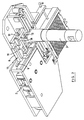
- a supply and exchange device 2 of pouring tubes without however representing the mold in which should have immerse the pouring tube 3 shown in the service position in the casting axis.
- This tube 3 is attached to a plate 4 applied sealingly against a lower face fixed of a reference refractory plate 5 applied against the frame of the device 2.
- a upward pushing force is exerted on the plate 4 by guide rails 6 and 7.
- the fixed guides 19 and 20 determine a first trajectory of the tube replacement and the tube to be replaced.
- a blind refractory plate 8 which adjoins the tube 3 in the service position in the casting axis.
- the plate shutter 8 is at work to be instantly moved under the push a retractable arm 9 of a pneumatic cylinder, as described in the patent EP-B-0192019, in the casting axis, to replace the pouring tube that it has itself pushed back by pressing along a common transverse rim.
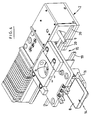
- a complete closure device 10 incorporated into the frame of the supply device and exchange of pouring tubes in the immediate vicinity of the guide rails 6, 7 is capable to deposit and remove, at will, the blind refractory plate 8 from a positioning position on availability 14 to an alert position 15 connected to the service position and vice-versa.
- the shutter 10 consists of a movable plate 11 on which the blind refractory plate 8.
- the movable plate 11 moves the blind refractory plate 8 along a second trajectory which intersects the above-mentioned first trajectory, from a standby position 14 outside the second trajectory towards a alert position 15 in line with an overlap zone of the two trajectories, adjacent to the service position of a pouring tube in the casting axis.
- the plate mobile 11 is a tray-drawer sliding along rectilinear guides 12 and 13 fixed to the frame of the device for supplying and exchanging pouring tubes.
- the movable platform is provided with a handle 17 and a drawbar or handle 18 more accessible to an operator than the movable plate 11 itself for manually actuating it.
Landscapes
- Engineering & Computer Science (AREA)
- Mechanical Engineering (AREA)
- Furnace Housings, Linings, Walls, And Ceilings (AREA)
- Battery Electrode And Active Subsutance (AREA)
- Continuous Casting (AREA)
- Supplying Of Containers To The Packaging Station (AREA)
- Feeding Of Articles To Conveyors (AREA)
- Chutes (AREA)
Claims (7)
- Notverschluss (10) für eine Vorrichtung (2) zum Zuführen und Austauschen von Gießrohren (3) und dicht gegen die Unterseite einer feststehenden Bezugs-Feuerfestplatte angedrückt, die in dem an einem Gefäß (1) zum Gießen von Metall durch den Boden befestigten Gestell der Vorrichtung gelagert ist, unter dem nach oben gerichteten Druck von Führungsschienen (6, 7), die eine erste geradlinige Bewegungsbahn festlegen, entlang von welcher jede der an die besagten Gießrohre angefügten Platten (4) unter der Einwirkung eines Zylinders aus einer Beschickungsposition in eine Betriebsposition in der Gießachse und aus der Betriebsposition in eine Freigabeposition gleitet, dadurch gekennzeichnet, dass er aus einer beweglichen Plattform (11) besteht, auf der eine Blind-Feuerfestplatte (8) abgelegt ist, im Hinblick darauf, sie entlang einer zweiten Bewegungsbahn, welche die oben genannte erste Bewegungsbahn überschneidet, aus einer Bereitstellungsposition (14) außerhalb der zweiten Bewegungsbahn in eine Bereitschaftsposition (15) geradeaus von einer Überdeckungszone der beiden Bewegungsbahnen zu verschieben, die an die Betriebsposition eines Gießrohrs (3) in der Gießachse angrenzt.
- Notverschluss nach Anspruch 1, dadurch gekennzeichnet, dass die oben genannten Bewegungsbahnen parallel zur feststehenden Unterseite der Bezugsplatte (5) und in einer selben Horizontalebene enthalten sind.
- Notverschluss nach Anspruch 1 oder 2, dadurch gekennzeichnet, dass die bewegliche Plattform (11) und die Führungsschienen (6, 7) in einer selben Horizontalebene enthaltene Auflageflächen aufweisen.
- Notverschluss nach einem der vorangehenden Ansprüche, dadurch gekennzeichnet, dass die bewegliche Plattform (11) eine Platte ist, die sich mittels eines Dreharms (16) dreht, der um eine vertikale Achsen schwenkbar an einem Gestell der Vorrichtung zum Zuführen und Austauschen von Gießrohren angelenkt ist.
- Notverschluss nach einem der Ansprüche 1 bis 4, dadurch gekennzeichnet, dass die bewegliche Plattform (11) eine Schiebeplattform ist, die sich entlang von gestellfesten geradlinigen Führungen (12, 13) verschiebt.
- Notverschluss nach einem der vorangehenden Ansprüche, dadurch gekennzeichnet, dass die bewegliche Plattform (11) mit einem Griff (17) und mit einer Deichsel oder Griffstange (18) versehen ist, die für eine Bedienungsperson leichter als die bewegliche Plattform (11) selbst zugänglich ist, um diese von Hand zu betätigen.
- Notverschluss nach einem der vorangehenden Ansprüche, dadurch gekennzeichnet, dass die bewegliche Plattform (11) durch einen ferngesteuerten Zylinder betätigt wird.
Applications Claiming Priority (2)
| Application Number | Priority Date | Filing Date | Title |
|---|---|---|---|
| US377206 | 1995-01-24 | ||
| US08/377,206 US5494201A (en) | 1995-01-24 | 1995-01-24 | Device for inserting a retractable blank shutting off plate in a device for the conveyance and exchange of a pouring tube |
Publications (2)
| Publication Number | Publication Date |
|---|---|
| EP0723829A1 EP0723829A1 (de) | 1996-07-31 |
| EP0723829B1 true EP0723829B1 (de) | 1999-12-01 |
Family
ID=23488181
Family Applications (1)
| Application Number | Title | Priority Date | Filing Date |
|---|---|---|---|
| EP95870022A Expired - Lifetime EP0723829B1 (de) | 1995-01-24 | 1995-03-16 | Vorrichtung zum Einsetzen einer Abdeckplatte in einer Zufuhr- und Austauschvorrichtung eines Tauchrohres |
Country Status (6)
| Country | Link |
|---|---|
| US (1) | US5494201A (de) |
| EP (1) | EP0723829B1 (de) |
| AT (1) | ATE187110T1 (de) |
| DE (1) | DE69513627T2 (de) |
| DK (1) | DK0723829T3 (de) |
| ES (1) | ES2141912T3 (de) |
Cited By (1)
| Publication number | Priority date | Publication date | Assignee | Title |
|---|---|---|---|---|
| DE10213041C1 (de) * | 2002-03-22 | 2003-11-13 | Uwe Bovenschen | Gießpfannen-Schieberverschluss-System |
Families Citing this family (8)
| Publication number | Priority date | Publication date | Assignee | Title |
|---|---|---|---|---|
| FR2716819B1 (fr) * | 1994-03-04 | 1996-04-05 | Vesuvius France Sa | Procédé et dispositif de coulée. |
| FR2760667B1 (fr) * | 1997-03-14 | 1999-05-28 | Int Ind Eng Sa | Dispositif obturateur-regulateur de coulee continue a chaud, avec echangeur de busette perfectionne |
| EP2319640A1 (de) | 2009-10-21 | 2011-05-11 | Vesuvius Group S.A | Tauschgiessrohr für Metallschmelze sowie Zusammensetzung dessen mit einer Ausgussdüse |
| RU2600461C2 (ru) * | 2011-01-11 | 2016-10-20 | Штопинк Акциенгезелльшафт | Механизм замены разливочной трубы с пластиной-заглушкой для разливочного устройства для производства металлургических продуктов |
| CN103862009B (zh) * | 2014-02-28 | 2016-05-18 | 北京首钢股份有限公司 | 异钢种连浇自动插铁板的装置和方法 |
| BR102017022985B1 (pt) | 2017-10-25 | 2022-11-08 | Magnesita Refratários S.A. | Mecanismo e método para substituição de válvula de lingotamento contínuo e método para vedação do furo de vazamento do mecanismo de substituição de válvula |
| WO2021110259A1 (en) | 2019-12-04 | 2021-06-10 | Refractory Intellectual Property Gmbh & Co. Kg | Refractory casting nozzle for a changing device arranged at the outlet of a metallurgical vessel |
| JP2023170217A (ja) * | 2022-05-18 | 2023-12-01 | 黒崎播磨株式会社 | 浸漬ノズル交換装置 |
Family Cites Families (7)
| Publication number | Priority date | Publication date | Assignee | Title |
|---|---|---|---|---|
| GB1597215A (en) * | 1978-04-24 | 1981-09-03 | Vesuvius Int Corp | Device for replacing pouring tubes |
| US4693401A (en) * | 1984-07-28 | 1987-09-15 | Kurosaki Refractories Co., Ltd. | Apparatus for compressively holding casting nozzles |
| US5188743A (en) * | 1989-03-03 | 1993-02-23 | Flo-Con Systems, Inc. | Plate, changer, plate and method |
| WO1992000821A1 (fr) * | 1990-07-04 | 1992-01-23 | International Industrial Engineering S.A. | Dispositif ameliore d'amenee et d'echange d'un tube de coulee |
| BE1004092A3 (fr) * | 1990-12-19 | 1992-09-22 | Internat Ind Engineering S A | Dispositif d'amenee et d'echange d'un tube de coulee. |
| BE1006191A3 (fr) * | 1992-09-30 | 1994-06-07 | Int Ind Eng Sa | Bras-pousseur eclipsable d'un dispositif d'amenee et d'echange de tubes de coulee. |
| BE1007317A3 (fr) * | 1993-07-27 | 1995-05-16 | Int Ind Eng Sa | Dispositif d'amenee et d'echange d'un tube de coulee dans une installation de coulee continue a brames minces. |
-
1995
- 1995-01-24 US US08/377,206 patent/US5494201A/en not_active Expired - Fee Related
- 1995-03-16 ES ES95870022T patent/ES2141912T3/es not_active Expired - Lifetime
- 1995-03-16 DE DE69513627T patent/DE69513627T2/de not_active Expired - Fee Related
- 1995-03-16 AT AT95870022T patent/ATE187110T1/de not_active IP Right Cessation
- 1995-03-16 DK DK95870022T patent/DK0723829T3/da active
- 1995-03-16 EP EP95870022A patent/EP0723829B1/de not_active Expired - Lifetime
Cited By (1)
| Publication number | Priority date | Publication date | Assignee | Title |
|---|---|---|---|---|
| DE10213041C1 (de) * | 2002-03-22 | 2003-11-13 | Uwe Bovenschen | Gießpfannen-Schieberverschluss-System |
Also Published As
| Publication number | Publication date |
|---|---|
| DE69513627T2 (de) | 2000-05-04 |
| ES2141912T3 (es) | 2000-04-01 |
| EP0723829A1 (de) | 1996-07-31 |
| DK0723829T3 (da) | 2000-05-29 |
| US5494201A (en) | 1996-02-27 |
| DE69513627D1 (de) | 2000-01-05 |
| ATE187110T1 (de) | 1999-12-15 |
Similar Documents
| Publication | Publication Date | Title |
|---|---|---|
| EP0537195B1 (de) | Zufuhr- und austauschvorrichtung eines tauchrohres | |
| EP0723829A1 (de) | Vorrichtung zum Einsetzen einer Abdeckplatte in einer Zufuhr- und Austauschvorrichtung eines Tauchrohres | |
| US5688425A (en) | Submerged nozzle changing apparatus | |
| BE1007317A3 (fr) | Dispositif d'amenee et d'echange d'un tube de coulee dans une installation de coulee continue a brames minces. | |
| US12042856B2 (en) | Robotized ladle transportation device system with embedded manipulator | |
| EP0621098B1 (de) | Vorrichtung und Verfahren zum Giessen mit einer zementfreien Verbindung des Schiebeverschlusses mit dem metallurgischen Gefäss | |
| KR20220140771A (ko) | 로봇식 래들 터렛 시스템 | |
| EP0825910B1 (de) | Vorrichtung und verfahren zum welchseln eines tauchrohres am zwischengefäss einer stranggussanlage für stahl | |
| EP0020554A1 (de) | Steuerung und verriegelung der drehenden weiche für pneumatische rohrtransportvorrichtungen. | |
| EP3898030B1 (de) | Robotersystem zum wechseln einer gleitschieberventilplatte | |
| FR2707190A3 (fr) | Dispositif pour le raccordement et le remplacement d'une busette de coulée sur une cuve contenant un bain de métal en fusion. | |
| GB1561959A (en) | Bottom pour vessel and shroulding apparatus | |
| US5942147A (en) | Submerged nozzle replacing device | |
| BE1006191A3 (fr) | Bras-pousseur eclipsable d'un dispositif d'amenee et d'echange de tubes de coulee. | |
| CA2138155C (fr) | Dispositif de regulation d'un debit de coulee | |
| FR2562448A1 (fr) | Dispositif de manipulation d'un tube de protection d'un jet de coulee | |
| JPWO1997028917A1 (ja) | 浸漬ノズル交換装置 | |
| CA2568762C (en) | Valve assembly extraction tool | |
| EP0248742B1 (de) | Verfahren zum Reinigen der Abstichöffnung bei einem Stahlwerksofen mit Erkerabstich | |
| MXPA97008487A (en) | Device and process to change a continuous decolated tube of a distributor of an ac laminator | |
| FR2938507A1 (fr) | Machine pour la fermeture de contenants | |
| EP0498684A1 (de) | Ausstosseinrichtung für eine Giessschutzrohr-Trageinrichtung in eine Stranggiessvorrichtung | |
| JPH0413457A (ja) | 管の引抜き方法 | |
| JP2002066700A (ja) | 浸漬ノズルハンドリング装置 | |
| LU88042A1 (fr) | Procede d'introduction d'une tige de percage dans le trou de coulee d'un four a cuve,machine de percage et pince prevue pour une telle machine |
Legal Events
| Date | Code | Title | Description |
|---|---|---|---|
| PUAI | Public reference made under article 153(3) epc to a published international application that has entered the european phase |
Free format text: ORIGINAL CODE: 0009012 |
|
| AK | Designated contracting states |
Kind code of ref document: A1 Designated state(s): AT BE CH DE DK ES FR GB GR IT LI LU NL SE |
|
| 17P | Request for examination filed |
Effective date: 19961207 |
|
| GRAG | Despatch of communication of intention to grant |
Free format text: ORIGINAL CODE: EPIDOS AGRA |
|
| 17Q | First examination report despatched |
Effective date: 19980812 |
|
| GRAG | Despatch of communication of intention to grant |
Free format text: ORIGINAL CODE: EPIDOS AGRA |
|
| GRAG | Despatch of communication of intention to grant |
Free format text: ORIGINAL CODE: EPIDOS AGRA |
|
| GRAH | Despatch of communication of intention to grant a patent |
Free format text: ORIGINAL CODE: EPIDOS IGRA |
|
| RAP1 | Party data changed (applicant data changed or rights of an application transferred) |
Owner name: INTERNATIONAL INDUSTRIAL ENGINEERING S.A. |
|
| GRAH | Despatch of communication of intention to grant a patent |
Free format text: ORIGINAL CODE: EPIDOS IGRA |
|
| RTI1 | Title (correction) |
Free format text: DEVICE FOR INSERTING A BLANK PLATE IN A CASTING TUBE INSERTION AND REPLACEMENT DEVICE |
|
| GRAH | Despatch of communication of intention to grant a patent |
Free format text: ORIGINAL CODE: EPIDOS IGRA |
|
| GRAA | (expected) grant |
Free format text: ORIGINAL CODE: 0009210 |
|
| AK | Designated contracting states |
Kind code of ref document: B1 Designated state(s): AT BE CH DE DK ES FR GB GR IT LI LU NL SE |
|
| PG25 | Lapsed in a contracting state [announced via postgrant information from national office to epo] |
Ref country code: GR Free format text: LAPSE BECAUSE OF NON-PAYMENT OF DUE FEES Effective date: 19991201 |
|
| REF | Corresponds to: |
Ref document number: 187110 Country of ref document: AT Date of ref document: 19991215 Kind code of ref document: T |
|
| REG | Reference to a national code |
Ref country code: CH Ref legal event code: EP |
|
| REF | Corresponds to: |
Ref document number: 69513627 Country of ref document: DE Date of ref document: 20000105 |
|
| ITF | It: translation for a ep patent filed | ||
| GBT | Gb: translation of ep patent filed (gb section 77(6)(a)/1977) |
Effective date: 20000207 |
|
| REG | Reference to a national code |
Ref country code: ES Ref legal event code: FG2A Ref document number: 2141912 Country of ref document: ES Kind code of ref document: T3 |
|
| REG | Reference to a national code |
Ref country code: DK Ref legal event code: T3 |
|
| PLBE | No opposition filed within time limit |
Free format text: ORIGINAL CODE: 0009261 |
|
| STAA | Information on the status of an ep patent application or granted ep patent |
Free format text: STATUS: NO OPPOSITION FILED WITHIN TIME LIMIT |
|
| 26N | No opposition filed | ||
| REG | Reference to a national code |
Ref country code: GB Ref legal event code: IF02 |
|
| PGFP | Annual fee paid to national office [announced via postgrant information from national office to epo] |
Ref country code: DK Payment date: 20040123 Year of fee payment: 10 |
|
| PGFP | Annual fee paid to national office [announced via postgrant information from national office to epo] |
Ref country code: NL Payment date: 20040229 Year of fee payment: 10 |
|
| PGFP | Annual fee paid to national office [announced via postgrant information from national office to epo] |
Ref country code: AT Payment date: 20040303 Year of fee payment: 10 |
|
| PGFP | Annual fee paid to national office [announced via postgrant information from national office to epo] |
Ref country code: GB Payment date: 20040310 Year of fee payment: 10 |
|
| PGFP | Annual fee paid to national office [announced via postgrant information from national office to epo] |
Ref country code: FR Payment date: 20040318 Year of fee payment: 10 |
|
| PGFP | Annual fee paid to national office [announced via postgrant information from national office to epo] |
Ref country code: SE Payment date: 20040319 Year of fee payment: 10 |
|
| PGFP | Annual fee paid to national office [announced via postgrant information from national office to epo] |
Ref country code: CH Payment date: 20040322 Year of fee payment: 10 |
|
| PGFP | Annual fee paid to national office [announced via postgrant information from national office to epo] |
Ref country code: LU Payment date: 20040324 Year of fee payment: 10 |
|
| PGFP | Annual fee paid to national office [announced via postgrant information from national office to epo] |
Ref country code: ES Payment date: 20040407 Year of fee payment: 10 |
|
| PGFP | Annual fee paid to national office [announced via postgrant information from national office to epo] |
Ref country code: DE Payment date: 20040430 Year of fee payment: 10 |
|
| PGFP | Annual fee paid to national office [announced via postgrant information from national office to epo] |
Ref country code: BE Payment date: 20040511 Year of fee payment: 10 |
|
| PG25 | Lapsed in a contracting state [announced via postgrant information from national office to epo] |
Ref country code: IT Free format text: LAPSE BECAUSE OF NON-PAYMENT OF DUE FEES Effective date: 20050316 Ref country code: GB Free format text: LAPSE BECAUSE OF NON-PAYMENT OF DUE FEES Effective date: 20050316 Ref country code: AT Free format text: LAPSE BECAUSE OF NON-PAYMENT OF DUE FEES Effective date: 20050316 |
|
| PG25 | Lapsed in a contracting state [announced via postgrant information from national office to epo] |
Ref country code: SE Free format text: LAPSE BECAUSE OF NON-PAYMENT OF DUE FEES Effective date: 20050317 Ref country code: ES Free format text: LAPSE BECAUSE OF NON-PAYMENT OF DUE FEES Effective date: 20050317 |
|
| PG25 | Lapsed in a contracting state [announced via postgrant information from national office to epo] |
Ref country code: LI Free format text: LAPSE BECAUSE OF NON-PAYMENT OF DUE FEES Effective date: 20050331 Ref country code: DK Free format text: LAPSE BECAUSE OF NON-PAYMENT OF DUE FEES Effective date: 20050331 Ref country code: CH Free format text: LAPSE BECAUSE OF NON-PAYMENT OF DUE FEES Effective date: 20050331 Ref country code: BE Free format text: LAPSE BECAUSE OF NON-PAYMENT OF DUE FEES Effective date: 20050331 |
|
| BERE | Be: lapsed |
Owner name: S.A. *VESUVIUS GROUP Effective date: 20050331 |
|
| PG25 | Lapsed in a contracting state [announced via postgrant information from national office to epo] |
Ref country code: NL Free format text: LAPSE BECAUSE OF NON-PAYMENT OF DUE FEES Effective date: 20051001 Ref country code: DE Free format text: LAPSE BECAUSE OF NON-PAYMENT OF DUE FEES Effective date: 20051001 |
|
| EUG | Se: european patent has lapsed | ||
| REG | Reference to a national code |
Ref country code: CH Ref legal event code: PL |
|
| GBPC | Gb: european patent ceased through non-payment of renewal fee |
Effective date: 20050316 |
|
| PG25 | Lapsed in a contracting state [announced via postgrant information from national office to epo] |
Ref country code: FR Free format text: LAPSE BECAUSE OF NON-PAYMENT OF DUE FEES Effective date: 20051130 |
|
| NLV4 | Nl: lapsed or anulled due to non-payment of the annual fee |
Effective date: 20051001 |
|
| REG | Reference to a national code |
Ref country code: DK Ref legal event code: EBP |
|
| REG | Reference to a national code |
Ref country code: FR Ref legal event code: ST Effective date: 20051130 |
|
| REG | Reference to a national code |
Ref country code: ES Ref legal event code: FD2A Effective date: 20050317 |
|
| BERE | Be: lapsed |
Owner name: S.A. *VESUVIUS GROUP Effective date: 20050331 |