EP0723923A1 - Convoyeur avec porte-charges basculant - Google Patents
Convoyeur avec porte-charges basculant Download PDFInfo
- Publication number
- EP0723923A1 EP0723923A1 EP96810041A EP96810041A EP0723923A1 EP 0723923 A1 EP0723923 A1 EP 0723923A1 EP 96810041 A EP96810041 A EP 96810041A EP 96810041 A EP96810041 A EP 96810041A EP 0723923 A1 EP0723923 A1 EP 0723923A1
- Authority
- EP
- European Patent Office
- Prior art keywords
- unloading
- switching element
- unloading station
- load carriers
- divided
- Prior art date
- Legal status (The legal status is an assumption and is not a legal conclusion. Google has not performed a legal analysis and makes no representation as to the accuracy of the status listed.)
- Granted
Links
- 239000000969 carrier Substances 0.000 title claims abstract description 10
- 238000009825 accumulation Methods 0.000 claims 1
- 230000001419 dependent effect Effects 0.000 description 2
- 238000000034 method Methods 0.000 description 2
- 238000004519 manufacturing process Methods 0.000 description 1
- 210000000056 organ Anatomy 0.000 description 1
- 230000001960 triggered effect Effects 0.000 description 1
Images

Classifications
-
- B—PERFORMING OPERATIONS; TRANSPORTING
- B41—PRINTING; LINING MACHINES; TYPEWRITERS; STAMPS
- B41F—PRINTING MACHINES OR PRESSES
- B41F16/00—Transfer printing apparatus
-
- B—PERFORMING OPERATIONS; TRANSPORTING
- B65—CONVEYING; PACKING; STORING; HANDLING THIN OR FILAMENTARY MATERIAL
- B65G—TRANSPORT OR STORAGE DEVICES, e.g. CONVEYORS FOR LOADING OR TIPPING, SHOP CONVEYOR SYSTEMS OR PNEUMATIC TUBE CONVEYORS
- B65G47/00—Article or material-handling devices associated with conveyors; Methods employing such devices
- B65G47/74—Feeding, transfer, or discharging devices of particular kinds or types
- B65G47/94—Devices for flexing or tilting travelling structures; Throw-off carriages
- B65G47/96—Devices for tilting links or platform
- B65G47/962—Devices for tilting links or platform tilting about an axis substantially parallel to the conveying direction
Definitions
- the invention relates to a conveyor device with pivotable load carriers, which can be moved along an endless path and can be unloaded at at least one unloading station, with at least two switching elements arranged at the unloading station, which can be individually switched between an inactive and an active state.
- the invention also relates to the use of this device.
- a conveyor of this type has become known from EP-A-540 464.
- the load carriers are wagons, each of which has two shells arranged one behind the other, which can be tilted together or individually at an unloading station.
- a package is loaded onto one of the trolleys, depending on the size of the package, on both trays of these trolleys or only on one of them.
- two switching elements arranged one behind the other in the direction of travel are attached to the unloading station and can be pivoted between an active and an inactive position by means of a pneumatic cylinder.
- the two Switching elements have the same distance from each other.
- piece goods are generally discharged onto a further conveyor, for example a belt, laterally in an arcuate course.
- the route of the piece goods during the unloading process is particularly dependent on the weight of the piece goods, which can be very different, for example, in the case of postal parcels or consumer goods.
- the arcuate paths of the piece goods during unloading are therefore very different.
- a conveyor belt to be loaded must be designed to be comparatively wide, so that, for example, even very light piece goods, which are delivered with a comparatively wide arc, reach the conveyor belt.
- the invention has for its object to provide a conveyor of the type mentioned, which enables a more precise delivery of different piece goods, and which is still inexpensive to manufacture and reliable.
- the invention is achieved in that a switching element is divided in such a way that a load carrier located in the region of the unloading station can optionally be actuated for unloading with one or the other part. For example, by moving the two parts in the longitudinal direction of the web, it is possible to trigger the tilting movement for unloading earlier in the case of particularly light general cargo. If both switching elements are switched to an active state, two load carriers or two carrier shells of one load carrier can be tilted simultaneously. Very long parcels can be placed on two load carriers or two trays of a load carrier and unloaded. The invention thus ensures a more controlled and precise unloading of very different piece goods.
- the device according to the invention is particularly suitable for filling at least one storage belt with piece goods. Due to the better control of the unloading process, such a conveyor belt can be loaded more precisely with different piece goods and thus with a denser arrangement.
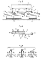
- FIG. 1 shows half of a carriage 1 which is designed as described in EP-A-540 464.
- the car 1 is shown in the direction of arrow I in FIG. Only one of the two parallel tubular rails 20 is shown in FIG.
- the carriage 1 is supported on these rails 20 by rollers 25 and guided by guide rollers 26.
- a guide rail 24 can be attached to the unloading stations above the rollers 25, which prevents tilting when dynamic forces act on the carriage 1.
- a shell carrier 27 is attached to a carriage body 23, on which two shells 16 and 17 are pivotally mounted one behind the other, as seen in the direction of travel.
- two actuating members 38 are attached to the carriage, each actuating member 38 being assigned to each shell 16 and 17, respectively.
- the actuating members 38 each have an actuating lever 40 which is mounted on an axis 28 and on which a push rod 41 is articulated. At the lower end, the push rod 41 is rotatably connected to an arm 43 which is pivotally attached to the body 23.
- An actuating roller 44 is mounted on the side of this arm 43.
- the push rod 41 is taken along and pivots the actuating lever 40 in the direction of the arrow 19.
- the shell 16 or 17 is unlocked and pivoted about the axis 28, a disk 46 striking a rubber buffer 47 .
- two switching elements 6 and 7 are arranged one behind the other as seen in FIG. 3 in the direction of travel. These organs are located at an unloading station, for example at a storage belt 5 according to FIG on a support 15 arranged axis 11 is pivotable.
- the inactive position of the backdrop 10 is indicated with solid lines and the active position with dashed lines.
- a roller 44 runs onto an increasing control cam 10a of the link 10, as is indicated in FIG. 3.
- the actuating roller 44 is thereby lifted up and the arm 43 is pivoted and the push rod 41 articulated on the arm 43 is moved upward.
- the corresponding shell 16 or 17 is thereby unlocked and pivoted.
- the second switching element 6 is split or double and has two links 8 and 9, each of which can be pivoted individually with a pneumatic cylinder 12 or 13 or a similar drive about an axis 11 between an active and an inactive position.
- FIG. 4 shows the backdrop 9 in the active position.
- the actuation roller 44 shown is located at the end of the link 9 in a raised position.
- the link 9 is pivoted in the direction of arrow 21 by means of the pneumatic cylinder 13.
- the backdrop 8 is shown in the inactive position.
- the control cam 8a of the link 8 is located outside the path of the actuating rollers 44.
- the link 8 is pivoted in the direction of arrow 22 by means of the pneumatic cylinder 12.
- the switching element 6 thus consists of two parts 6a and 6b, which can be pivoted independently of one another into an active position with respect to the path of a guide roller 44.
- Figure 5 shows the three different positions of the switching element.
- the two parts 6a and 6b are in the direction of travel seen at a distance from each other arranged one behind the other. If a roller 44 is raised with the front part 6b, the tilting movement is triggered earlier than when the roller 44 is raised by means of the part 6a.
- a part 6a or 6b is preferably arranged so as to be displaceable in the longitudinal direction of the web 2, so that the time of the triggering can be set continuously.
- the two scenes 9 and 10 shown in FIG. 3 are preferably permanently mounted, while the scenery 8 is slidably mounted.
- the distance between the scenes 9 and 10 is thus fixed and set to unload a car 1 with two switches 16 and 17 for delivery of an overly long package 3.
- the two trays 16 and 17 can then be pivoted substantially simultaneously with two scenes 9 and 10 in active positions for unloading. If two individual piece goods are transported on the trays 16 and 17 by the trolley 1, these are preferably unloaded by means of the scenes 8 and 9.
- the 3 lane packets which are lighter in relation to an overly long packet are taken into account. An overly long package can thus be unloaded later according to its narrower discharge path with the scenes 9 and 10.
- all the scenes 8, 9 and 10 are preferably in the inactive position and thus pivoted outwards.
- the path to pivoting the scenes into the active position is very short, which is why switching can be carried out very quickly, which accordingly allows a high conveying speed.
- the load which in each case acts from a roller 44 to be lifted on a link 8, 9 or 10, the corresponding axis 11 and not the corresponding ones Cylinder 12, 13 and 14 loaded.
- At least one of the scenes 8, 9 or 10 is adjustable in its inclination.
- the adjustment can also be carried out, for example, with pneumatic cylinders, not shown here. This makes it possible to adjust the swiveling speed and thus to obtain a particularly gentle or very fast discharge.
Landscapes
- Mechanical Engineering (AREA)
- Engineering & Computer Science (AREA)
- Forklifts And Lifting Vehicles (AREA)
- Specific Conveyance Elements (AREA)
- Rollers For Roller Conveyors For Transfer (AREA)
- Attitude Control For Articles On Conveyors (AREA)
- Discharge Of Articles From Conveyors (AREA)
- Framework For Endless Conveyors (AREA)
- Processing Of Meat And Fish (AREA)
- Threshing Machine Elements (AREA)
- Railway Tracks (AREA)
- Structure Of Belt Conveyors (AREA)
- Branching, Merging, And Special Transfer Between Conveyors (AREA)
- Delivering By Means Of Belts And Rollers (AREA)
Applications Claiming Priority (2)
| Application Number | Priority Date | Filing Date | Title |
|---|---|---|---|
| CH00224/95A CH692661A5 (de) | 1995-01-27 | 1995-01-27 | Fördereinrichtung mit schwenkbaren Lastträgern. |
| CH224/95 | 1995-01-27 |
Publications (2)
| Publication Number | Publication Date |
|---|---|
| EP0723923A1 true EP0723923A1 (fr) | 1996-07-31 |
| EP0723923B1 EP0723923B1 (fr) | 1998-10-28 |
Family
ID=4182121
Family Applications (1)
| Application Number | Title | Priority Date | Filing Date |
|---|---|---|---|
| EP96810041A Revoked EP0723923B1 (fr) | 1995-01-27 | 1996-01-19 | Convoyeur avec porte-charges basculant |
Country Status (10)
| Country | Link |
|---|---|
| US (1) | US5642802A (fr) |
| EP (1) | EP0723923B1 (fr) |
| JP (1) | JPH08244970A (fr) |
| KR (1) | KR0162730B1 (fr) |
| AT (1) | ATE172688T1 (fr) |
| AU (1) | AU704315B2 (fr) |
| CA (1) | CA2167355A1 (fr) |
| CH (1) | CH692661A5 (fr) |
| DE (1) | DE59600720D1 (fr) |
| DK (1) | DK0723923T3 (fr) |
Cited By (1)
| Publication number | Priority date | Publication date | Assignee | Title |
|---|---|---|---|---|
| CN103407780A (zh) * | 2013-08-15 | 2013-11-27 | 伯曼机械制造(上海)有限公司 | 一种分流输送系统 |
Families Citing this family (4)
| Publication number | Priority date | Publication date | Assignee | Title |
|---|---|---|---|---|
| US6607066B1 (en) | 1998-07-10 | 2003-08-19 | Crisplant A/S | Conveyor |
| DE19844478C1 (de) | 1998-09-28 | 2000-08-10 | Siemens Ag | Anordnung und Verfahren zum Sortieren von Stückgut |
| US6367610B1 (en) * | 2000-02-14 | 2002-04-09 | Mantissa Corporation | High efficiency sorting conveyor |
| CN114571845B (zh) * | 2022-03-02 | 2023-12-29 | 深圳市永益鑫包装科技有限公司 | 一种用于绿色环保印刷的热转印装置 |
Citations (3)
| Publication number | Priority date | Publication date | Assignee | Title |
|---|---|---|---|---|
| FR2373464A1 (fr) * | 1976-12-13 | 1978-07-07 | American Chain & Cable Co | Convoyeur du type a plateaux de transport |
| FR2530501A1 (fr) * | 1982-07-22 | 1984-01-27 | Maki Mfg Co Ltd | Dispositif et procede pour trier des objets tels que des fruits et des legumes |
| EP0540464A2 (fr) * | 1991-10-29 | 1993-05-05 | Müller Martini Versand-Systeme Ag | Dispositif de triage de pièces détachées |
Family Cites Families (4)
| Publication number | Priority date | Publication date | Assignee | Title |
|---|---|---|---|---|
| IT1198074B (it) * | 1986-11-10 | 1988-12-21 | Francesco Canziani | Apparecchiatura smistatrice con i dispositivi di trasporto degli oggetti da smistare preposizionabili in funzione della destinazione di scarico |
| CA1316139C (fr) * | 1988-10-31 | 1993-04-13 | Karl Hartlepp | Materiel de tri |
| WO1993015986A1 (fr) * | 1992-02-07 | 1993-08-19 | Siemens Aktiengesellschaft | Dispositif pour transferer des marchandises de detail d'un premier dispositif de transport sur un second |
| US5489017A (en) * | 1993-11-17 | 1996-02-06 | United Parcel Service Of America, Inc. | Tilting tray package sorting apparatus |
-
1995
- 1995-01-27 CH CH00224/95A patent/CH692661A5/de not_active IP Right Cessation
-
1996
- 1996-01-15 AU AU40973/96A patent/AU704315B2/en not_active Ceased
- 1996-01-16 CA CA002167355A patent/CA2167355A1/fr not_active Abandoned
- 1996-01-19 EP EP96810041A patent/EP0723923B1/fr not_active Revoked
- 1996-01-19 DE DE59600720T patent/DE59600720D1/de not_active Revoked
- 1996-01-19 DK DK96810041T patent/DK0723923T3/da active
- 1996-01-19 AT AT96810041T patent/ATE172688T1/de not_active IP Right Cessation
- 1996-01-22 US US08/589,405 patent/US5642802A/en not_active Expired - Fee Related
- 1996-01-25 JP JP8011062A patent/JPH08244970A/ja not_active Withdrawn
- 1996-04-26 KR KR1019960013238A patent/KR0162730B1/ko not_active Expired - Fee Related
Patent Citations (3)
| Publication number | Priority date | Publication date | Assignee | Title |
|---|---|---|---|---|
| FR2373464A1 (fr) * | 1976-12-13 | 1978-07-07 | American Chain & Cable Co | Convoyeur du type a plateaux de transport |
| FR2530501A1 (fr) * | 1982-07-22 | 1984-01-27 | Maki Mfg Co Ltd | Dispositif et procede pour trier des objets tels que des fruits et des legumes |
| EP0540464A2 (fr) * | 1991-10-29 | 1993-05-05 | Müller Martini Versand-Systeme Ag | Dispositif de triage de pièces détachées |
Cited By (1)
| Publication number | Priority date | Publication date | Assignee | Title |
|---|---|---|---|---|
| CN103407780A (zh) * | 2013-08-15 | 2013-11-27 | 伯曼机械制造(上海)有限公司 | 一种分流输送系统 |
Also Published As
| Publication number | Publication date |
|---|---|
| CH692661A5 (de) | 2002-09-13 |
| AU4097396A (en) | 1996-08-08 |
| CA2167355A1 (fr) | 1996-07-28 |
| KR960037284A (ko) | 1996-11-19 |
| KR0162730B1 (ko) | 1999-05-01 |
| EP0723923B1 (fr) | 1998-10-28 |
| DK0723923T3 (da) | 1999-07-12 |
| JPH08244970A (ja) | 1996-09-24 |
| US5642802A (en) | 1997-07-01 |
| ATE172688T1 (de) | 1998-11-15 |
| AU704315B2 (en) | 1999-04-22 |
| DE59600720D1 (de) | 1998-12-03 |
Similar Documents
| Publication | Publication Date | Title |
|---|---|---|
| DE4203799C2 (de) | Anlage zum Verteilen von Stückgütern | |
| EP0540464B1 (fr) | Dispositif de triage de pièces détachées | |
| EP0919495B1 (fr) | Transporteur pour trier des articles | |
| EP0712799B1 (fr) | Transporteur de distribution pour des objets | |
| DE69806474T2 (de) | Förderer mit federndem föderband und hochgeschwindigkeits-entlademöglichkeiten | |
| DE4447396C1 (de) | Sortierförderer mit einer kippbaren Tragschale | |
| EP0059984B1 (fr) | Dispositif de distribution pour un convoyeur | |
| EP0642459A1 (fr) | Dispositif de convoyage suspendu muni d'un dispositif de reception des produits. | |
| DE2921388A1 (de) | Foerdervorrichtung | |
| DE69611740T2 (de) | Vorrichtung zum Sortieren von Produkten | |
| EP0581728B1 (fr) | Chariot d'un convoyeur pour marchandises | |
| DE2415947A1 (de) | Vorrichtung zum entladen von gegenstaenden aus durch eine entladestation gefoerderten behaeltern, insbesondere zum entladen von gepaeck aus fluggepaeckbehaeltern von flugzeugen | |
| EP1115638B1 (fr) | Dispositif de distribution pour articles individuels | |
| EP0727370B1 (fr) | Installation de transport | |
| WO2015028562A1 (fr) | Dispositif de transport | |
| EP0664262A1 (fr) | Elément de transport basculant pour transporteur d'articles (trieuse) | |
| EP0723923B1 (fr) | Convoyeur avec porte-charges basculant | |
| AT400836B (de) | Schüttgutverladewagen | |
| DE19959843A1 (de) | Stückgutförderer | |
| AT410204B (de) | Einrichtung zum vereinzeln und ausschleusen von in einer reihe auf einer rollenbahn abgelegten stückgütern | |
| EP1335871A1 (fr) | Convoyeur de triage avec module de base | |
| DE4341715C1 (de) | Sortierförderer mit einer kippbaren Schale | |
| DE800839C (de) | Gliederfoerderband mit Entladungsmoeglichkeit an einer oder mehreren Stellen | |
| DE4042709C2 (de) | Sortierförderer | |
| DE20004896U1 (de) | Stückgut-Stetigfördereinrichtung |
Legal Events
| Date | Code | Title | Description |
|---|---|---|---|
| PUAI | Public reference made under article 153(3) epc to a published international application that has entered the european phase |
Free format text: ORIGINAL CODE: 0009012 |
|
| AK | Designated contracting states |
Kind code of ref document: A1 Designated state(s): AT BE DE DK FR GB IT NL |
|
| 17P | Request for examination filed |
Effective date: 19961112 |
|
| 17Q | First examination report despatched |
Effective date: 19970522 |
|
| GRAG | Despatch of communication of intention to grant |
Free format text: ORIGINAL CODE: EPIDOS AGRA |
|
| GRAG | Despatch of communication of intention to grant |
Free format text: ORIGINAL CODE: EPIDOS AGRA |
|
| GRAH | Despatch of communication of intention to grant a patent |
Free format text: ORIGINAL CODE: EPIDOS IGRA |
|
| GRAH | Despatch of communication of intention to grant a patent |
Free format text: ORIGINAL CODE: EPIDOS IGRA |
|
| GRAA | (expected) grant |
Free format text: ORIGINAL CODE: 0009210 |
|
| AK | Designated contracting states |
Kind code of ref document: B1 Designated state(s): AT BE DE DK FR GB IT NL |
|
| REF | Corresponds to: |
Ref document number: 172688 Country of ref document: AT Date of ref document: 19981115 Kind code of ref document: T |
|
| REF | Corresponds to: |
Ref document number: 59600720 Country of ref document: DE Date of ref document: 19981203 |
|
| ITF | It: translation for a ep patent filed | ||
| GBT | Gb: translation of ep patent filed (gb section 77(6)(a)/1977) |
Effective date: 19990118 |
|
| ET | Fr: translation filed | ||
| REG | Reference to a national code |
Ref country code: DK Ref legal event code: T3 |
|
| PLBQ | Unpublished change to opponent data |
Free format text: ORIGINAL CODE: EPIDOS OPPO |
|
| PLBI | Opposition filed |
Free format text: ORIGINAL CODE: 0009260 |
|
| PLBQ | Unpublished change to opponent data |
Free format text: ORIGINAL CODE: EPIDOS OPPO |
|
| PLBI | Opposition filed |
Free format text: ORIGINAL CODE: 0009260 |
|
| PLBF | Reply of patent proprietor to notice(s) of opposition |
Free format text: ORIGINAL CODE: EPIDOS OBSO |
|
| 26 | Opposition filed |
Opponent name: BEUMER MASCHINENFABRIK GMBH & CO. KG Effective date: 19990726 |
|
| 26 | Opposition filed |
Opponent name: CRISPLANT A/S Effective date: 19990728 Opponent name: BEUMER MASCHINENFABRIK GMBH & CO. KG Effective date: 19990726 |
|
| NLR1 | Nl: opposition has been filed with the epo |
Opponent name: CRISPLANT A/S Opponent name: BEUMER MASCHINENFABRIK GMBH & CO. KG |
|
| PLBF | Reply of patent proprietor to notice(s) of opposition |
Free format text: ORIGINAL CODE: EPIDOS OBSO |
|
| PLBF | Reply of patent proprietor to notice(s) of opposition |
Free format text: ORIGINAL CODE: EPIDOS OBSO |
|
| REG | Reference to a national code |
Ref country code: GB Ref legal event code: 732E |
|
| RAP2 | Party data changed (patent owner data changed or rights of a patent transferred) |
Owner name: SIEMENS AKTIENGESELLSCHAFT |
|
| REG | Reference to a national code |
Ref country code: FR Ref legal event code: TP |
|
| NLS | Nl: assignments of ep-patents |
Owner name: SIEMENS AKTIENGESELLSCHAFT |
|
| NLT2 | Nl: modifications (of names), taken from the european patent patent bulletin |
Owner name: SIEMENS AKTIENGESELLSCHAFT |
|
| BECA | Be: change of holder's address |
Free format text: 20010412 *SIEMENS A.G.:80333 MUNCHEN |
|
| REG | Reference to a national code |
Ref country code: GB Ref legal event code: IF02 |
|
| PGFP | Annual fee paid to national office [announced via postgrant information from national office to epo] |
Ref country code: NL Payment date: 20030120 Year of fee payment: 8 |
|
| PGFP | Annual fee paid to national office [announced via postgrant information from national office to epo] |
Ref country code: AT Payment date: 20031229 Year of fee payment: 9 |
|
| PGFP | Annual fee paid to national office [announced via postgrant information from national office to epo] |
Ref country code: GB Payment date: 20040113 Year of fee payment: 9 |
|
| RDAF | Communication despatched that patent is revoked |
Free format text: ORIGINAL CODE: EPIDOSNREV1 |
|
| PGFP | Annual fee paid to national office [announced via postgrant information from national office to epo] |
Ref country code: DK Payment date: 20040114 Year of fee payment: 9 |
|
| PGFP | Annual fee paid to national office [announced via postgrant information from national office to epo] |
Ref country code: BE Payment date: 20040120 Year of fee payment: 9 |
|
| PGFP | Annual fee paid to national office [announced via postgrant information from national office to epo] |
Ref country code: FR Payment date: 20040123 Year of fee payment: 9 |
|
| PGFP | Annual fee paid to national office [announced via postgrant information from national office to epo] |
Ref country code: DE Payment date: 20040322 Year of fee payment: 9 |
|
| RDAG | Patent revoked |
Free format text: ORIGINAL CODE: 0009271 |
|
| STAA | Information on the status of an ep patent application or granted ep patent |
Free format text: STATUS: PATENT REVOKED |
|
| 27W | Patent revoked |
Effective date: 20040124 |
|
| GBPR | Gb: patent revoked under art. 102 of the ep convention designating the uk as contracting state |
Free format text: 20040124 |
|
| NLR2 | Nl: decision of opposition |
Effective date: 20040124 |
|
| PGFP | Annual fee paid to national office [announced via postgrant information from national office to epo] |
Ref country code: IT Payment date: 20060131 Year of fee payment: 11 |