EP0724041A1 - Robinet pour applications sanitaires avec des éléments de décoration interchangeables - Google Patents
Robinet pour applications sanitaires avec des éléments de décoration interchangeables Download PDFInfo
- Publication number
- EP0724041A1 EP0724041A1 EP95203628A EP95203628A EP0724041A1 EP 0724041 A1 EP0724041 A1 EP 0724041A1 EP 95203628 A EP95203628 A EP 95203628A EP 95203628 A EP95203628 A EP 95203628A EP 0724041 A1 EP0724041 A1 EP 0724041A1
- Authority
- EP
- European Patent Office
- Prior art keywords
- tap
- hydraulic unit
- shells
- cover elements
- elements
- Prior art date
- Legal status (The legal status is an assumption and is not a legal conclusion. Google has not performed a legal analysis and makes no representation as to the accuracy of the status listed.)
- Withdrawn
Links
- XLYOFNOQVPJJNP-UHFFFAOYSA-N water Substances O XLYOFNOQVPJJNP-UHFFFAOYSA-N 0.000 claims abstract description 17
- 229920002994 synthetic fiber Polymers 0.000 claims description 3
- 239000002184 metal Substances 0.000 description 3
- 230000000295 complement effect Effects 0.000 description 2
- 230000000630 rising effect Effects 0.000 description 2
- 210000005069 ears Anatomy 0.000 description 1
- 238000003780 insertion Methods 0.000 description 1
- 230000037431 insertion Effects 0.000 description 1
- 230000013011 mating Effects 0.000 description 1
- 238000012986 modification Methods 0.000 description 1
- 230000004048 modification Effects 0.000 description 1
- 239000002699 waste material Substances 0.000 description 1
Images


Classifications
-
- E—FIXED CONSTRUCTIONS
- E03—WATER SUPPLY; SEWERAGE
- E03C—DOMESTIC PLUMBING INSTALLATIONS FOR FRESH WATER OR WASTE WATER; SINKS
- E03C1/00—Domestic plumbing installations for fresh water or waste water; Sinks
- E03C1/02—Plumbing installations for fresh water
- E03C1/04—Water-basin installations specially adapted to wash-basins or baths
- E03C1/0404—Constructional or functional features of the spout
-
- E—FIXED CONSTRUCTIONS
- E03—WATER SUPPLY; SEWERAGE
- E03C—DOMESTIC PLUMBING INSTALLATIONS FOR FRESH WATER OR WASTE WATER; SINKS
- E03C1/00—Domestic plumbing installations for fresh water or waste water; Sinks
- E03C1/02—Plumbing installations for fresh water
- E03C1/04—Water-basin installations specially adapted to wash-basins or baths
Definitions
- This invention relates to taps for sanitary appliances.
- the ornamental function is performed by the actual functional hydraulic unit of the tap, ie mainly by that metal body of it which comprises the water exit mouth and the valve means for its adjustment (flow rate and hot and cold water mixing).
- Said metal body is shaped, machined and treated externally to define, together with the handle (or handles) of the adjustment means, the appearance of the tap.
- the present invention provides a tap with an externally surface-unfinished hydraulic unit of standard shape comprising the water adjustment means and the delivery mouth, which performs only the technical function.
- the appearance of the tap is instead determined by cover elements in the form of shells, particularly of synthetic material, which are positioned to cover all or part of the hydraulic unit to define the tap appearance.
- cover elements are positioned on the hydraulic unit by means of form elements acting as locators, and are fixed to it by simple connection means, such as screws or by simple insertion.
- the manufacturer or seller need therefore stock only a single hydraulic unit model (which as stated represents the most costly component) together with various cover elements (of relatively low cost) to be able to offer different tap models. Moreover, the user wishing to change the appearance of his tap can retain the same hydraulic unit and merely change the cover elements.
- the tap comprises a hydraulic unit, indicated overall by 10, which performs only the technical function of the tap, ie it serves for delivering, and for adjusting the flow rate and mixing of, hot water and cold water.
- a hydraulic unit indicated overall by 10 which performs only the technical function of the tap, ie it serves for delivering, and for adjusting the flow rate and mixing of, hot water and cold water.
- the hydraulic unit is shown schematically in external view.
- the unit 10 comprises a usual delivery conduit 12 having an exit mouth 11.
- the conduit 12 extends from a usual valve body 13 which is connected to the domestic water system feeding hot/cold water and internally contains usual water adjustment means, ie means for mixing hot and cold water and means for adjusting the flow rate from the mouth 11.
- the tap illustrated in Figures 4-6 comprises a usual second water exit mouth 14 to be connected to a floating shower hose (not shown).
- a usual change-over valve 15 for feeding the water either to the mouth 11 or to the mouth 14.
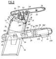
- cover elements in the form of rigid shells, in particular of synthetic material (such as ABS) arranged to at least partly cover the unit 10 and to define the tap appearance.
- cover elements are provided formed from several shells which can be fitted together, these covering the stem 16 and being fixed to it, and moreover defining an internally hollow body forming the handle for moving said stem 16.
- a substantially flat shell 21 with its concavity facing upwards and having a lower tubular appendix 21' which mates with the stem 16 and is fixed to it by a screw 31.
- a tubular shell 23 fixed below the shell 21 to surround the appendix 21' and cover it from view.
- the shell 23 is fixed to the lower surface of the shell 21 by screws 34, the head of which remains enclosed between the shells 21, 22.
- the upper part of the body 13 is covered with a thin cylindrical tubular shell 24, the upper edge 24' of which is bent inwards and rests against the edge of the upper surface 13' of the body 13.
- the shell 24 is fixed to the body 13 by screws 242 inserted axially into the body 13, their heads engaging small ears 241 branching from the upper edge 24'.
- a further shell 25 positioned within the shell 23 to surround the top of the body 13 and cover it from view.
- the shell 25 possesses small snap-hooks 35 which engage the edge 24' of the shell 24.
- the lower part 13'' of the lateral surface of the body 13 is exposed and is suitably machined/treated to assume the required appearance.
- the delivery conduit 12 is covered by an upper shell 26 and a lower shell 27, these being complementary and being fitted together.
- the lower shell 27 possesses a hole 272 through which the exit mouth 11 can pass.
- the shells 26 and 27 also possess respective through holes 260 and 270 through which the shell 24 and the lower part 13'' of the body 13 pass.
- the two shells 26 and 27 mate along their respective edges, which are of stepped cross-section to allow them to be fitted together. They are joined together by screws 36, each of which has a head which sits in a seat provided in the lower shell 27 and a shank which engages in a hole provided in a projection 261 projecting downwards from the inner surface of the shell 26.
- Correct positioning of the shells 26 and 27 on the hydraulic unit is determined by form elements provided on the shells to locate corresponding parts of the hydraulic unit.
- the edges of the two holes 270 and 260 are shaped to mate with the lateral surface of the body 13 and of the shell 24 respectively.
- the tap can also comprise a control lever for the device which closes the wash-basin/bidet discharge device (pop-up waste fitting).
- This lever passes through the rear part of the shells 26 and 27 and the lower part of the body 13.
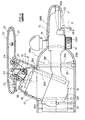
- the body 13 the conduit 12 and the valve 15 are enclosed and covered by two casings A and B each composed of an upper shell 28A and 28B respectively and a lower shell 29A and 29B respectively, which are complementary and are assembled together along a horizontal central joining plane.
- Said casing A is rounded at its front and encloses the body 13.
- the casing B is positioned to the side of the casing A and is of lesser height than this, to enclose the conduit 12.
- the two shells 28A and 29A and the two shells 28B and 29B mate along their respective edges, which are of stepped cross-section to enable them to be fitted together. Said shells are also joined together by screws 37, each of which passes through an element 291 projecting from the inner surface of the upper shell 28.
- the lower shell 29B possesses a hole 292 and a hole 294 through which the exit mouth 11 and the second mouth 14 pass.
- Correct positioning of the shells 28A, 28B and 29A, 29B is determined by form elements provided on the shells to locate corresponding parts of the hydraulic unit. Specifically, from the inner surface of the lower shell 29B there projects a rising edge 293 of stepped cross-section positioned about the hole 292 to mate with a corresponding stepped edge 112 provided on the lateral surface of the mouth 11. The edge of the hole 294, mating with the lateral surface of the mouth 14, also acts as a locator element.
- the upper shell 28A possesses a hole 282 which substantially mates with the lower base of the body 13 to act as a locator element.
- the upper edge of the shell 28A is bent inwards about the hole 282 and to it there is joined a further shell 30 positioned internal to the shell 23, to surround the top of the body 13 and cover it from view.
- This shell 30 possesses small snap-hooks 38 which engage the edge of the hole 282.
- All the described shells are interchangeable with other identical shells, or shells of different colour/finish/appearance. This is of particular value in the case of the shells forming the tap handle and those covering the tap delivery mouth.
Landscapes
- Health & Medical Sciences (AREA)
- Life Sciences & Earth Sciences (AREA)
- Engineering & Computer Science (AREA)
- Hydrology & Water Resources (AREA)
- Public Health (AREA)
- Water Supply & Treatment (AREA)
- Domestic Plumbing Installations (AREA)
- Compositions Of Oxide Ceramics (AREA)
- Bidet-Like Cleaning Device And Other Flush Toilet Accessories (AREA)
- Apparatus For Disinfection Or Sterilisation (AREA)
Applications Claiming Priority (2)
| Application Number | Priority Date | Filing Date | Title |
|---|---|---|---|
| ITRE950003U | 1995-01-24 | ||
| IT95RE000003 IT239214Y1 (it) | 1995-01-24 | 1995-01-24 | Rubinetto per apparecchi sanitari, con elementi esteticiintercambiabili |
Publications (1)
| Publication Number | Publication Date |
|---|---|
| EP0724041A1 true EP0724041A1 (fr) | 1996-07-31 |
Family
ID=11398691
Family Applications (1)
| Application Number | Title | Priority Date | Filing Date |
|---|---|---|---|
| EP95203628A Withdrawn EP0724041A1 (fr) | 1995-01-24 | 1995-12-27 | Robinet pour applications sanitaires avec des éléments de décoration interchangeables |
Country Status (4)
| Country | Link |
|---|---|
| EP (1) | EP0724041A1 (fr) |
| CN (1) | CN2262635Y (fr) |
| CA (1) | CA2167773A1 (fr) |
| IT (1) | IT239214Y1 (fr) |
Cited By (4)
| Publication number | Priority date | Publication date | Assignee | Title |
|---|---|---|---|---|
| EP0866180A3 (fr) * | 1997-03-19 | 2000-03-01 | Inax Corporation | Dispositif de fixation d'un robinet |
| EP1018579A2 (fr) | 1999-01-09 | 2000-07-12 | Hansgrohe AG | Pomme de douche |
| CN104619926A (zh) * | 2012-06-29 | 2015-05-13 | 勒斯水龙头普尔斯透公司 | 电子水龙头的模块化结构 |
| JP2019100017A (ja) * | 2017-11-29 | 2019-06-24 | パナソニックIpマネジメント株式会社 | 水栓 |
Families Citing this family (1)
| Publication number | Priority date | Publication date | Assignee | Title |
|---|---|---|---|---|
| CN103291967A (zh) * | 2013-05-10 | 2013-09-11 | 深圳市奥力原环境科技有限公司 | 水龙头 |
Citations (4)
| Publication number | Priority date | Publication date | Assignee | Title |
|---|---|---|---|---|
| EP0307105A1 (fr) * | 1987-09-09 | 1989-03-15 | Armitage Shanks Limited | Soupapes pour adduction d'eau |
| DE4018503A1 (de) * | 1989-06-20 | 1991-01-10 | Sol Spa | Hahn fuer waschbecken, spuelbecken o.dgl. |
| EP0485346A1 (fr) * | 1990-11-09 | 1992-05-13 | Solid Plast S.R.L. | Bâti composite pour robinets |
| EP0632220A2 (fr) * | 1993-06-30 | 1995-01-04 | Solid Plast S.R.L. | Boîte composée pour robinets d'eau |
-
1995
- 1995-01-24 IT IT95RE000003 patent/IT239214Y1/it active
- 1995-12-27 EP EP95203628A patent/EP0724041A1/fr not_active Withdrawn
-
1996
- 1996-01-22 CA CA 2167773 patent/CA2167773A1/fr not_active Abandoned
- 1996-01-24 CN CN96202302U patent/CN2262635Y/zh not_active Expired - Fee Related
Patent Citations (4)
| Publication number | Priority date | Publication date | Assignee | Title |
|---|---|---|---|---|
| EP0307105A1 (fr) * | 1987-09-09 | 1989-03-15 | Armitage Shanks Limited | Soupapes pour adduction d'eau |
| DE4018503A1 (de) * | 1989-06-20 | 1991-01-10 | Sol Spa | Hahn fuer waschbecken, spuelbecken o.dgl. |
| EP0485346A1 (fr) * | 1990-11-09 | 1992-05-13 | Solid Plast S.R.L. | Bâti composite pour robinets |
| EP0632220A2 (fr) * | 1993-06-30 | 1995-01-04 | Solid Plast S.R.L. | Boîte composée pour robinets d'eau |
Cited By (7)
| Publication number | Priority date | Publication date | Assignee | Title |
|---|---|---|---|---|
| EP0866180A3 (fr) * | 1997-03-19 | 2000-03-01 | Inax Corporation | Dispositif de fixation d'un robinet |
| EP1357233A1 (fr) * | 1997-03-19 | 2003-10-29 | Inax Corporation | Dispositif de fixation d'un robinet |
| EP1018579A2 (fr) | 1999-01-09 | 2000-07-12 | Hansgrohe AG | Pomme de douche |
| EP1018579A3 (fr) * | 1999-01-09 | 2001-04-18 | Hansgrohe AG | Pomme de douche |
| CN104619926A (zh) * | 2012-06-29 | 2015-05-13 | 勒斯水龙头普尔斯透公司 | 电子水龙头的模块化结构 |
| JP2019100017A (ja) * | 2017-11-29 | 2019-06-24 | パナソニックIpマネジメント株式会社 | 水栓 |
| CN110005023B (zh) * | 2017-11-29 | 2021-12-14 | 松下知识产权经营株式会社 | 水龙头 |
Also Published As
| Publication number | Publication date |
|---|---|
| CA2167773A1 (fr) | 1996-07-25 |
| IT239214Y1 (it) | 2001-02-26 |
| CN2262635Y (zh) | 1997-09-17 |
| ITRE950003U1 (it) | 1996-07-24 |
Similar Documents
| Publication | Publication Date | Title |
|---|---|---|
| US5803120A (en) | Faucets for sanitary fixtures with interchangeable decorative elements | |
| US5819335A (en) | Washing facility | |
| US7314189B2 (en) | Delivery system for treated water, showerhead and supply pipe for said system | |
| US20080196159A1 (en) | Method and apparatus for soft-feel plumbing fixtures | |
| US5720055A (en) | Cleaning and hygienic device | |
| US2997058A (en) | Plumbing fixture | |
| TWD103999S1 (zh) | 盥洗用水龍頭 | |
| CA1110802A (fr) | Cabinet d'aisances et bidet combines | |
| NZ532493A (en) | Washing platform with a raised central work surface surrounded by a trough | |
| AU2004271957B2 (en) | Lavatory with a removable washing platform | |
| JP3635652B2 (ja) | 水槽付き家具 | |
| CA2167773A1 (fr) | Robinets pour appareils sanitaires, a elements decoratifs interchangeables | |
| EP3981924A1 (fr) | Dispositif de sortie d'eau | |
| AU2020100512A4 (en) | In-bath water filler and overflow arrangement | |
| JP3174766B2 (ja) | ガス栓一体型水栓 | |
| CN212251299U (zh) | 分配装置 | |
| GR1004827B (el) | Κρουνος δια νεροχυτες κουζινας με μια οπη | |
| DE59500904D1 (de) | Duschtassenauslauf mit Schmutzfangsieb | |
| JPH1182793A (ja) | 湯水混合水栓 | |
| JP7408054B2 (ja) | 水まわり機能集約ユニット | |
| GB2315282A (en) | Bidet fitting for a toilet | |
| AU741699B2 (en) | A cistern inlet valve arrangement | |
| KR200307063Y1 (ko) | 냉온수 혼합 수도밸브 | |
| CA2228857A1 (fr) | Fixation de robinet de type bidet | |
| GB2354305A (en) | Control valve assembly outlet arrangement |
Legal Events
| Date | Code | Title | Description |
|---|---|---|---|
| PUAI | Public reference made under article 153(3) epc to a published international application that has entered the european phase |
Free format text: ORIGINAL CODE: 0009012 |
|
| AK | Designated contracting states |
Kind code of ref document: A1 Designated state(s): AT BE DE ES FR GB IT LU NL PT |
|
| STAA | Information on the status of an ep patent application or granted ep patent |
Free format text: STATUS: THE APPLICATION IS DEEMED TO BE WITHDRAWN |
|
| 18D | Application deemed to be withdrawn |
Effective date: 19970203 |