EP0724043A1 - Unité de commande pour une armature sanitaire - Google Patents
Unité de commande pour une armature sanitaire Download PDFInfo
- Publication number
- EP0724043A1 EP0724043A1 EP96100724A EP96100724A EP0724043A1 EP 0724043 A1 EP0724043 A1 EP 0724043A1 EP 96100724 A EP96100724 A EP 96100724A EP 96100724 A EP96100724 A EP 96100724A EP 0724043 A1 EP0724043 A1 EP 0724043A1
- Authority
- EP
- European Patent Office
- Prior art keywords
- control
- energy
- evaluation electronics
- saving mode
- mode
- Prior art date
- Legal status (The legal status is an assumption and is not a legal conclusion. Google has not performed a legal analysis and makes no representation as to the accuracy of the status listed.)
- Granted
Links
- 238000011156 evaluation Methods 0.000 claims abstract description 36
- 238000001514 detection method Methods 0.000 claims abstract description 18
- XLYOFNOQVPJJNP-UHFFFAOYSA-N water Substances O XLYOFNOQVPJJNP-UHFFFAOYSA-N 0.000 claims description 15
- 230000005855 radiation Effects 0.000 claims description 9
- 238000004806 packaging method and process Methods 0.000 claims description 5
- 238000010276 construction Methods 0.000 claims description 3
- 238000000034 method Methods 0.000 claims description 3
- 238000012544 monitoring process Methods 0.000 claims description 3
- 230000000694 effects Effects 0.000 claims description 2
- 238000013100 final test Methods 0.000 claims description 2
- 230000000712 assembly Effects 0.000 claims 1
- 238000000429 assembly Methods 0.000 claims 1
- 230000004913 activation Effects 0.000 description 9
- 230000005540 biological transmission Effects 0.000 description 3
- 238000009434 installation Methods 0.000 description 3
- 239000000463 material Substances 0.000 description 3
- 230000001960 triggered effect Effects 0.000 description 3
- 230000035945 sensitivity Effects 0.000 description 2
- 238000012360 testing method Methods 0.000 description 2
- 230000009849 deactivation Effects 0.000 description 1
- 230000006735 deficit Effects 0.000 description 1
- 238000010586 diagram Methods 0.000 description 1
- 238000003780 insertion Methods 0.000 description 1
- 230000037431 insertion Effects 0.000 description 1
- 230000007774 longterm Effects 0.000 description 1
- 230000002093 peripheral effect Effects 0.000 description 1
- 230000002035 prolonged effect Effects 0.000 description 1
- 230000007420 reactivation Effects 0.000 description 1
- 230000009467 reduction Effects 0.000 description 1
- 238000007789 sealing Methods 0.000 description 1
- 238000012549 training Methods 0.000 description 1
Images

Classifications
-
- E—FIXED CONSTRUCTIONS
- E03—WATER SUPPLY; SEWERAGE
- E03C—DOMESTIC PLUMBING INSTALLATIONS FOR FRESH WATER OR WASTE WATER; SINKS
- E03C1/00—Domestic plumbing installations for fresh water or waste water; Sinks
- E03C1/02—Plumbing installations for fresh water
- E03C1/05—Arrangements of devices on wash-basins, baths, sinks, or the like for remote control of taps
- E03C1/055—Electrical control devices, e.g. with push buttons, control panels or the like
- E03C1/057—Electrical control devices, e.g. with push buttons, control panels or the like touchless, i.e. using sensors
Definitions
- the invention relates to a control device for a sanitary fitting, in particular a water outlet control, with a detection device containing at least one transmitter and a receiver, preferably working with infrared light radiation, control and evaluation electronics and one or more batteries or accumulators for the electrical energy supply.
- a control device for a sanitary fitting, in particular a water outlet control, with a detection device containing at least one transmitter and a receiver, preferably working with infrared light radiation, control and evaluation electronics and one or more batteries or accumulators for the electrical energy supply.
- control devices are mostly used for water outlet fittings on washstands, urinals etc.
- One or more primary cells with a defined minimum capacity and a limited, also system-related shelf life are used for energy supply in these battery-operated, non-contact controlled sanitary fittings.
- the invention has for its object to provide an improved control device in which the consumption of electrical energy can be significantly reduced. It is part of the task to propose a simple and safe method for installing and operating the control device in a sanitary fitting.
- a solenoid valve 4 with a water inlet 41 and a water outlet 42 is provided.
- the solenoid valve 4 can be controlled by control and evaluation electronics 1.
- a detection device 2 is provided in the area of the water outlet 42, with which the presence of a user can be determined.
- a transmitter 21 emits a clocked infrared light beam, which is reflected by a receiver 22 after being reflected on an object in the predetermined detection range.
- the detection device When the presence of a user is ascertained, the detection device generates a signal which is output to the control and evaluation electronics 1, in which a corresponding water outlet program is then processed via a microprocessor or microcontroller, the magnetic valve 4 in the water outlet fitting being after a predetermined period of time ( Delay time) an opening pulse and a closing pulse is supplied after a likewise predetermined opening period.
- the electrical power supply to the control and evaluation electronics 1 with the detection device 2 and the solenoid valve 4 is provided by a battery 3, the control and evaluation electronics 1, the detection device 2, which Battery 3 and the solenoid valve 4 are integrated in the water outlet fitting.
- the system software of the control and evaluation electronics 1 is expanded with an energy-saving mode in which the program execution normally executed is interrupted and all peripheral consumers, in particular the particularly energy-intensive transmission of infrared light , with the exception of the receiver 22 for infrared light radiation, the sensitivity of which is advantageously increased by appropriate circuitry.
- the software for the energy-saving mode (sleep mode) is stored in a module 11.
- the microcontroller unit or microprocessor unit provided in the control and evaluation electronics 1 is itself switched to a stand-by mode (STOP mode, POWER DOWN mode), which reduces the current consumption, for example, to 0.3 to 1.0 microamps or approximately minimized one hundredth of the current consumption in normal operation.
- STOP mode POWER DOWN mode
- the output signal of the receiver 22 is connected directly or via a suitable amplifier / filter circuit to an input (interrupt input) of the control and evaluation electronics 1.
- the energy saving mode (sleep mode) of the water outlet fitting is preset by the manufacturer using a suitable tool, e.g. programming device, remote control, etc.
- the module 11 is present in the software of the control and evaluation electronics 1 or of the microcontroller, which is activated by the mentioned aids, after a defined delay time of, for example, 60 seconds Targeted "powerdown" of the control and evaluation electronics 1 or the microcontroller in "sleep mode" is carried out.
- the control and evaluation electronics 1 or the controller then ceases all activities, except for monitoring the interrupt input (microcontroller port) of the receiver 22.
- a sticker 23 is issued during the delay time infrared-opaque material on the detection device 2, in particular on the receiver 22 attached.
- the normal mode of the control and evaluation electronics 1 is reactivated by the detector 22 detecting infrared light radiation that exceeds a limit level value, as a result of which an interrupt is triggered at the microcontroller port.
- the control and evaluation electronics 1 can therefore be switched from the energy-saving mode to the normal operating mode by removing the sticker 23, i.e. Sending infrared light pulses and presence detection with appropriate circuits of the solenoid valve 4.
- the increased sensitivity of the receiver is advantageous in that the infrared light background radiation contained in normal daylight is sufficient in terms of intensity to switch from the energy-saving mode to the normal operating mode.
- the activation of the normal operating mode can be triggered by any type of infrared light radiation with a relevant wavelength range, such as incandescent light, candle light or by rubbing a match, etc.
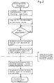
- the control and evaluation electronics 1 can be in the following To be installed and operated in a sanitary fitting: At the factory, the solenoid valve 4, the detection device 2, the control and evaluation electronics 1 and the battery 3 are first installed in a sanitary fitting housing provided with a water inlet 41 and a water outlet 42 during the final assembly. The sanitary fitting is then subjected to a final test.
- the energy-saving mode (sleep mode) in the control and evaluation electronics 1 is first activated with a hand-held transmitter (IR remote control), the receiver 22 then being present in a predetermined, but in principle freely selectable delay time of, for example, 60 seconds the sticker 23 made of infrared-opaque material can be covered and / or the fitting can be packaged in a packaging made of infrared-opaque material, after which storage and / or transportation with distribution of the sanitary fitting can follow over a relatively long period of time.
- IR remote control IR remote control
- the packaging and / or the sticker 23 are removed from the detection device 2, so that now when the receiver 22 detects a sufficient infrared light level (intensity) (via microcontroller interrupt), the energy-saving mode (sleep mode) the control and evaluation electronics 1 is deactivated and the normal operating mode is activated.
- the sanitary fitting is now ready for normal operation.
- the installer / user therefore requires no or only generally available aids to activate an automatic sanitary fitting delivered in energy-saving mode (sleep mode) or to switch it to normal operating mode.
- a once activated energy-saving mode (sleep mode) is also taken up again after removal and reinsertion of the battery 3 after an activation delay has expired.
- a "POWER ON RESET" of the control and evaluation electronics 1 leads the device back into the energy-saving mode (sleep mode), as long as a microcontroller interrupt is not triggered by the reception of an adequate infrared light intensity.
- the energy saving mode can be activated and deactivated as often as required. This makes it possible to demonstrate the function for training courses, exhibitions, etc.
- the subsequent activation of the energy-saving mode (sleep mode) can be useful if the capacity of the installed battery is to be spared for the period of prolonged non-use of the valve.
- control and evaluation electronics can also be designed such that, for example, level-selective by evaluating the intensity of the received signal, which is caused by reflection of the infrared light transmission signal on a reflector, as described, for example, in German patent application P 44 20 335.7 is specified, is received by the receiver 22, the activation of the energy saving mode takes place.
- the control and evaluation electronics according to the invention can also provide for the activation of the energy-saving mode when the infrared light intensity in the receiver caused by the transmission signal exceeds a defined level for a certain period of time t.
- control and evaluation electronics can be designed in such a way that it provides for an automatic activation or deactivation of the energy-saving mode even by evaluating the current ambient infrared light radiation. Monitoring of the infrared light surrounding radiation can thus be used to identify phases of non-use, such as night operation or darkness, etc., with automatic activation of the energy-saving mode or a reactivation of the normal operating mode.
Landscapes
- Health & Medical Sciences (AREA)
- Life Sciences & Earth Sciences (AREA)
- Engineering & Computer Science (AREA)
- Hydrology & Water Resources (AREA)
- Public Health (AREA)
- Water Supply & Treatment (AREA)
- Domestic Plumbing Installations (AREA)
- Confectionery (AREA)
- Selective Calling Equipment (AREA)
- Sanitary Device For Flush Toilet (AREA)
- Manipulator (AREA)
- Lining Or Joining Of Plastics Or The Like (AREA)
- Massaging Devices (AREA)
- Valve Device For Special Equipments (AREA)
Applications Claiming Priority (2)
| Application Number | Priority Date | Filing Date | Title |
|---|---|---|---|
| DE19502214A DE19502214A1 (de) | 1995-01-25 | 1995-01-25 | Steuereinrichtung für eine Sanitärarmatur |
| DE19502214 | 1995-01-25 |
Publications (2)
| Publication Number | Publication Date |
|---|---|
| EP0724043A1 true EP0724043A1 (fr) | 1996-07-31 |
| EP0724043B1 EP0724043B1 (fr) | 2002-06-05 |
Family
ID=7752275
Family Applications (1)
| Application Number | Title | Priority Date | Filing Date |
|---|---|---|---|
| EP96100724A Expired - Lifetime EP0724043B1 (fr) | 1995-01-25 | 1996-01-19 | Unité de commande pour une armature sanitaire |
Country Status (7)
| Country | Link |
|---|---|
| US (1) | US5743511A (fr) |
| EP (1) | EP0724043B1 (fr) |
| JP (1) | JPH08218459A (fr) |
| AT (1) | ATE218656T1 (fr) |
| DE (2) | DE19502214A1 (fr) |
| DK (1) | DK0724043T3 (fr) |
| ES (1) | ES2177685T3 (fr) |
Cited By (1)
| Publication number | Priority date | Publication date | Assignee | Title |
|---|---|---|---|---|
| CN101949163A (zh) * | 2010-08-25 | 2011-01-19 | 南京航空航天大学 | 公用水池智能节水系统 |
Families Citing this family (28)
| Publication number | Priority date | Publication date | Assignee | Title |
|---|---|---|---|---|
| US5915417A (en) * | 1997-09-15 | 1999-06-29 | T&S Brass And Bronze Works, Inc. | Automatic fluid flow control apparatus |
| DE10029230A1 (de) * | 2000-06-14 | 2001-12-20 | Kludi Armaturen Scheffer Vertr | Wasserarmatur |
| DE10042165C1 (de) * | 2000-08-17 | 2002-04-18 | Butzke Werke Aqua | System zur Steuerung und Überwachung von Sanitärarmaturen |
| US7690395B2 (en) | 2004-01-12 | 2010-04-06 | Masco Corporation Of Indiana | Multi-mode hands free automatic faucet |
| AT501971B1 (de) * | 2004-12-01 | 2007-07-15 | Herbert Wimberger | Sensorvorrichtung |
| DE102005040235B4 (de) * | 2005-08-24 | 2021-05-27 | GROHEDAL Sanitärsysteme GmbH | Steuereinrichtung für eine Sanitärarmatur |
| DE102005040763B4 (de) * | 2005-08-26 | 2022-02-10 | Cedes Ag | Türsensoranordnung |
| US7867172B1 (en) | 2006-11-09 | 2011-01-11 | Dingane Baruti | Combination toothbrush and peak flow meter system |
| US8438672B2 (en) | 2005-11-11 | 2013-05-14 | Masco Corporation Of Indiana | Integrated electronic shower system |
| US9243392B2 (en) | 2006-12-19 | 2016-01-26 | Delta Faucet Company | Resistive coupling for an automatic faucet |
| CA2676976C (fr) | 2007-01-31 | 2015-10-06 | Masco Corporation Of Indiana | Appareil et procede de detection capacitive pour des robinets |
| US7806141B2 (en) | 2007-01-31 | 2010-10-05 | Masco Corporation Of Indiana | Mixing valve including a molded waterway assembly |
| DE102007011183B4 (de) * | 2007-03-06 | 2014-04-17 | Aquis Sanitär AG | Elektrisch betätigbare Sanitäraramtur |
| WO2008118402A1 (fr) | 2007-03-28 | 2008-10-02 | Masco Corporation Of Indiana | Capteur tactile capacitif amélioré |
| GB2467661B (en) | 2007-09-20 | 2013-02-13 | Bradley Fixtures Corp | Lavatory system |
| MX2010006473A (es) | 2007-12-11 | 2010-09-22 | Masco Corp | Disposicion de acoplamiento capacitivo para un grifo. |
| WO2011044247A1 (fr) | 2009-10-07 | 2011-04-14 | Bradley Fixtures Corporation | Système de lavabo avec sèche-mains |
| US8561626B2 (en) | 2010-04-20 | 2013-10-22 | Masco Corporation Of Indiana | Capacitive sensing system and method for operating a faucet |
| US8776817B2 (en) | 2010-04-20 | 2014-07-15 | Masco Corporation Of Indiana | Electronic faucet with a capacitive sensing system and a method therefor |
| JP2012072619A (ja) * | 2010-09-29 | 2012-04-12 | Toto Ltd | 水栓装置 |
| US9267736B2 (en) | 2011-04-18 | 2016-02-23 | Bradley Fixtures Corporation | Hand dryer with point of ingress dependent air delay and filter sensor |
| US9170148B2 (en) | 2011-04-18 | 2015-10-27 | Bradley Fixtures Corporation | Soap dispenser having fluid level sensor |
| EP2823107A4 (fr) | 2012-03-07 | 2016-06-15 | Moen Inc | Raccord d'équipement de plomberie électronique |
| CA2873015C (fr) | 2012-03-21 | 2018-11-13 | Bradley Fixtures Corporation | Systeme de bassine et de sechage des mains |
| US10100501B2 (en) | 2012-08-24 | 2018-10-16 | Bradley Fixtures Corporation | Multi-purpose hand washing station |
| US10041236B2 (en) | 2016-06-08 | 2018-08-07 | Bradley Corporation | Multi-function fixture for a lavatory system |
| US11015329B2 (en) | 2016-06-08 | 2021-05-25 | Bradley Corporation | Lavatory drain system |
| DE102016120016A1 (de) * | 2016-10-20 | 2018-04-26 | Aquis Sanitär AG | Überwachungsvorrichtung für eine sanitäre Anlage |
Citations (6)
| Publication number | Priority date | Publication date | Assignee | Title |
|---|---|---|---|---|
| EP0313162A2 (fr) * | 1987-10-23 | 1989-04-26 | Philips Patentverwaltung GmbH | Procédé de commande et de télécommande d'un appareil commutable avec alimentation à piles, mis en- ou hors-fonction par l'approche ou l'éloignement d'un utilisateur |
| DE3843047A1 (de) * | 1987-12-23 | 1989-07-13 | Coyne & Delany Co | Einrichtung zum regeln des zulaufes von wasser |
| NL8802707A (nl) * | 1988-11-03 | 1990-06-01 | Melker B V De | Besturingsstelsel voor watertoevoer aan een watertappunt met behulp van infrarode lichaamswarmtedetectie. |
| EP0501262A1 (fr) * | 1991-03-01 | 1992-09-02 | Hansa Metallwerke Ag | Robinetterie commandée à proximité |
| DE4218658A1 (de) * | 1991-06-19 | 1992-12-24 | Sloan Valve Co | Batteriebetriebene sensor- und kontrollschaltung |
| DE29500918U1 (de) * | 1994-02-02 | 1995-03-16 | Geberit Technik Ag, Jona | Anordnung zur berührungslosen Betätigung des Wasserflusses einer Sanitäranlage |
Family Cites Families (2)
| Publication number | Priority date | Publication date | Assignee | Title |
|---|---|---|---|---|
| US5086526A (en) * | 1989-10-10 | 1992-02-11 | International Sanitary Ware Manufacturin Cy, S.A. | Body heat responsive control apparatus |
| DE4420335A1 (de) * | 1994-06-10 | 1995-12-14 | Grohe Armaturen Friedrich | Wasserarmaturensteuerung |
-
1995
- 1995-01-25 DE DE19502214A patent/DE19502214A1/de not_active Ceased
- 1995-11-16 JP JP7297982A patent/JPH08218459A/ja active Pending
-
1996
- 1996-01-19 EP EP96100724A patent/EP0724043B1/fr not_active Expired - Lifetime
- 1996-01-19 ES ES96100724T patent/ES2177685T3/es not_active Expired - Lifetime
- 1996-01-19 DK DK96100724T patent/DK0724043T3/da active
- 1996-01-19 AT AT96100724T patent/ATE218656T1/de not_active IP Right Cessation
- 1996-01-19 DE DE59609270T patent/DE59609270D1/de not_active Expired - Lifetime
- 1996-01-24 US US08/590,583 patent/US5743511A/en not_active Expired - Lifetime
Patent Citations (6)
| Publication number | Priority date | Publication date | Assignee | Title |
|---|---|---|---|---|
| EP0313162A2 (fr) * | 1987-10-23 | 1989-04-26 | Philips Patentverwaltung GmbH | Procédé de commande et de télécommande d'un appareil commutable avec alimentation à piles, mis en- ou hors-fonction par l'approche ou l'éloignement d'un utilisateur |
| DE3843047A1 (de) * | 1987-12-23 | 1989-07-13 | Coyne & Delany Co | Einrichtung zum regeln des zulaufes von wasser |
| NL8802707A (nl) * | 1988-11-03 | 1990-06-01 | Melker B V De | Besturingsstelsel voor watertoevoer aan een watertappunt met behulp van infrarode lichaamswarmtedetectie. |
| EP0501262A1 (fr) * | 1991-03-01 | 1992-09-02 | Hansa Metallwerke Ag | Robinetterie commandée à proximité |
| DE4218658A1 (de) * | 1991-06-19 | 1992-12-24 | Sloan Valve Co | Batteriebetriebene sensor- und kontrollschaltung |
| DE29500918U1 (de) * | 1994-02-02 | 1995-03-16 | Geberit Technik Ag, Jona | Anordnung zur berührungslosen Betätigung des Wasserflusses einer Sanitäranlage |
Cited By (2)
| Publication number | Priority date | Publication date | Assignee | Title |
|---|---|---|---|---|
| CN101949163A (zh) * | 2010-08-25 | 2011-01-19 | 南京航空航天大学 | 公用水池智能节水系统 |
| CN101949163B (zh) * | 2010-08-25 | 2011-10-19 | 南京航空航天大学 | 公用水池智能节水系统 |
Also Published As
| Publication number | Publication date |
|---|---|
| ATE218656T1 (de) | 2002-06-15 |
| EP0724043B1 (fr) | 2002-06-05 |
| DE19502214A1 (de) | 1996-08-01 |
| JPH08218459A (ja) | 1996-08-27 |
| DE59609270D1 (de) | 2002-07-11 |
| US5743511A (en) | 1998-04-28 |
| DK0724043T3 (da) | 2002-09-23 |
| ES2177685T3 (es) | 2002-12-16 |
Similar Documents
| Publication | Publication Date | Title |
|---|---|---|
| EP0724043B1 (fr) | Unité de commande pour une armature sanitaire | |
| EP0313162B1 (fr) | Procédé de commande et de télécommande d'un appareil commutable avec alimentation à piles, mis en- ou hors-fonction par l'approche ou l'éloignement d'un utilisateur | |
| EP0724044B1 (fr) | Dispositif de commande d'une armature sanitaire | |
| US5772732A (en) | Air handler filter monitoring apparatus and method | |
| EP0610700B1 (fr) | Circuit d'alimentation pour appareil électronique de consommation | |
| EP0993996B1 (fr) | Circuit de démarrage pour une batterie de véhicule | |
| DE3872229T2 (de) | Anti-diebstahlsystem fuer fahrzeuge. | |
| EP0498034A2 (fr) | Système de surveillance pour un appareil à combustion | |
| US6335855B1 (en) | Battery powered programmable remote switch controller | |
| DE4218658A1 (de) | Batteriebetriebene sensor- und kontrollschaltung | |
| US20050004714A1 (en) | Deodorizer control device for spraying system | |
| DE29508850U1 (de) | Anordnung zur berührungslosen, elektronischen Steuerung des Wasserflusses einer Sanitäranlage | |
| DE3920581A1 (de) | Wasserspueleinrichtung mit infrarot-abtastung | |
| GB2331390A (en) | Emergency lighting system | |
| EP0349302A3 (fr) | Méthode et dispositif pour contrôler un téléphone électronique à prépaiment pendant les interruptions de boucle | |
| DE4218890C2 (de) | Leckanzeiger mit speicherprogammierbarer Steuerung für doppelwandige Behälter | |
| EP1258838A2 (fr) | Dispositif de détection de courant et son utilisation | |
| DE102022205782B3 (de) | Langzeitlagerung eines Roboters mit Batterie | |
| EP1489236A1 (fr) | Circuit de mise en oeuvre d'une armature sanitaire commandée sans contact | |
| DE69603354T2 (de) | Überwachungsvorrichtung | |
| DE29617433U1 (de) | Wasserschaden-Vorsorge-Systeme mit selbsttätiger Programmierung | |
| GB1597531A (en) | Apparatus for surveillance | |
| DE212023000451U1 (de) | Intelligente Vorrichtung zum automatischen Abschalten eines Kochgeräts bei längerer Abwesenheit des Benutzers im Kochbereich | |
| CA2412957A1 (fr) | Filtre de signal pour unite de poursuite | |
| DE102005040235B4 (de) | Steuereinrichtung für eine Sanitärarmatur |
Legal Events
| Date | Code | Title | Description |
|---|---|---|---|
| PUAI | Public reference made under article 153(3) epc to a published international application that has entered the european phase |
Free format text: ORIGINAL CODE: 0009012 |
|
| AK | Designated contracting states |
Kind code of ref document: A1 Designated state(s): AT CH DE DK ES FR GB IT LI SE |
|
| 17P | Request for examination filed |
Effective date: 19961011 |
|
| RAP1 | Party data changed (applicant data changed or rights of an application transferred) |
Owner name: FRIEDRICH GROHE AG & CO. KG |
|
| 17Q | First examination report despatched |
Effective date: 20000616 |
|
| GRAG | Despatch of communication of intention to grant |
Free format text: ORIGINAL CODE: EPIDOS AGRA |
|
| GRAG | Despatch of communication of intention to grant |
Free format text: ORIGINAL CODE: EPIDOS AGRA |
|
| GRAH | Despatch of communication of intention to grant a patent |
Free format text: ORIGINAL CODE: EPIDOS IGRA |
|
| GRAH | Despatch of communication of intention to grant a patent |
Free format text: ORIGINAL CODE: EPIDOS IGRA |
|
| GRAA | (expected) grant |
Free format text: ORIGINAL CODE: 0009210 |
|
| AK | Designated contracting states |
Kind code of ref document: B1 Designated state(s): AT CH DE DK ES FR GB IT LI SE |
|
| REF | Corresponds to: |
Ref document number: 218656 Country of ref document: AT Date of ref document: 20020615 Kind code of ref document: T |
|
| REG | Reference to a national code |
Ref country code: GB Ref legal event code: FG4D Free format text: NOT ENGLISH |
|
| REG | Reference to a national code |
Ref country code: CH Ref legal event code: EP |
|
| REG | Reference to a national code |
Ref country code: CH Ref legal event code: NV Representative=s name: BOVARD AG PATENTANWAELTE |
|
| REF | Corresponds to: |
Ref document number: 59609270 Country of ref document: DE Date of ref document: 20020711 |
|
| REG | Reference to a national code |
Ref country code: DK Ref legal event code: T3 |
|
| GBT | Gb: translation of ep patent filed (gb section 77(6)(a)/1977) | ||
| ET | Fr: translation filed | ||
| REG | Reference to a national code |
Ref country code: ES Ref legal event code: FG2A Ref document number: 2177685 Country of ref document: ES Kind code of ref document: T3 |
|
| PLBE | No opposition filed within time limit |
Free format text: ORIGINAL CODE: 0009261 |
|
| STAA | Information on the status of an ep patent application or granted ep patent |
Free format text: STATUS: NO OPPOSITION FILED WITHIN TIME LIMIT |
|
| 26N | No opposition filed |
Effective date: 20030306 |
|
| PGFP | Annual fee paid to national office [announced via postgrant information from national office to epo] |
Ref country code: SE Payment date: 20031230 Year of fee payment: 9 |
|
| PGFP | Annual fee paid to national office [announced via postgrant information from national office to epo] |
Ref country code: GB Payment date: 20040114 Year of fee payment: 9 |
|
| PGFP | Annual fee paid to national office [announced via postgrant information from national office to epo] |
Ref country code: DK Payment date: 20040115 Year of fee payment: 9 |
|
| REG | Reference to a national code |
Ref country code: ES Ref legal event code: PC2A |
|
| PG25 | Lapsed in a contracting state [announced via postgrant information from national office to epo] |
Ref country code: IT Free format text: LAPSE BECAUSE OF NON-PAYMENT OF DUE FEES;WARNING: LAPSES OF ITALIAN PATENTS WITH EFFECTIVE DATE BEFORE 2007 MAY HAVE OCCURRED AT ANY TIME BEFORE 2007. THE CORRECT EFFECTIVE DATE MAY BE DIFFERENT FROM THE ONE RECORDED. Effective date: 20050119 Ref country code: GB Free format text: LAPSE BECAUSE OF NON-PAYMENT OF DUE FEES Effective date: 20050119 |
|
| PG25 | Lapsed in a contracting state [announced via postgrant information from national office to epo] |
Ref country code: SE Free format text: LAPSE BECAUSE OF NON-PAYMENT OF DUE FEES Effective date: 20050120 |
|
| PG25 | Lapsed in a contracting state [announced via postgrant information from national office to epo] |
Ref country code: DK Free format text: LAPSE BECAUSE OF NON-PAYMENT OF DUE FEES Effective date: 20050131 |
|
| EUG | Se: european patent has lapsed | ||
| REG | Reference to a national code |
Ref country code: DK Ref legal event code: EBP |
|
| GBPC | Gb: european patent ceased through non-payment of renewal fee |
Effective date: 20050119 |
|
| PGFP | Annual fee paid to national office [announced via postgrant information from national office to epo] |
Ref country code: AT Payment date: 20060127 Year of fee payment: 11 |
|
| PGFP | Annual fee paid to national office [announced via postgrant information from national office to epo] |
Ref country code: FR Payment date: 20060130 Year of fee payment: 11 Ref country code: CH Payment date: 20060130 Year of fee payment: 11 |
|
| PGFP | Annual fee paid to national office [announced via postgrant information from national office to epo] |
Ref country code: ES Payment date: 20060227 Year of fee payment: 11 |
|
| PG25 | Lapsed in a contracting state [announced via postgrant information from national office to epo] |
Ref country code: LI Free format text: LAPSE BECAUSE OF NON-PAYMENT OF DUE FEES Effective date: 20070131 Ref country code: CH Free format text: LAPSE BECAUSE OF NON-PAYMENT OF DUE FEES Effective date: 20070131 |
|
| REG | Reference to a national code |
Ref country code: CH Ref legal event code: PL |
|
| REG | Reference to a national code |
Ref country code: FR Ref legal event code: ST Effective date: 20070930 |
|
| PG25 | Lapsed in a contracting state [announced via postgrant information from national office to epo] |
Ref country code: AT Free format text: LAPSE BECAUSE OF NON-PAYMENT OF DUE FEES Effective date: 20070119 |
|
| REG | Reference to a national code |
Ref country code: ES Ref legal event code: FD2A Effective date: 20070120 |
|
| PG25 | Lapsed in a contracting state [announced via postgrant information from national office to epo] |
Ref country code: FR Free format text: LAPSE BECAUSE OF NON-PAYMENT OF DUE FEES Effective date: 20070131 |
|
| PG25 | Lapsed in a contracting state [announced via postgrant information from national office to epo] |
Ref country code: ES Free format text: LAPSE BECAUSE OF NON-PAYMENT OF DUE FEES Effective date: 20070120 |
|
| PGFP | Annual fee paid to national office [announced via postgrant information from national office to epo] |
Ref country code: DE Payment date: 20120123 Year of fee payment: 17 |
|
| PG25 | Lapsed in a contracting state [announced via postgrant information from national office to epo] |
Ref country code: DE Free format text: LAPSE BECAUSE OF NON-PAYMENT OF DUE FEES Effective date: 20130801 |
|
| REG | Reference to a national code |
Ref country code: DE Ref legal event code: R119 Ref document number: 59609270 Country of ref document: DE Effective date: 20130801 |