EP0724062B1 - Brandschutzverglasung - Google Patents
Brandschutzverglasung Download PDFInfo
- Publication number
- EP0724062B1 EP0724062B1 EP96100239A EP96100239A EP0724062B1 EP 0724062 B1 EP0724062 B1 EP 0724062B1 EP 96100239 A EP96100239 A EP 96100239A EP 96100239 A EP96100239 A EP 96100239A EP 0724062 B1 EP0724062 B1 EP 0724062B1
- Authority
- EP
- European Patent Office
- Prior art keywords
- fireproof
- wooden
- panes
- strips
- batten
- Prior art date
- Legal status (The legal status is an assumption and is not a legal conclusion. Google has not performed a legal analysis and makes no representation as to the accuracy of the status listed.)
- Expired - Lifetime
Links
- 239000000463 material Substances 0.000 claims abstract description 18
- 239000000779 smoke Substances 0.000 claims description 4
- 230000000694 effects Effects 0.000 claims description 3
- 239000013543 active substance Substances 0.000 claims 1
- 230000001681 protective effect Effects 0.000 claims 1
- 230000000284 resting effect Effects 0.000 claims 1
- 238000010276 construction Methods 0.000 description 15
- 229910000831 Steel Inorganic materials 0.000 description 11
- 239000010959 steel Substances 0.000 description 11
- RNFJDJUURJAICM-UHFFFAOYSA-N 2,2,4,4,6,6-hexaphenoxy-1,3,5-triaza-2$l^{5},4$l^{5},6$l^{5}-triphosphacyclohexa-1,3,5-triene Chemical compound N=1P(OC=2C=CC=CC=2)(OC=2C=CC=CC=2)=NP(OC=2C=CC=CC=2)(OC=2C=CC=CC=2)=NP=1(OC=1C=CC=CC=1)OC1=CC=CC=C1 RNFJDJUURJAICM-UHFFFAOYSA-N 0.000 description 7
- 239000003063 flame retardant Substances 0.000 description 7
- 239000002023 wood Substances 0.000 description 7
- 239000011521 glass Substances 0.000 description 6
- 239000006260 foam Substances 0.000 description 3
- 239000003223 protective agent Substances 0.000 description 3
- 238000009413 insulation Methods 0.000 description 2
- 229920001296 polysiloxane Polymers 0.000 description 2
- 230000005855 radiation Effects 0.000 description 2
- 230000004913 activation Effects 0.000 description 1
- 230000004888 barrier function Effects 0.000 description 1
- 239000000428 dust Substances 0.000 description 1
- 239000011121 hardwood Substances 0.000 description 1
- -1 however Substances 0.000 description 1
- 239000005340 laminated glass Substances 0.000 description 1
- 238000000926 separation method Methods 0.000 description 1
- 239000011122 softwood Substances 0.000 description 1
Images

Classifications
-
- E—FIXED CONSTRUCTIONS
- E06—DOORS, WINDOWS, SHUTTERS, OR ROLLER BLINDS IN GENERAL; LADDERS
- E06B—FIXED OR MOVABLE CLOSURES FOR OPENINGS IN BUILDINGS, VEHICLES, FENCES OR LIKE ENCLOSURES IN GENERAL, e.g. DOORS, WINDOWS, BLINDS, GATES
- E06B5/00—Doors, windows, or like closures for special purposes; Border constructions therefor
- E06B5/10—Doors, windows, or like closures for special purposes; Border constructions therefor for protection against air-raid or other war-like action; for other protective purposes
- E06B5/16—Fireproof doors or similar closures; Adaptations of fixed constructions therefor
- E06B5/165—Fireproof windows
-
- B—PERFORMING OPERATIONS; TRANSPORTING
- B32—LAYERED PRODUCTS
- B32B—LAYERED PRODUCTS, i.e. PRODUCTS BUILT-UP OF STRATA OF FLAT OR NON-FLAT, e.g. CELLULAR OR HONEYCOMB, FORM
- B32B17/00—Layered products essentially comprising sheet glass, or glass, slag, or like fibres
- B32B17/06—Layered products essentially comprising sheet glass, or glass, slag, or like fibres comprising glass as the main or only constituent of a layer, next to another layer of a specific material
- B32B17/069—Layered products essentially comprising sheet glass, or glass, slag, or like fibres comprising glass as the main or only constituent of a layer, next to another layer of a specific material of intumescent material
-
- E—FIXED CONSTRUCTIONS
- E06—DOORS, WINDOWS, SHUTTERS, OR ROLLER BLINDS IN GENERAL; LADDERS
- E06B—FIXED OR MOVABLE CLOSURES FOR OPENINGS IN BUILDINGS, VEHICLES, FENCES OR LIKE ENCLOSURES IN GENERAL, e.g. DOORS, WINDOWS, BLINDS, GATES
- E06B1/00—Border constructions of openings in walls, floors, or ceilings; Frames to be rigidly mounted in such openings
- E06B1/04—Frames for doors, windows, or the like to be fixed in openings
- E06B1/36—Frames uniquely adapted for windows
- E06B1/366—Mullions or transoms therefor
-
- B—PERFORMING OPERATIONS; TRANSPORTING
- B32—LAYERED PRODUCTS
- B32B—LAYERED PRODUCTS, i.e. PRODUCTS BUILT-UP OF STRATA OF FLAT OR NON-FLAT, e.g. CELLULAR OR HONEYCOMB, FORM
- B32B2307/00—Properties of the layers or laminate
- B32B2307/30—Properties of the layers or laminate having particular thermal properties
- B32B2307/306—Resistant to heat
- B32B2307/3065—Flame resistant or retardant, fire resistant or retardant
Definitions
- Fire protection glazing use fire protection panes that are multi-layered Glass panes with a fire protection layer arranged between them are built up. In the event of a fire, this fire protection layer is activated Absorbs heat radiation and forms a highly effective insulation layer. From the Originally transparent glazing creates a practical opaque fire wall. Fire protection windows are in frames attached, with regard to their size and their fire protection Properties must be matched to the glass panes used.
- Fire protection glazing with a two-part steel frame construction where the space between the end faces of two adjacent Fire protection windows through a bar made of non-combustible or heavy flammable material is filled. In this way there is heat transfer due to the particularly vulnerable joint between adjacent Fire protection windows prevented.
- steel profiles are arranged on both sides of the bar. At When creating the frame construction, these steel profiles are joined together screwed.
- This fire protection glazing can with regard to Satisfy fire safety requirements in every respect, but is subject to creative freedom of the frame construction because of the use largely standardized steel profiles narrow limits.
- GB-A 2 195 386 is fire protection glazing with a Frame construction made up of fire protection panes on both sides
- Known wooden profiles the wooden profiles with a steel beam are connected to the space between the fire protection panes crossed out.
- the steel beam is approximately T-shaped with a short and a long leg. While the short leg on an inner surface of the a wooden profile is applied, the long leg extends into a slot of the other wood profile.
- There is the long leg by means of several screws secured that lead out of the wooden profile. Together with the screws the steel girder forms a heat bridge over which heat is almost nonexistent in the event of a fire Obstacles from one side to the other of the fire protection glazing can reach.
- Another disadvantage is the complex assembly of these Fire protection glazing.
- the invention has for its object to provide fire protection glazing to prevent the passage of fire and smoke in the event of fire from one room to another, which can be assembled with little effort, without sacrificing the quality of fire protection because of the use of wood become necessary.
- the strip extends within the space defined by the facing end faces of the fire protection panes, that rectangular wooden profiles are part of the wooden elements, which lie flat against the strip and whose width is smaller than the width of the frame construction, and that wooden strips are attached to the end faces of the wooden profiles facing the fire protection panes, which cover the edges of the flat sides of the fire protection panes and hold the fire protection panes.
- the fire protection glazing according to the invention forms between the End faces of the fire protection panes made of non-combustible or flame retardant material an effective barrier against fire and Heat.
- wooden elements for the frame construction allows the frame builder a maximum of creative freedom without that cutbacks in the quality of fire protection are required. Because it is for effective fire protection is not necessary, the frame construction Build profiles out of steel. Rather, wood is, although it is a flammable material is also suitable for this. Compared to frame elements made of steel, however, wood has the great advantage of being much more freely configurable his. This is particularly important where the fire protection glazing is concerned the spatial-design conditions of the environment are adapted got to.
- the wooden strips serve as glass retaining strips and can be adjusted design aesthetic aspects largely freely.
- the thickness is the bar made of non-combustible or flame-retardant material less than the thickness of the fire protection panes, and the wooden elements face inwards the bar directed sections, the width of which is substantially equal to Width of the bar, but less than the width of the frame construction.
- the bar is not flammable or flame-retardant material made of two flat against each other Strips.
- either of the two strips be screwed to the adjacent wooden element, the Heads of the fasteners used in the parting plane between the two stripes lie. This is a preparation of one Strips and the existing wooden unit possible, so that a appropriate frame construction can be created very quickly.
- Additional fastening means are also proposed with the invention, which penetrate both stripes and at least one of the wooden elements and connect with each other.
- a narrow strip is created from a material that foams under the influence of heat Strip or the strip and the end face of the adjacent fire protection window suggested.
- the fire protection glazing shown in Figure 1 consists of several glass surfaces, the fire protection windows used in a frame construction 1 are formed.
- the fire protection panes 1 consist of a special laminated glass, which consists of several glass panes arranged in between There are fire protection layers with a protective agent.
- the protective agent is activated, whereby the fire protection panels heat radiation absorb and thus form an effective insulation layer, which prevents the passage of fire and smoke.
- the activation of the fire protection layers in the event of fire also causes them to foam up and assume a cloudiness, so that a practically opaque fire protection wall arises.
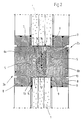
- FIG Section The connection area between two fire protection panes 1 is shown in FIG Section shown.
- a frame construction that can be used is used from two wooden elements 2a, 2b with a strip 3 arranged between them composed of a non-flammable or flame-retardant material.
- the bar 3 is divided into two, and consists of two flat against each other Strips 3a, 3b, which are located between the facing end faces 4 of the fire protection panes 1.
- Figure 2 shows that both strips 3a, 3b together have a smaller thickness than the thickness the fire protection window 1.
- Each of the two strips 3a, 3b of the strip 3 made of non-combustible or flame retardant material is with the adjacent wooden element 2a or 2b bracketed.
- Each of the two wooden elements 2a, 2b consists of the rectangular one Wooden profile 6a, 6b each from two wooden strips 7, 8.
- the wooden strips 7, 8 cover the adjacent edge 9 of the fire protection window 1 and are for this purpose by means of further clamps 11 on the fire protection panes 1 End faces 10 of the wooden profiles 6a, 6b attached.
- Both the wooden profiles 6a, 6b, as well as the wooden strips 7, 8 serving as glass retaining strips can be within certain limits can be freely designed, so the frame construction to influence from an aesthetic point of view. Usually comes as wood Hardwood, but, depending on the application, also softwood. The type of wood used has little influence on the achievable fire and heat resistance of the frame construction. Crucial for this is almost exclusively the effect of the between the Wood profiles 6a, 6b arranged strip 3.
- a narrow strip 12 made of a special fire protection material is arranged. When exposed to heat, the strip 12 foams and closes thus the remaining joint.
- An inside and the edge 9 of the fire protection window 1 is an elastocell tape 13 is arranged.
- a silicone seal 14 prevents dust from entering and moisture.
Landscapes
- Engineering & Computer Science (AREA)
- Civil Engineering (AREA)
- Structural Engineering (AREA)
- Joining Of Glass To Other Materials (AREA)
- Inorganic Insulating Materials (AREA)
- Aiming, Guidance, Guns With A Light Source, Armor, Camouflage, And Targets (AREA)
- Building Environments (AREA)
- Special Wing (AREA)
- Securing Of Glass Panes Or The Like (AREA)
- Glass Compositions (AREA)
Description
- Fig. 1
- in einer Ansicht eine erfindungsgemäße Brandschutzverglasung und
- Fig. 2
- einen Teilschnitt entlang der Linie A-A der Figur 1.
- 1
- Brandschutzscheibe
- 2a
- Holzelement
- 2b
- Holzelement
- 3
- Leiste aus nicht brennbarem bzw. schwer entflammbarem Material
- 3a
- Streifen
- 3b
- Streifen
- 4
- Stirnfläche der Brandschutzscheibe
- 5
- Klammer
- 6
- Kopf
- 6a
- Holzprofil
- 6b
- Holzprofil
- 7
- Holzleiste
- 8
- Holzleiste
- 9
- Rand der Brandschutzscheibe
- 10
- Stirnfläche
- 11
- Klammer
- 12
- Streifen
- 13
- Elastozellband
- 14
- Silikondichtung
- 15
- Abschnitt
Claims (6)
- Brandschutzverglasung zur Vermeidung des Durchtritts von Feuer und Rauch im Brandfall aus einem Raum in einen anderen, mit mindestens zwei einen Schutzwirkstoff enthaltenden Brandschutzscheiben (1), deren Stirnflächen (4) einander zugewandt sind,dadurch gekennzeichnet,mit einer die Brandschutzscheiben (1) einfassenden und haltenden Rahmenkonstruktion,mit mindestens einer einen Teil der Rahmenkonstruktion bildenden Leiste (3) aus einem nicht brennbaren bzw. schwer entflammbaren Material, welche sich zwischen den einander zugewandten Stirnflächen (4) erstreckt,und mit Holzelementen (2a, 2b), die einen anderen Teil der Rahmenkonstruktion bilden und Abschnitte aufweisen, welche sich bis über die Ränder (9) der Flachseiten der Brandschutzscheiben (1) erstrecken und diese abdecken,
daß sich die Leiste (3) innerhalb des durch die einander zugewandten Stirnflächen (4) der Brandschutzscheiben (1) definierten Raumes erstreckt, daß Bestandteil der Holzelemente (2a, 2b) rechteckige Holzprofile (6a, 6b) sind, die flächig an der Leiste (3) anliegen und deren Breite geringer ist als die Breite der Rahmenkonstruktion, und daß Holzleisten (7, 8) an den den Brandschutzscheiben (1) zugewandten Stirnflächen (10) der Holzprofile (6a, 6b) befestigt sind, die die Ränder (9) der Flachseiten der Brandschutzscheiben (1) abdecken und die Brandschutzscheiben (1) halten. - Brandschutzverglasung nach Anspruch 1, dadurch gekennzeichnet, daß die Dicke der Leiste (3) aus nicht brennbarem bzw. schwer entflammbarem Material geringer ist als die Dicke der Brandschutzscheiben (1), und die Holzprofile (6a, 6b) nach innen zu der Leiste (3) hin gerichtete Abschnitte (15) aufweisen, deren Breite im wesentlichen gleich der Breite der Leiste (3), jedoch geringer als die Breite der Rahmenkonstruktion ist.
- Brandschutzverglasung nach Anspruch 1 oder 2, dadurch gekennzeichnet, daß sich die Leiste (3) aus nicht brennbarem bzw. schwer entflammbarem Material aus zwei flach aneinanderliegenden Streifen (3a, 3b) zusammensetzt.
- Brandschutzverglasung nach Anspruch 3, dadurch gekennzeichnet, daß jeder der beiden Streifen (3a, 3b) mit dem jeweils angrenzenden Holzelement (2a bzw. 2b) verschraubt ist, wobei die Köpfe (6) der verwendeten Befestigungsmittel (5) in der Trennebene zwischen den beiden Streifen (3a, 3b) liegen.
- Brandschutzverglasung nach Anspruch 4, gekennzeichnet durch zusätzliche Befestigungsmittel, welche zugleich beiden Streifen (3a, 3b) und mindestens eines der Holzelemente (2a, 2b) durchdringen und miteinander verbinden.
- Brandschutzverglasung nach einem der Ansprüche 1 bis 5, gekennzeichnet durch schmale Streifen (12) aus einem unter Hitzeeinwirkung aufschäumenden Material zwischen der Leiste (3) bzw. den Streifen (3a, 3b) und der Stirnfläche (4) der jeweils angrenzenden Brandschutzscheibe (1).
Applications Claiming Priority (2)
| Application Number | Priority Date | Filing Date | Title |
|---|---|---|---|
| DE29501246U | 1995-01-27 | ||
| DE29501246U DE29501246U1 (de) | 1995-01-27 | 1995-01-27 | Brandschutzverglasung |
Publications (3)
| Publication Number | Publication Date |
|---|---|
| EP0724062A2 EP0724062A2 (de) | 1996-07-31 |
| EP0724062A3 EP0724062A3 (de) | 1997-01-29 |
| EP0724062B1 true EP0724062B1 (de) | 2000-12-13 |
Family
ID=8003020
Family Applications (1)
| Application Number | Title | Priority Date | Filing Date |
|---|---|---|---|
| EP96100239A Expired - Lifetime EP0724062B1 (de) | 1995-01-27 | 1996-01-10 | Brandschutzverglasung |
Country Status (4)
| Country | Link |
|---|---|
| EP (1) | EP0724062B1 (de) |
| AT (1) | ATE198093T1 (de) |
| DE (2) | DE29501246U1 (de) |
| ES (1) | ES2153909T3 (de) |
Cited By (1)
| Publication number | Priority date | Publication date | Assignee | Title |
|---|---|---|---|---|
| DE202010012276U1 (de) | 2010-09-07 | 2010-11-18 | Holzbau Schmid Gmbh & Co. Kg | Türzarge, insbesondere für Brandschutzzwecke |
Families Citing this family (9)
| Publication number | Priority date | Publication date | Assignee | Title |
|---|---|---|---|---|
| DE29501246U1 (de) * | 1995-01-27 | 1995-03-09 | Holzbau Schmid GmbH & Co. KG, 73099 Adelberg | Brandschutzverglasung |
| DE29807809U1 (de) | 1998-04-30 | 1998-07-30 | Siemer & Espeter GmbH, 26683 Saterland | Rahmenelement für eine Brandschutzverglasung |
| DE19929664A1 (de) * | 1999-06-28 | 2001-01-18 | Schoerghuber Spezialtueren | Rahmenholm einer Glasrahmenkonstruktion für Brandschutzverglasungen |
| DE19935199C2 (de) * | 1999-07-27 | 2002-12-12 | Heiko Ritter | Feuerschutztür |
| DE19957025A1 (de) * | 1999-11-09 | 2001-07-12 | Schott Glas | Brandsichere Verglasung mit Lärchenholz |
| DE19957026C2 (de) * | 1999-11-09 | 2003-10-16 | Schott Glas | Brandsichere Verglasung mit Glashalteleistenbefestigung |
| DE202010003492U1 (de) * | 2010-03-11 | 2010-06-02 | Holzbau Schmid Gmbh & Co. Kg | Horizontale Brandschutzverglasung |
| DE202010003982U1 (de) | 2010-03-22 | 2010-08-05 | Holzbau Schmid Gmbh & Co. Kg | Brandschutz-Türzarge aus Holz |
| DE102012111416A1 (de) | 2011-12-01 | 2013-06-06 | IPM Schober Fenster GmbH | Brandschutzfenster |
Family Cites Families (5)
| Publication number | Priority date | Publication date | Assignee | Title |
|---|---|---|---|---|
| DE3413324A1 (de) * | 1984-04-09 | 1985-10-31 | Reiner 5450 Neuwied Biehl | Brandschutzverglasung |
| GB2195386B (en) * | 1986-09-25 | 1991-03-13 | Kenneth Harold Acketts | Fire-retardant screen |
| DE4001677C1 (de) * | 1990-01-22 | 1991-03-14 | Vegla Vereinigte Glaswerke Gmbh, 5100 Aachen, De | |
| DE4421210A1 (de) * | 1993-06-21 | 1994-12-22 | Fachverband Glasdach Und Metal | Feuerwiderstandsfähige Trennwand |
| DE29501246U1 (de) * | 1995-01-27 | 1995-03-09 | Holzbau Schmid GmbH & Co. KG, 73099 Adelberg | Brandschutzverglasung |
-
1995
- 1995-01-27 DE DE29501246U patent/DE29501246U1/de not_active Expired - Lifetime
-
1996
- 1996-01-10 EP EP96100239A patent/EP0724062B1/de not_active Expired - Lifetime
- 1996-01-10 DE DE59606199T patent/DE59606199D1/de not_active Expired - Lifetime
- 1996-01-10 AT AT96100239T patent/ATE198093T1/de active
- 1996-01-10 ES ES96100239T patent/ES2153909T3/es not_active Expired - Lifetime
Cited By (2)
| Publication number | Priority date | Publication date | Assignee | Title |
|---|---|---|---|---|
| DE202010012276U1 (de) | 2010-09-07 | 2010-11-18 | Holzbau Schmid Gmbh & Co. Kg | Türzarge, insbesondere für Brandschutzzwecke |
| EP2426302A1 (de) | 2010-09-07 | 2012-03-07 | Holzbau Schmid GmbH & Co. KG | Türzarge, insbesondere für Brandschutzzwecke |
Also Published As
| Publication number | Publication date |
|---|---|
| DE59606199D1 (de) | 2001-01-18 |
| ES2153909T3 (es) | 2001-03-16 |
| EP0724062A2 (de) | 1996-07-31 |
| EP0724062A3 (de) | 1997-01-29 |
| ATE198093T1 (de) | 2000-12-15 |
| DE29501246U1 (de) | 1995-03-09 |
Similar Documents
| Publication | Publication Date | Title |
|---|---|---|
| DE3432021A1 (de) | Sicherheitsfenster oder -tuer | |
| EP0940512A1 (de) | Plattenförmiges Brandschutzelement in Sandwich-Bauweise | |
| EP0724062B1 (de) | Brandschutzverglasung | |
| EP0658677B1 (de) | Brandschutzverglasung | |
| WO2010097179A1 (de) | Brandschutzverglasung | |
| DE19635409B4 (de) | Glastür für Brandschutzzwecke sowie Verfahren zum Herstellen einer Glastür für Brandschutzzwecke | |
| WO2001004449A1 (de) | Feuerhemmendes flächenelement mit mindestens zwei lichtdurchlässigen brandschutz-glasplatten | |
| EP0498021B1 (de) | Brandschutzverglasung | |
| EP1566514B1 (de) | Mehrteilige Brandschutzverglasung mit integrierter Tür -oder Fensterzarge | |
| EP0505934B1 (de) | Glastür für Brandschutzzwecke | |
| EP3216966A1 (de) | Einrichtung zum schliessen einer öffnung für brandschutzzwecke | |
| DE3502032A1 (de) | Tuer oder tor mit wenigstens einem isolierten fluegel, insbesondere brandschutztor | |
| EP0528354B1 (de) | Beschusshemmendes Isolierglaselement | |
| EP0730068B1 (de) | Dachflächenfenster | |
| DE3604433C1 (en) | Door leaf or window sash and frame configured in a bulletproof manner | |
| DE9400536U1 (de) | Glastür für Brandschutzzwecke | |
| DE69814585T2 (de) | Feuerbeständige Trennwand mit Verglasungselementen | |
| DE4010920A1 (de) | Feuerschutztor | |
| EP0124881B1 (de) | Feuerschutztür mit einem wenigstens im Rahmenbereich aus Holz bestehenden Türblatt | |
| EP0622517B1 (de) | Brandschutztür | |
| EP0670130B1 (de) | Schaukasten zur zugriffssicheren Aufnahme von Objekten, insbesondere Kunstobjekten in Museen und Ausstellungen | |
| DE9103421U1 (de) | Brandschutzverglasung | |
| EP3741947A1 (de) | Trennwand zur bildung eines brandabschnitts in räumen von gebäuden | |
| DE9207156U1 (de) | Brandschutzverglasung in horizontaler Einbaulage | |
| DE20204965U1 (de) | Brandschutzverglasung |
Legal Events
| Date | Code | Title | Description |
|---|---|---|---|
| PUAI | Public reference made under article 153(3) epc to a published international application that has entered the european phase |
Free format text: ORIGINAL CODE: 0009012 |
|
| AK | Designated contracting states |
Kind code of ref document: A2 Designated state(s): AT BE CH DE ES FR GB IT LI NL |
|
| PUAL | Search report despatched |
Free format text: ORIGINAL CODE: 0009013 |
|
| AK | Designated contracting states |
Kind code of ref document: A3 Designated state(s): AT BE CH DE ES FR GB IT LI NL |
|
| 17P | Request for examination filed |
Effective date: 19970311 |
|
| 17Q | First examination report despatched |
Effective date: 19990128 |
|
| GRAG | Despatch of communication of intention to grant |
Free format text: ORIGINAL CODE: EPIDOS AGRA |
|
| GRAG | Despatch of communication of intention to grant |
Free format text: ORIGINAL CODE: EPIDOS AGRA |
|
| GRAH | Despatch of communication of intention to grant a patent |
Free format text: ORIGINAL CODE: EPIDOS IGRA |
|
| GRAH | Despatch of communication of intention to grant a patent |
Free format text: ORIGINAL CODE: EPIDOS IGRA |
|
| GRAA | (expected) grant |
Free format text: ORIGINAL CODE: 0009210 |
|
| AK | Designated contracting states |
Kind code of ref document: B1 Designated state(s): AT BE CH DE ES FR GB IT LI NL |
|
| REF | Corresponds to: |
Ref document number: 198093 Country of ref document: AT Date of ref document: 20001215 Kind code of ref document: T |
|
| REG | Reference to a national code |
Ref country code: CH Ref legal event code: NV Representative=s name: E. BLUM & CO. PATENTANWAELTE Ref country code: CH Ref legal event code: EP |
|
| GBT | Gb: translation of ep patent filed (gb section 77(6)(a)/1977) |
Effective date: 20001213 |
|
| ET | Fr: translation filed | ||
| REF | Corresponds to: |
Ref document number: 59606199 Country of ref document: DE Date of ref document: 20010118 |
|
| ITF | It: translation for a ep patent filed | ||
| REG | Reference to a national code |
Ref country code: ES Ref legal event code: FG2A Ref document number: 2153909 Country of ref document: ES Kind code of ref document: T3 |
|
| PLBE | No opposition filed within time limit |
Free format text: ORIGINAL CODE: 0009261 |
|
| STAA | Information on the status of an ep patent application or granted ep patent |
Free format text: STATUS: NO OPPOSITION FILED WITHIN TIME LIMIT |
|
| 26N | No opposition filed | ||
| REG | Reference to a national code |
Ref country code: GB Ref legal event code: IF02 |
|
| PGFP | Annual fee paid to national office [announced via postgrant information from national office to epo] |
Ref country code: ES Payment date: 20020118 Year of fee payment: 7 |
|
| PG25 | Lapsed in a contracting state [announced via postgrant information from national office to epo] |
Ref country code: ES Free format text: LAPSE BECAUSE OF NON-PAYMENT OF DUE FEES Effective date: 20030111 |
|
| REG | Reference to a national code |
Ref country code: ES Ref legal event code: FD2A Effective date: 20030111 |
|
| REG | Reference to a national code |
Ref country code: CH Ref legal event code: PFA Owner name: HOLZBAU SCHMID GMBH & CO. KG Free format text: HOLZBAU SCHMID GMBH & CO. KG#ZIEGELHAU 1-4#73099 ADELBERG (DE) $ PROMAT GMBH#SCHEIFENKAMP 16#40880 RATINGEN (DE) -TRANSFER TO- HOLZBAU SCHMID GMBH & CO. KG#ZIEGELHAU 1-4#73099 ADELBERG (DE) $ PROMAT GMBH#SCHEIFENKAMP 16#40880 RATINGEN (DE) |
|
| REG | Reference to a national code |
Ref country code: FR Ref legal event code: PLFP Year of fee payment: 20 |
|
| PGFP | Annual fee paid to national office [announced via postgrant information from national office to epo] |
Ref country code: NL Payment date: 20150129 Year of fee payment: 20 |
|
| PGFP | Annual fee paid to national office [announced via postgrant information from national office to epo] |
Ref country code: DE Payment date: 20150121 Year of fee payment: 20 Ref country code: CH Payment date: 20150121 Year of fee payment: 20 Ref country code: IT Payment date: 20150128 Year of fee payment: 20 |
|
| PGFP | Annual fee paid to national office [announced via postgrant information from national office to epo] |
Ref country code: AT Payment date: 20150122 Year of fee payment: 20 Ref country code: GB Payment date: 20150121 Year of fee payment: 20 Ref country code: FR Payment date: 20150122 Year of fee payment: 20 |
|
| PGFP | Annual fee paid to national office [announced via postgrant information from national office to epo] |
Ref country code: BE Payment date: 20150121 Year of fee payment: 20 |
|
| REG | Reference to a national code |
Ref country code: DE Ref legal event code: R071 Ref document number: 59606199 Country of ref document: DE |
|
| REG | Reference to a national code |
Ref country code: NL Ref legal event code: MK Effective date: 20160109 |
|
| REG | Reference to a national code |
Ref country code: CH Ref legal event code: PL |
|
| REG | Reference to a national code |
Ref country code: GB Ref legal event code: PE20 Expiry date: 20160109 |
|
| REG | Reference to a national code |
Ref country code: AT Ref legal event code: MK07 Ref document number: 198093 Country of ref document: AT Kind code of ref document: T Effective date: 20160110 |
|
| PG25 | Lapsed in a contracting state [announced via postgrant information from national office to epo] |
Ref country code: GB Free format text: LAPSE BECAUSE OF EXPIRATION OF PROTECTION Effective date: 20160109 |