EP0724109A1 - Joint à emboîtement pour tuyauterie de fluide à haute pression - Google Patents
Joint à emboîtement pour tuyauterie de fluide à haute pression Download PDFInfo
- Publication number
- EP0724109A1 EP0724109A1 EP95119416A EP95119416A EP0724109A1 EP 0724109 A1 EP0724109 A1 EP 0724109A1 EP 95119416 A EP95119416 A EP 95119416A EP 95119416 A EP95119416 A EP 95119416A EP 0724109 A1 EP0724109 A1 EP 0724109A1
- Authority
- EP
- European Patent Office
- Prior art keywords
- ring
- ring section
- plug
- conical
- section
- Prior art date
- Legal status (The legal status is an assumption and is not a legal conclusion. Google has not performed a legal analysis and makes no representation as to the accuracy of the status listed.)
- Granted
Links
- 239000012530 fluid Substances 0.000 title 1
- 239000002184 metal Substances 0.000 claims abstract description 6
- 238000003780 insertion Methods 0.000 claims description 15
- 230000037431 insertion Effects 0.000 claims description 15
- 238000000034 method Methods 0.000 claims description 5
- 230000006978 adaptation Effects 0.000 claims description 2
- 239000011324 bead Substances 0.000 claims description 2
- 238000003825 pressing Methods 0.000 claims description 2
- 238000007789 sealing Methods 0.000 description 5
- 230000008878 coupling Effects 0.000 description 1
- 238000010168 coupling process Methods 0.000 description 1
- 238000005859 coupling reaction Methods 0.000 description 1
- 238000005520 cutting process Methods 0.000 description 1
- 230000000694 effects Effects 0.000 description 1
- 238000009472 formulation Methods 0.000 description 1
- 238000004519 manufacturing process Methods 0.000 description 1
- 239000000463 material Substances 0.000 description 1
- 239000007769 metal material Substances 0.000 description 1
- 239000000203 mixture Substances 0.000 description 1
- 238000007493 shaping process Methods 0.000 description 1
Images

Classifications
-
- F—MECHANICAL ENGINEERING; LIGHTING; HEATING; WEAPONS; BLASTING
- F16—ENGINEERING ELEMENTS AND UNITS; GENERAL MEASURES FOR PRODUCING AND MAINTAINING EFFECTIVE FUNCTIONING OF MACHINES OR INSTALLATIONS; THERMAL INSULATION IN GENERAL
- F16L—PIPES; JOINTS OR FITTINGS FOR PIPES; SUPPORTS FOR PIPES, CABLES OR PROTECTIVE TUBING; MEANS FOR THERMAL INSULATION IN GENERAL
- F16L37/00—Couplings of the quick-acting type
- F16L37/08—Couplings of the quick-acting type in which the connection between abutting or axially overlapping ends is maintained by locking members
- F16L37/084—Couplings of the quick-acting type in which the connection between abutting or axially overlapping ends is maintained by locking members combined with automatic locking
- F16L37/088—Couplings of the quick-acting type in which the connection between abutting or axially overlapping ends is maintained by locking members combined with automatic locking by means of a split elastic ring
Definitions
- the present invention relates to a plug-in connection for pressure medium lines, with a housing part having a receiving opening for inserting a plug part and with a radially elastically deformable, mounted within the receiving opening, for locking the inserted plug part into an retaining ring which engages on the outer ring groove.
- EP-B-0 300 023 describes such a plug connection, but it is disadvantageous that the retaining ring designed there as a wire snap ring can slide eccentrically within the annular chamber, particularly when the plug axis is in a "lying", ie not vertical, position before the plug part is inserted, which then hinders the insertion of the plug part.
- there is therefore an outer cone on the plug part which is used for (re) centering and for expanding the snap ring. Because of the risk of the eccentric slipping of the snap ring, this outer cone must be very long and pronounced, which means that disadvantageously, the entire connector also has a relatively large length.
- a similar quick connect coupling is known from DE-OS 27 48 157.
- a locking or securing ring in the event of an eccentric slipping during the plugging process only has to be centered again by a slope or a cone of the plug.
- the present invention has for its object to provide a connector of the generic type, which is characterized by a particularly compact design, in particular length, but can still be inserted lying in any spatial orientation without any problems, with a structurally simple and inexpensive design in particular the retaining ring low insertion forces, but sufficiently high holding forces are to be achieved.
- the retaining ring is formed as a sheet metal part with a flanged locking ring section for engaging in the outer ring groove of the plug part and with a ring section adjoining the locking ring section in the direction of insertion, the locking ring section being radially elastically deformable in that it is formed by at least three slots distributed over the ring circumference and extending in the axial direction into the conical ring section are divided into at least three ring sectors.
- the main advantage here is Conically enlarged ring section, by means of which the retaining ring is supported in the receiving opening of the housing part in a self-centering manner according to the invention. In this way, an eccentric slipping of the retaining ring is effectively avoided, so that a pronounced outer cone on the plug part can advantageously be practically unnecessary. Only a slight chamfer needs to be present on the plug part in order to bring about the radial expansion of the retaining ring in the region of the flanged locking ring section. Thus, the length is considerably reduced by the needless "centering and positioning cone". Nevertheless, the retaining ring is always held centrally even when the plug connection is arranged horizontally, so that the plugging process is always possible without any problems.
- the plug-in force required to insert the plug is advantageously very low. Nevertheless, a very high holding force against pulling out of the plug part is achieved by the holding ring engaging with the locking ring section in a form-fitting or at least force-fitting manner in the outer ring groove of the plug part and, due to a specific inner contour of the receiving opening, also being held firmly and securely in the outer ring groove when tensile forces occur. In this case, it is advantageously also possible to influence or adjust the insertion and holding forces by suitable shaping of the slots dividing the ring sectors.
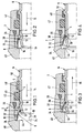
- a plug connection mainly consists of a housing part 2 with a receiving opening 4 for inserting a plug part 6.
- a receiving opening 4 which is designed as a so-called "shaped bore”
- a radially elastically deformable retaining ring 8 mounted, which is elastically expandable in the radial direction when the plug part 6 is inserted and then, at least in regions, snaps into an preferably annular groove 10 on the plug part 6 to lock it. This locked state is illustrated in Fig. 4.
- This retaining ring 8 is, according to the invention, a molded sheet metal part, and preferably specifically a deep-drawn part, made of spring sheet metal with a flanged locking ring section 12 for engaging in the outer ring groove 10 of the plug part 6 and with an in the insertion direction (arrow 14 in FIGS. 1 and 2) on the locking section 12 adjoining and conically widening ring section 16 is formed.
- the locking ring section 12 is radially elastically deformable (expandable) in that it has at least three slots 18 in at least three ring sectors, which are particularly evenly distributed over the ring circumference and extend in the axial direction into the conical ring section 16 by at least three - in the preferred exemplary embodiment shown four 20 is divided. As illustrated, four ring sectors 20 are preferably present, each extending approximately over an angle of 90 °, minus the angular extent or width of one of the slots 18 in each case.
- a slot 22 which is continuous in the axial direction is preferably provided at one point on the circumference of the retaining ring 8 for separating two adjacent ring sectors 20.
- This preferred embodiment facilitates the assembly of the retaining ring 8 in that it can be reduced in diameter for insertion into the receiving opening 8 until it widens again in its insertion position in a spring-elastic manner.
- the slots 18 subdividing the locking ring section 12 - apart from the preferably existing, axially continuous slot 22 - as far as in the axial direction extend approximately central region of the conical ring portion 16.
- the conical ring section 16 preferably has second slots 24 axially opposite the first-mentioned slots 18 in such a way that the ring sectors 20 are connected to one another via connecting webs 26 arranged approximately centrally in the axial direction and extending in the circumferential direction. Such a connecting web 26 is then missing in the area of the continuous slot 22.
- a kind of "torsion spring” is formed through the slots 18, 24 and possibly 22, which, when the plug part 6 is inserted, about a torsion axis running in the circumferential direction and approximately centrally arranged in the axial direction 28 killed.
- This torsional movement is illustrated in FIG. 6 by the double arrows 30 shown.
- the sheet metal material starting from the region of the smaller diameter of the conical ring section 16, is beaded or rolled radially inwards like a bead.
- the retaining ring 8 is advantageously supported in the receiving opening 4 of the housing part 2 via the conical ring part 16.
- the receiving opening 4 of the housing part 2 in adaptation to the retaining ring 8 and its deformability according to the invention has such an inner contour that when inserting the plug part 6 the torsion or twisting of the retaining ring already described above 8 or the ring sectors 20 relative to one another about the torsion axis 28 running in the circumferential direction is possible or is even supported, as a result of which the locking ring section 12 expands and subsequently snaps into the outer ring groove 10 of the plug part 6.
- This function is easy to understand on the basis of the insertion states illustrated in FIGS. 1 to 4.
- the receiving opening 4 preferably has an inner contour with a ring contact area 32 - forming a kind of "rocker bearing" - for the approximately axially central area of the connecting webs 26 of the retaining ring 8, with an extension 34 for the end area of the conical ring section 16, with a constriction 36 for pressing in of the locking ring section 12 into the connector part outer ring groove 10 when the connector part 6 is pulled (see FIG.
- the ring contact area 32 is designed as an annular surface which widens conically in the direction of insertion (arrows 14).
- the constriction 36 is preferably designed as a conical surface tapering counter to the insertion direction, preferably up to an inner diameter of the receiving opening 4 which substantially corresponds to the outer diameter of the plug part 6.
- the conical ring surface forming the ring contact area 32 and the die are preferred
- the conical surface forming the constriction 36 forms part of a common conical surface interrupted by the enlarged annular chamber 38, on which the retaining ring 8 preferably bears over a large area in the locked state (FIG. 4), namely with the locking ring section 12 and the conical ring section 16.
- the retaining ring 8 When the plug part 6 is inserted in the direction of the arrow 14, the retaining ring 8 is axially displaced in the same direction until the locking ring section 12 reaches the area of the annular chamber 38 and can expand there in the radial direction (FIGS. 1 and 2). After snapping into the connector outer ring groove 10 and at - e.g. due to pressure - pulling the plug part 6 in the direction of arrow 15 (FIG. 3), the retaining ring is taken along, so that the locking ring section 12 reaches the area of the constriction 36 and is held by the latter in the outer ring groove 10 in a form-fitting manner (locking state in FIG. 4).
- the housing part 2 is designed in two parts for the purpose of releasability of the connection; it consists of a base part 40 and an insert part 42 detachably connected thereto.
- the insert part 42 is preferably designed as a screw-in part and engages with an external thread in an internal thread of the base part 40.
- the extension 34 for the end region of the conical ring section 16 is formed in the form of an inner annular groove in the axial direction between an end ring surface of the insert part 42 and a ring step 44 of the base part 40. This makes it possible to separate the insert part 42 from the base part 40 and to remove it together with the plug part 6.
- the conical ring section 16 of the retaining ring 8 is then advantageous accessible from the outside, so that the ring sectors 20 are deformed manually or by means of a suitable tool for the purpose of widening the locking ring section 12 and the retaining ring 8 can thus be detached from the plug part 6.
- the plug part 6 can then be removed from the receiving opening 4 of the housing part 2 or the insert part 42.
- a sealing ring 46 is arranged on the one hand in an inner ring groove of the housing part 2, which sealing ring is placed on the outer circumference of the plug part 6.
- a further sealing ring 48 is preferably additionally provided, which is arranged approximately in the mouth region of the receiving opening 4 and which cooperates in a sealing manner with an outer ring web 50 of the plug part. It is preferably provided here that the ring web 50 - as well as the outer ring groove 10 and an outer cone 52 on the plug-in side - are formed without cutting by upsetting a tube material of the plug part 6.
- the invention is not limited to the exemplary embodiments shown and described, but also encompasses all embodiments having the same effect in the sense of the invention. Furthermore, the invention has not yet been limited to the combination of features defined in claim 1, but can also be defined by any other combination of specific features of all the individual features disclosed in total. This means that in principle practically every single feature of claim 1 can be omitted or replaced by at least one single feature disclosed elsewhere in the application. In this respect, claim 1 is only to be understood as a first attempt at formulation for an invention.
Landscapes
- Engineering & Computer Science (AREA)
- General Engineering & Computer Science (AREA)
- Mechanical Engineering (AREA)
- Quick-Acting Or Multi-Walled Pipe Joints (AREA)
- Snaps, Bayonet Connections, Set Pins, And Snap Rings (AREA)
- Cable Accessories (AREA)
- Coupling Device And Connection With Printed Circuit (AREA)
Applications Claiming Priority (2)
| Application Number | Priority Date | Filing Date | Title |
|---|---|---|---|
| DE29501006U DE29501006U1 (de) | 1995-01-24 | 1995-01-24 | Steckverbindung für Druckmittelleitungen |
| DE29501006U | 1995-01-24 |
Publications (2)
| Publication Number | Publication Date |
|---|---|
| EP0724109A1 true EP0724109A1 (fr) | 1996-07-31 |
| EP0724109B1 EP0724109B1 (fr) | 2000-03-08 |
Family
ID=8002838
Family Applications (1)
| Application Number | Title | Priority Date | Filing Date |
|---|---|---|---|
| EP95119416A Expired - Lifetime EP0724109B1 (fr) | 1995-01-24 | 1995-12-09 | Joint à emboítement pour tuyauterie de fluide à haute pression |
Country Status (2)
| Country | Link |
|---|---|
| EP (1) | EP0724109B1 (fr) |
| DE (2) | DE29501006U1 (fr) |
Cited By (1)
| Publication number | Priority date | Publication date | Assignee | Title |
|---|---|---|---|---|
| EP0813017A3 (fr) * | 1996-06-14 | 1998-11-11 | Armaturenfabrik Hermann Voss GmbH + Co. | Raccord emboitable pour systèmes sous pression |
Families Citing this family (2)
| Publication number | Priority date | Publication date | Assignee | Title |
|---|---|---|---|---|
| DE19529080A1 (de) * | 1995-08-08 | 1997-02-13 | Voss Armaturen | Steckverbindung für Druckmittelleitungen |
| US12025255B2 (en) | 2021-04-23 | 2024-07-02 | Eaton Intelligent Power Limited | Quick action fluid coupler |
Citations (7)
| Publication number | Priority date | Publication date | Assignee | Title |
|---|---|---|---|---|
| DE2748157A1 (de) | 1976-10-27 | 1978-05-11 | Weatherhead Co | Schnellverbindungskupplung |
| DE2953463A1 (de) * | 1978-06-07 | 1980-12-11 | Voss Armaturen | Verbindungssystem fuer druckleitungen |
| GB2153028A (en) * | 1984-01-20 | 1985-08-14 | Rasmussen Gmbh | Plug-type coupling |
| EP0240452A1 (fr) * | 1986-03-31 | 1987-10-07 | Noam Lemelshtrich | Raccord rapide, en particulier pour accoupler des tuyaux |
| US4842309A (en) * | 1987-05-20 | 1989-06-27 | Schmelzer Corporation | Quick-connect fluid fitting assembly |
| WO1992008074A1 (fr) * | 1990-10-24 | 1992-05-14 | Ford Motor Company Limited | Raccord de tuyau |
| DE9420380U1 (de) * | 1994-12-20 | 1995-02-02 | Armaturenfabrik Hermann Voss GmbH + Co, 51688 Wipperfürth | Steckverbindung |
-
1995
- 1995-01-24 DE DE29501006U patent/DE29501006U1/de not_active Expired - Lifetime
- 1995-12-09 DE DE59507954T patent/DE59507954D1/de not_active Expired - Lifetime
- 1995-12-09 EP EP95119416A patent/EP0724109B1/fr not_active Expired - Lifetime
Patent Citations (7)
| Publication number | Priority date | Publication date | Assignee | Title |
|---|---|---|---|---|
| DE2748157A1 (de) | 1976-10-27 | 1978-05-11 | Weatherhead Co | Schnellverbindungskupplung |
| DE2953463A1 (de) * | 1978-06-07 | 1980-12-11 | Voss Armaturen | Verbindungssystem fuer druckleitungen |
| GB2153028A (en) * | 1984-01-20 | 1985-08-14 | Rasmussen Gmbh | Plug-type coupling |
| EP0240452A1 (fr) * | 1986-03-31 | 1987-10-07 | Noam Lemelshtrich | Raccord rapide, en particulier pour accoupler des tuyaux |
| US4842309A (en) * | 1987-05-20 | 1989-06-27 | Schmelzer Corporation | Quick-connect fluid fitting assembly |
| WO1992008074A1 (fr) * | 1990-10-24 | 1992-05-14 | Ford Motor Company Limited | Raccord de tuyau |
| DE9420380U1 (de) * | 1994-12-20 | 1995-02-02 | Armaturenfabrik Hermann Voss GmbH + Co, 51688 Wipperfürth | Steckverbindung |
Cited By (1)
| Publication number | Priority date | Publication date | Assignee | Title |
|---|---|---|---|---|
| EP0813017A3 (fr) * | 1996-06-14 | 1998-11-11 | Armaturenfabrik Hermann Voss GmbH + Co. | Raccord emboitable pour systèmes sous pression |
Also Published As
| Publication number | Publication date |
|---|---|
| DE29501006U1 (de) | 1995-03-02 |
| EP0724109B1 (fr) | 2000-03-08 |
| DE59507954D1 (de) | 2000-04-13 |
Similar Documents
| Publication | Publication Date | Title |
|---|---|---|
| EP0665402B1 (fr) | Connecteur à fiche pour systèmes de conduites sous pression | |
| DE102007047860B3 (de) | Verbindungselement mit einer Schraube und einer daran unverlierbar angeordneten Hülse | |
| EP1199506B1 (fr) | Dispositif de raccordement pour tuyaux de pression | |
| EP2136088B1 (fr) | Elément de liaison doté d'une vis et d'une douille agencée sur celle-ci de façon inamovible | |
| EP1152497A2 (fr) | Connecteur circulaire | |
| EP0005865A2 (fr) | Système de liaison enfichable pour conduites sous pression, en particulier pour conduites de système de freinage | |
| DE29900796U1 (de) | Vorrichtung zum Verbinden eines Rohrstutzens, rohrförmigen Armaturenteils oder Fittings mit einem Rohr | |
| EP1288554A1 (fr) | Dispositif de connexion pour un tube | |
| EP0860643A2 (fr) | Raccord enfichable sous pression | |
| EP0397150A2 (fr) | Unité de broche et douille de contact | |
| DE60303724T2 (de) | Federeinheit und Herstellungsmethode dafür | |
| EP0132673A2 (fr) | Dispositif de raccordement pour conduits sous pression | |
| EP3645926A1 (fr) | Manchon de sertissage | |
| DE19803918A1 (de) | Anschlußvorrichtung für Rohrleitungen | |
| EP0774611A1 (fr) | Procédé de fabrication d'un raccord de tuyaux et dispositif de raccordement pour la fabrication d'un raccord de tuyaux | |
| EP2281136B1 (fr) | Raccord à emboîtement pour conduites de fluide | |
| EP0718538A1 (fr) | Raccord enfichables | |
| EP0881421A2 (fr) | Raccord emboítable pour systèmes à fluide sous pression | |
| EP0740100A1 (fr) | Joint à emboîtement pour tuyauterie de fluide à haute pression | |
| DE102007062830B4 (de) | Verfahren und Vorrichtung zum Herstellen eines Gewindes sowie Bauteil und Gerät | |
| DE10200574C1 (de) | Steckverbindung für den Anschluß von Rohrleitungen | |
| EP0285703B1 (fr) | Connecteur à boîtier et a pièce d'insertion de contact | |
| EP0724109A1 (fr) | Joint à emboîtement pour tuyauterie de fluide à haute pression | |
| DE19819758A1 (de) | Steckverbindung für Rohrleitungen | |
| AT526773B1 (de) | Steckhülse und Verbindungshülse mit Steckhülse |
Legal Events
| Date | Code | Title | Description |
|---|---|---|---|
| PUAI | Public reference made under article 153(3) epc to a published international application that has entered the european phase |
Free format text: ORIGINAL CODE: 0009012 |
|
| AK | Designated contracting states |
Kind code of ref document: A1 Designated state(s): DE FR IT SE |
|
| 17P | Request for examination filed |
Effective date: 19960904 |
|
| 17Q | First examination report despatched |
Effective date: 19980318 |
|
| GRAG | Despatch of communication of intention to grant |
Free format text: ORIGINAL CODE: EPIDOS AGRA |
|
| GRAG | Despatch of communication of intention to grant |
Free format text: ORIGINAL CODE: EPIDOS AGRA |
|
| GRAH | Despatch of communication of intention to grant a patent |
Free format text: ORIGINAL CODE: EPIDOS IGRA |
|
| GRAH | Despatch of communication of intention to grant a patent |
Free format text: ORIGINAL CODE: EPIDOS IGRA |
|
| GRAA | (expected) grant |
Free format text: ORIGINAL CODE: 0009210 |
|
| AK | Designated contracting states |
Kind code of ref document: B1 Designated state(s): DE FR IT SE |
|
| ITF | It: translation for a ep patent filed | ||
| REF | Corresponds to: |
Ref document number: 59507954 Country of ref document: DE Date of ref document: 20000413 |
|
| ET | Fr: translation filed | ||
| PLBE | No opposition filed within time limit |
Free format text: ORIGINAL CODE: 0009261 |
|
| STAA | Information on the status of an ep patent application or granted ep patent |
Free format text: STATUS: NO OPPOSITION FILED WITHIN TIME LIMIT |
|
| 26N | No opposition filed | ||
| REG | Reference to a national code |
Ref country code: FR Ref legal event code: CD |
|
| PGFP | Annual fee paid to national office [announced via postgrant information from national office to epo] |
Ref country code: SE Payment date: 20081205 Year of fee payment: 14 Ref country code: IT Payment date: 20081127 Year of fee payment: 14 |
|
| EUG | Se: european patent has lapsed | ||
| PG25 | Lapsed in a contracting state [announced via postgrant information from national office to epo] |
Ref country code: IT Free format text: LAPSE BECAUSE OF NON-PAYMENT OF DUE FEES Effective date: 20091209 |
|
| PG25 | Lapsed in a contracting state [announced via postgrant information from national office to epo] |
Ref country code: SE Free format text: LAPSE BECAUSE OF NON-PAYMENT OF DUE FEES Effective date: 20091210 |
|
| PGFP | Annual fee paid to national office [announced via postgrant information from national office to epo] |
Ref country code: FR Payment date: 20111219 Year of fee payment: 17 |
|
| PGFP | Annual fee paid to national office [announced via postgrant information from national office to epo] |
Ref country code: DE Payment date: 20120229 Year of fee payment: 17 |
|
| REG | Reference to a national code |
Ref country code: FR Ref legal event code: ST Effective date: 20130830 |
|
| PG25 | Lapsed in a contracting state [announced via postgrant information from national office to epo] |
Ref country code: DE Free format text: LAPSE BECAUSE OF NON-PAYMENT OF DUE FEES Effective date: 20130702 |
|
| REG | Reference to a national code |
Ref country code: DE Ref legal event code: R119 Ref document number: 59507954 Country of ref document: DE Effective date: 20130702 |
|
| PG25 | Lapsed in a contracting state [announced via postgrant information from national office to epo] |
Ref country code: FR Free format text: LAPSE BECAUSE OF NON-PAYMENT OF DUE FEES Effective date: 20130102 |