EP0724109B1 - Steckverbindung für Druckmittelleitungen - Google Patents
Steckverbindung für Druckmittelleitungen Download PDFInfo
- Publication number
- EP0724109B1 EP0724109B1 EP95119416A EP95119416A EP0724109B1 EP 0724109 B1 EP0724109 B1 EP 0724109B1 EP 95119416 A EP95119416 A EP 95119416A EP 95119416 A EP95119416 A EP 95119416A EP 0724109 B1 EP0724109 B1 EP 0724109B1
- Authority
- EP
- European Patent Office
- Prior art keywords
- plug
- ring
- ring section
- locking
- connection according
- Prior art date
- Legal status (The legal status is an assumption and is not a legal conclusion. Google has not performed a legal analysis and makes no representation as to the accuracy of the status listed.)
- Expired - Lifetime
Links
- 239000012530 fluid Substances 0.000 title description 2
- 239000002184 metal Substances 0.000 claims description 4
- 239000011324 bead Substances 0.000 claims description 2
- 238000003780 insertion Methods 0.000 description 13
- 230000037431 insertion Effects 0.000 description 13
- 238000007789 sealing Methods 0.000 description 4
- 238000000034 method Methods 0.000 description 3
- 230000000694 effects Effects 0.000 description 2
- 230000013011 mating Effects 0.000 description 2
- 229910000639 Spring steel Inorganic materials 0.000 description 1
- 230000006978 adaptation Effects 0.000 description 1
- 238000006073 displacement reaction Methods 0.000 description 1
- 239000000463 material Substances 0.000 description 1
- 239000007769 metal material Substances 0.000 description 1
Images

Classifications
-
- F—MECHANICAL ENGINEERING; LIGHTING; HEATING; WEAPONS; BLASTING
- F16—ENGINEERING ELEMENTS AND UNITS; GENERAL MEASURES FOR PRODUCING AND MAINTAINING EFFECTIVE FUNCTIONING OF MACHINES OR INSTALLATIONS; THERMAL INSULATION IN GENERAL
- F16L—PIPES; JOINTS OR FITTINGS FOR PIPES; SUPPORTS FOR PIPES, CABLES OR PROTECTIVE TUBING; MEANS FOR THERMAL INSULATION IN GENERAL
- F16L37/00—Couplings of the quick-acting type
- F16L37/08—Couplings of the quick-acting type in which the connection between abutting or axially overlapping ends is maintained by locking members
- F16L37/084—Couplings of the quick-acting type in which the connection between abutting or axially overlapping ends is maintained by locking members combined with automatic locking
- F16L37/088—Couplings of the quick-acting type in which the connection between abutting or axially overlapping ends is maintained by locking members combined with automatic locking by means of a split elastic ring
Definitions
- the present invention relates to a connector for Pressure fluid lines, with a receiving opening for Inserting a connector part and housing part with a radially elastic stored within the receiving opening deformable, for locking the inserted Plug part engaging in an existing outer ring groove on this Retaining ring.
- EP-B-0 300 describes 023 such a connector, but it is disadvantageous that the retaining ring designed there as a snap ring especially with "lying", i.e. not vertical arrangement the thru axle before inserting the plug part inside the ring chamber can eccentrically slip what but then the insertion of the plug part is hindered. Around To avoid the latter is therefore an outer cone on the connector part available, the for (re) centering and expanding of the snap ring. Because of the risk of eccentric The wire snap ring must slip Outer cone but very long and distinctive, which means disadvantageously, the entire connector also has a relatively large overall length.
- a similar quick connector is from DE-OS 27 48 157 known.
- a closure or Circlip in case of eccentric slipping when plugging in again by a slope or a The cone of the connector.
- US-A-4 842 309 also describes such a connection.
- the present invention has for its object a To create a connector of the generic type that particularly compact design, in particular overall length, distinguished, but still in any Space orientation can be easily inserted horizontally, whereby also with structurally simple and inexpensive design in particular the retaining ring has low insertion forces, however, sufficiently high holding forces can be achieved should.
- the retaining ring as a sheet metal part with a flanged locking ring section for engaging in the outer ring groove of the Plug part and with one in the direction of insertion the locking ring section adjoining and flared Ring section is formed, the locking ring section is thereby radially elastic deformable, that it is distributed by at least three over the circumference of the ring arranged, in the axial direction in the conical Ring section extending slots in at least three Ring sectors is divided.
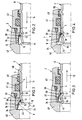
- FIGS. 1 to 4 there is a connector according to the invention mainly from a housing part 2 with a receiving opening 4 for insertion a connector part 6.
- a receiving opening 4 for insertion a connector part 6.
- a radially elastically deformable retaining ring 8 stored when inserting the plug part 6 in the radial direction is elastically expandable and then for locking the plug part 6 at least in some areas into an existing preferably groove-like outer ring groove 10 engages.
- This locked state is illustrated in Fig. 4.
- this retaining ring 8 is in the form of a sheet metal part, preferably as a deep-drawn part made of spring steel with a flanged locking ring section 12 for Intervene in the outer ring groove 10 of the connector part 6 and with one in the insertion direction (arrow 14 in Fig. 1 and 2) adjoining the locking section 12 and itself conically widening ring section 16 is formed.
- the locking ring section 12 is thereby radially elastic deformable (expandable) that it by at least three - in illustrated preferred embodiment four - over the ring circumference, in particular, evenly distributed, itself in the axial direction up to the conical ring section 16 extending slots 18 in at least three Ring sectors 20 is divided.
- ring sectors 20 are preferred - as shown - Four ring sectors 20 available, each one extend approximately over an angle of 90 °, minus the Angular extent or width of one of the slots 18th
- the Locking ring section 12 dividing slots 18 - apart of the preferably existing, axially continuous Slot 22 - seen in the axial direction extend approximately central region of the conical ring portion 16.
- the conical ring section 16 then has preferably the axially mentioned first slots 18 opposite second slots 24 on that the ring sectors 20 seen in the axial direction approximately in the middle arranged, extending in the circumferential direction connecting webs 26 are connected.
- In the area of continuous Slot 22 is then missing such a connecting web 26.
- Through the slots 18, 24 and possibly 22 is one Kind "torsion spring" formed when inserting the Plug part 6 around a circumferential and Torsion axis arranged approximately centrally in the axial direction 28 killed.
- the sheet metal material is used to form the locking ring section 12 starting from the area of the smaller diameter of the conical ring section 16 radially inwards beaded or rolled like a bead.
- the retaining ring 8 is advantageously self-centering in the receiving opening 4 of the housing part 2 supported.
- the receiving opening 4 preferably has an inner contour with a - a kind of "rocker bearing” forming - ring contact area 32 for the approximately axially central Area of the connecting webs 26 of the retaining ring 8, with an extension 34 for the end region of the conical ring section 16, with a constriction 36 for pressing in Locking ring section 12 in the male part outer ring groove 10 when pulling on the plug part 6 (see Fig.
- the ring contact area 32 as one in the direction of insertion (arrows 14) conically widening ring surface is formed.
- the constriction 36 as opposed to the Insertion direction preferably up to approximately one corresponding to the outer diameter of the plug part 6 Inner diameter of the receiving opening 4 tapering Conical surface formed.
- the ring contact area is preferred 32 conical ring surface and the Narrowing 36 conical surface forming part of a common, interrupted by the enlarged annular chamber 38 Conical surface on which the retaining ring 8 is preferably in the locked state (Fig. 4) lies over a large area, with the Locking ring section 12 and the conical ring section 16.
- the housing part 2 for the purpose of releasability of the connection formed in two parts; it consists of a base part 40 and an insert part 42 detachably connected thereto.
- the insert part 42 is preferably designed as a screw-in part and engages with an external thread in an internal thread of the base part 40.
- the extension 34 for the end region of the conical ring section 16 in shape an inner annular groove is formed. This makes it possible to separate the insert part 42 from the base part 40 and together with the plug part 6.
- the conical ring section 16 of the retaining ring 8 accessible from the outside, so that the ring sectors 20 manually or using a suitable tool for expansion of the locking ring portion 12 deformed and so the retaining ring 8 can be detached from the connector part 6. Then it can the plug part 6 from the receiving opening 4 of the housing part 2 or the insert part 42 are removed.
- a sealing ring 46 is arranged, of the sealing surface on the outer circumference of the plug part 6 arrives.
- an additional sealing ring 48 is provided, approximately in the mouth area the receiving opening 4 is arranged, and with an outer ring web 50 of the plug part cooperates sealingly. It is preferably provided that the Ring web 50 - as well as the outer ring groove 10 and an insertion side Outer cone 52 - without cutting by upsetting one Pipe material of the connector part 6 are formed.
Landscapes
- Engineering & Computer Science (AREA)
- General Engineering & Computer Science (AREA)
- Mechanical Engineering (AREA)
- Snaps, Bayonet Connections, Set Pins, And Snap Rings (AREA)
- Quick-Acting Or Multi-Walled Pipe Joints (AREA)
- Coupling Device And Connection With Printed Circuit (AREA)
- Cable Accessories (AREA)
Description
- Fig. 1 bis 3
- jeweils im Halbaxialschnitt eine erfindungsgemäße Steckverbindung in verschiedenen Phasen des Einsteckvorganges,
- Fig. 4
- eine Darstellung analog zu Fig. 1 bis 3, jedoch in der Arretierstellung des Steckerteils,
- Fig. 5
- eine Draufsicht in axialer Richtung auf einen erfindungsgemäßen Haltering (Pfeilrichtung V gemäß Fig. 6) und
- Fig. 6
- einen Schnitt entlang der Schnittlinie VI-VI in Fig. 5.
Claims (13)
- Steckverbindung für Druckmittelleitungen, mit einem eine Aufnahmeöffnung (4) zum Einstecken eines Steckerteils (6) aufweisenden Gehäuseteil (2) und mit einem innerhalb der Aufnahmeöffnung (4) gelagerten, radialelastisch verformbaren, zum Arretieren des eingesteckten Steckerteils (6) in eine an diesem vorhandene Außenringnut (10) eingreifenden Haltering (8),
dadurch gekennzeichnet, daß der Haltering (8) als Blechformteil mit einem umgebördelten Arretierringabschnitt (12) zum Eingreifen in die Außenringnut (10) des Steckerteils (6) sowie mit einem sich in Einsteckrichtung (14) an den Arretierringabschnitt (12) anschließenden und konisch erweiternden Ringabschnitt (16) ausgebildet ist, wobei der Arretierringabschnitt (12) dadurch radialelastisch verformbar ist, daß er durch mindestens drei über den Ringumfang verteilt angeordnete, sich in axialer Richtung in den konischen Ringabschnitt (16) erstrekkende Schlitze (18) in mindestens drei Ringsektoren (20) unterteilt ist. - Steckverbindung nach Anspruch 1
dadurch gekennzeichnet, daß sich die den Arretierringabschnitt (12) unterteilenden Schlitze (18) - abgesehen von einem vorzugsweise vorgesehenen, in axialer Richtung durchgehenden Schlitz (22) - bis in den in axialer Richtung etwa mittigen Bereich des konischen Ringabschnitts (16) erstrecken, wobei vorzugsweise der konische Ringabschnitt (16) derart den Schlitzen (18) axial gegenüberliegende zweite Schlitze (24) aufweist, daß die Ringsektoren (20) über in axialer Richtung gesehen etwa mittig angeordnete, in Umfangsrichtung verlaufende Verbindungsstege (26) miteinander verbunden sind. - Steckverbindung nach Anspruch 1 oder 2,
dadurch gekennzeichnet, daß der Arretieringabschnitt (12) ausgehend von dem konischen Ringabschnitt (16) radial nach innen wulstartig umgebördelt bzw. -gerollt ist. - Steckverbindung nach einem oder mehreren der Ansprüche 1 bis 3,
dadurch gekennzeichnet, daß der Haltering (8) über den konischen Ringteil (16) selbstzentrierend in der Aufnahmeöffnung (4) des Gehäuseteils (2) abgestützt ist. - Steckverbindung nach einem oder mehreren der Ansprüche 1 bis 4,
dadurch gekennzeichnet, daß die Aufnahmeöffnung (4) des Gehäuseteils (2) in Anpassung an den Haltering (8) und dessen Verformbarkeit eine derartige Innenkontur aufweist, daß beim Einstecken des Steckerteils (6) eine Torsion des Halteringes (8) bzw. der Ringsektoren (20) um eine in Umfangsrichtung verlaufende Torsionsachse (28) derart erfolgt, daß sich der Arretieringabschnitt (12) aufweitet und nachfolgend in die Außenringnut (10) des Steckerteils (6) einrastet. - Steckverbindung nach Anspruch 5,
dadurch gekennzeichnet, daß die Aufnahmeöffnung (4) eine Innenkontur mit einem Ringanlagebereich (32) für den etwa axialmittigen Bereich des Halteringes (8), mit einer Erweiterung (34) für den Endbereich des konischen Ringabschnittes (16), mit einer Verengung (36) zum Eindrücken des Arretierringabschnittes (12) in die Steckerteil-Außenringnut (10) sowie mit einer zwischen dem Ringanlagebereich (32) und der Verengung (36) angeordneten Ringkammer (38) zur Aufnahme des sich beim Steckvorgang elastisch aufweitenden Arretierringabschnittes (12) aufweist. - Steckverbindung nach Anspruch 6,
dadurch gekennzeichnet, daß der Ringanlagebereich (32) als eine sich in Einsteckrichtung konisch erweiternde Ringfläche ausgebildet ist. - Steckverbindung nach Anspruch 6 oder 7,
dadurch gekennzeichnet, daß die Verengung (36) als eine sich entgegen der Einsteckrichtung vorzugsweise bis etwa auf einen im wesentlichen den Außendurchmesser des Steckerteils (6) entsprechenden Innendurchmesser verjüngende Konusfläche ausgebildet ist. - Steckverbindung nach Anspruch 7 oder 8,
dadurch gekennzeichnet, daß die konische Ringfläche (32) und die Konusfläche (36) jeweils Teil einer gemeinsamen, von der Ringkammer (38) unterbrochenen Konusfläche sind, an der vorzugsweise der Haltering (8) im Arretierzustand großflächig anliegt. - Steckverbindung nach einem oder mehreren der Ansprüche 1 bis 9,
dadurch gekennzeichnet, daß das Gehäuseteil (2) zwecks Lösbarkeit der Verbindung zweiteilig aus einem Basisteil (40) und einem lösbar mit diesem verbundenen Einsatzteil (42) besteht. - Steckverbindung nach Anspruch 10,
dadurch gekennzeichnet, daß das Einsatzteil (42) als Einschraubteil ausgebildet und mit einem Außengewinde in ein Innengewinde des Basisteils (40) eingeschraubt ist. - Steckverbindung nach Anspruch 10 oder 11,
dadurch gekennzeichnet, daß axial zwischem dem Einsatzteil (42) und einer Ringstufe (44) des Basisteils (40) die Erweiterung (34) für den Endbereich des konischen Ringabschnittes (16) als innere Ringnut gebildet ist. - Steckverbindung nach einem oder mehreren der Ansprüche 5 bis 12,
dadurch gekennzeichnet, daß der Haltering (8) derart axialverschiebbar innerhalb der Aufnahmeöffnung (4) angeordnet ist, daß der Arretierringabschnitt (12) in einer in Einsteckrichtung (14) verschobenen Stellung (Fig. 2) im Bereich der Ringkammer (38) angeordnet und dadurch aufweitbar ist und in einer in Entnahmerichtung verschobenen Stellung (Fig. 4) zwecks Arretierung des Steckerteils (6) im Bereich der Verengung (36) angeordnet ist und hierdurch vorzugsweise mit einer radial nach innen gerichteten Haltekraft beaufschlagt wird.
Applications Claiming Priority (2)
| Application Number | Priority Date | Filing Date | Title |
|---|---|---|---|
| DE29501006U | 1995-01-24 | ||
| DE29501006U DE29501006U1 (de) | 1995-01-24 | 1995-01-24 | Steckverbindung für Druckmittelleitungen |
Publications (2)
| Publication Number | Publication Date |
|---|---|
| EP0724109A1 EP0724109A1 (de) | 1996-07-31 |
| EP0724109B1 true EP0724109B1 (de) | 2000-03-08 |
Family
ID=8002838
Family Applications (1)
| Application Number | Title | Priority Date | Filing Date |
|---|---|---|---|
| EP95119416A Expired - Lifetime EP0724109B1 (de) | 1995-01-24 | 1995-12-09 | Steckverbindung für Druckmittelleitungen |
Country Status (2)
| Country | Link |
|---|---|
| EP (1) | EP0724109B1 (de) |
| DE (2) | DE29501006U1 (de) |
Cited By (1)
| Publication number | Priority date | Publication date | Assignee | Title |
|---|---|---|---|---|
| US12025255B2 (en) | 2021-04-23 | 2024-07-02 | Eaton Intelligent Power Limited | Quick action fluid coupler |
Families Citing this family (2)
| Publication number | Priority date | Publication date | Assignee | Title |
|---|---|---|---|---|
| DE19529080A1 (de) * | 1995-08-08 | 1997-02-13 | Voss Armaturen | Steckverbindung für Druckmittelleitungen |
| DE29610496U1 (de) * | 1996-06-14 | 1996-10-24 | Armaturenfabrik Hermann Voss GmbH + Co, 51688 Wipperfürth | Steckkupplung für Druckmittelsysteme |
Family Cites Families (7)
| Publication number | Priority date | Publication date | Assignee | Title |
|---|---|---|---|---|
| US4063760A (en) | 1976-10-27 | 1977-12-20 | The Weatherhead Company | Quick connect coupling |
| DE2824943C2 (de) * | 1978-06-07 | 1986-07-31 | Armaturenfabrik Hermann Voss GmbH + Co, 5272 Wipperfürth | Anschlußvorrichtung für Bremsleitungen |
| DE3444817A1 (de) * | 1984-01-20 | 1985-07-25 | Rasmussen Gmbh, 6457 Maintal | Steckkupplung |
| IL78369A (en) * | 1986-03-31 | 1990-04-29 | Noam Lemelshtrich | Quick-attachable connectors particularly for use as a hose coupler |
| US4842309A (en) * | 1987-05-20 | 1989-06-27 | Schmelzer Corporation | Quick-connect fluid fitting assembly |
| GB2249150A (en) * | 1990-10-24 | 1992-04-29 | Ford Motor Co | A tube connector |
| DE9420380U1 (de) * | 1994-12-20 | 1995-02-02 | Armaturenfabrik Hermann Voss GmbH + Co, 51688 Wipperfürth | Steckverbindung |
-
1995
- 1995-01-24 DE DE29501006U patent/DE29501006U1/de not_active Expired - Lifetime
- 1995-12-09 EP EP95119416A patent/EP0724109B1/de not_active Expired - Lifetime
- 1995-12-09 DE DE59507954T patent/DE59507954D1/de not_active Expired - Lifetime
Cited By (1)
| Publication number | Priority date | Publication date | Assignee | Title |
|---|---|---|---|---|
| US12025255B2 (en) | 2021-04-23 | 2024-07-02 | Eaton Intelligent Power Limited | Quick action fluid coupler |
Also Published As
| Publication number | Publication date |
|---|---|
| DE59507954D1 (de) | 2000-04-13 |
| EP0724109A1 (de) | 1996-07-31 |
| DE29501006U1 (de) | 1995-03-02 |
Similar Documents
| Publication | Publication Date | Title |
|---|---|---|
| EP0665402B1 (de) | Steckkupplung für Druckleitungssysteme | |
| DE2856069C2 (de) | ||
| EP2136088B1 (de) | Verbindungselement mit einer Schraube und einer daran unverlierbar angeordneten Hülse | |
| DE69415534T2 (de) | Wiederverwendbares siegel für einen stab | |
| EP0932789B1 (de) | Steckverbindung für rohrleitungen | |
| EP1152497A2 (de) | Rundsteckverbinder | |
| EP1319451A1 (de) | Stutzen für ein Wandteil, insbesondere für ein Wandteil eines Deckels oder Behälters | |
| EP0860643B1 (de) | Druckmittel-Steckkupplung | |
| DE29900796U1 (de) | Vorrichtung zum Verbinden eines Rohrstutzens, rohrförmigen Armaturenteils oder Fittings mit einem Rohr | |
| DE4232964C2 (de) | Rohrkupplung | |
| EP1046855B1 (de) | Schnellkupplung | |
| EP0132673A2 (de) | Verbindungsvorrichtung für Druckleitungen | |
| WO2019002323A1 (de) | Presshülse | |
| EP0718538B1 (de) | Steckverbindung | |
| DE10200574C1 (de) | Steckverbindung für den Anschluß von Rohrleitungen | |
| DE3739626A1 (de) | Steckverbindung | |
| DE19819758A1 (de) | Steckverbindung für Rohrleitungen | |
| EP1006307B1 (de) | Steckkupplung | |
| EP1770320B1 (de) | Lösbare Steckverbindung für Rohrleitungen | |
| EP0623404B1 (de) | Rohr, Rohrverbindung und Verfahren zur Herstellung von Rohren für Rohrverbindungen sowie Vorrichtung zum Halten von Rohren | |
| DE19728137C1 (de) | Steckverbindung für Rohrleitungen | |
| DE19621282C2 (de) | Rohranschluß, insbesondere bei einem Wasserkasten eines Kraftfahrzeug-Wärmeübertragers | |
| DE19705167C5 (de) | Steckverbindung für Rohrleitungen | |
| EP0724109A1 (de) | Steckverbindung für Druckmittelleitungen | |
| AT526773B1 (de) | Steckhülse und Verbindungshülse mit Steckhülse |
Legal Events
| Date | Code | Title | Description |
|---|---|---|---|
| PUAI | Public reference made under article 153(3) epc to a published international application that has entered the european phase |
Free format text: ORIGINAL CODE: 0009012 |
|
| AK | Designated contracting states |
Kind code of ref document: A1 Designated state(s): DE FR IT SE |
|
| 17P | Request for examination filed |
Effective date: 19960904 |
|
| 17Q | First examination report despatched |
Effective date: 19980318 |
|
| GRAG | Despatch of communication of intention to grant |
Free format text: ORIGINAL CODE: EPIDOS AGRA |
|
| GRAG | Despatch of communication of intention to grant |
Free format text: ORIGINAL CODE: EPIDOS AGRA |
|
| GRAH | Despatch of communication of intention to grant a patent |
Free format text: ORIGINAL CODE: EPIDOS IGRA |
|
| GRAH | Despatch of communication of intention to grant a patent |
Free format text: ORIGINAL CODE: EPIDOS IGRA |
|
| GRAA | (expected) grant |
Free format text: ORIGINAL CODE: 0009210 |
|
| AK | Designated contracting states |
Kind code of ref document: B1 Designated state(s): DE FR IT SE |
|
| ITF | It: translation for a ep patent filed | ||
| REF | Corresponds to: |
Ref document number: 59507954 Country of ref document: DE Date of ref document: 20000413 |
|
| ET | Fr: translation filed | ||
| PLBE | No opposition filed within time limit |
Free format text: ORIGINAL CODE: 0009261 |
|
| STAA | Information on the status of an ep patent application or granted ep patent |
Free format text: STATUS: NO OPPOSITION FILED WITHIN TIME LIMIT |
|
| 26N | No opposition filed | ||
| REG | Reference to a national code |
Ref country code: FR Ref legal event code: CD |
|
| PGFP | Annual fee paid to national office [announced via postgrant information from national office to epo] |
Ref country code: SE Payment date: 20081205 Year of fee payment: 14 Ref country code: IT Payment date: 20081127 Year of fee payment: 14 |
|
| EUG | Se: european patent has lapsed | ||
| PG25 | Lapsed in a contracting state [announced via postgrant information from national office to epo] |
Ref country code: IT Free format text: LAPSE BECAUSE OF NON-PAYMENT OF DUE FEES Effective date: 20091209 |
|
| PG25 | Lapsed in a contracting state [announced via postgrant information from national office to epo] |
Ref country code: SE Free format text: LAPSE BECAUSE OF NON-PAYMENT OF DUE FEES Effective date: 20091210 |
|
| PGFP | Annual fee paid to national office [announced via postgrant information from national office to epo] |
Ref country code: FR Payment date: 20111219 Year of fee payment: 17 |
|
| PGFP | Annual fee paid to national office [announced via postgrant information from national office to epo] |
Ref country code: DE Payment date: 20120229 Year of fee payment: 17 |
|
| REG | Reference to a national code |
Ref country code: FR Ref legal event code: ST Effective date: 20130830 |
|
| PG25 | Lapsed in a contracting state [announced via postgrant information from national office to epo] |
Ref country code: DE Free format text: LAPSE BECAUSE OF NON-PAYMENT OF DUE FEES Effective date: 20130702 |
|
| REG | Reference to a national code |
Ref country code: DE Ref legal event code: R119 Ref document number: 59507954 Country of ref document: DE Effective date: 20130702 |
|
| PG25 | Lapsed in a contracting state [announced via postgrant information from national office to epo] |
Ref country code: FR Free format text: LAPSE BECAUSE OF NON-PAYMENT OF DUE FEES Effective date: 20130102 |