EP0724115A2 - Reinigungsverfahren für Gasturbinen-Einspritzdüse - Google Patents
Reinigungsverfahren für Gasturbinen-Einspritzdüse Download PDFInfo
- Publication number
- EP0724115A2 EP0724115A2 EP96100918A EP96100918A EP0724115A2 EP 0724115 A2 EP0724115 A2 EP 0724115A2 EP 96100918 A EP96100918 A EP 96100918A EP 96100918 A EP96100918 A EP 96100918A EP 0724115 A2 EP0724115 A2 EP 0724115A2
- Authority
- EP
- European Patent Office
- Prior art keywords
- fuel
- passage
- passages
- air
- injector
- Prior art date
- Legal status (The legal status is an assumption and is not a legal conclusion. Google has not performed a legal analysis and makes no representation as to the accuracy of the status listed.)
- Granted
Links
Images


Classifications
-
- F—MECHANICAL ENGINEERING; LIGHTING; HEATING; WEAPONS; BLASTING
- F23—COMBUSTION APPARATUS; COMBUSTION PROCESSES
- F23R—GENERATING COMBUSTION PRODUCTS OF HIGH PRESSURE OR HIGH VELOCITY, e.g. GAS-TURBINE COMBUSTION CHAMBERS
- F23R3/00—Continuous combustion chambers using liquid or gaseous fuel
- F23R3/28—Continuous combustion chambers using liquid or gaseous fuel characterised by the fuel supply
- F23R3/34—Feeding into different combustion zones
- F23R3/343—Pilot flames, i.e. fuel nozzles or injectors using only a very small proportion of the total fuel to insure continuous combustion
-
- F—MECHANICAL ENGINEERING; LIGHTING; HEATING; WEAPONS; BLASTING
- F02—COMBUSTION ENGINES; HOT-GAS OR COMBUSTION-PRODUCT ENGINE PLANTS
- F02C—GAS-TURBINE PLANTS; AIR INTAKES FOR JET-PROPULSION PLANTS; CONTROLLING FUEL SUPPLY IN AIR-BREATHING JET-PROPULSION PLANTS
- F02C7/00—Features, components parts, details or accessories, not provided for in, or of interest apart form groups F02C1/00 - F02C6/00; Air intakes for jet-propulsion plants
- F02C7/22—Fuel supply systems
- F02C7/232—Fuel valves; Draining valves or systems
-
- F—MECHANICAL ENGINEERING; LIGHTING; HEATING; WEAPONS; BLASTING
- F23—COMBUSTION APPARATUS; COMBUSTION PROCESSES
- F23K—FEEDING FUEL TO COMBUSTION APPARATUS
- F23K5/00—Feeding or distributing other fuel to combustion apparatus
- F23K5/02—Liquid fuel
- F23K5/14—Details thereof
- F23K5/18—Cleaning or purging devices, e.g. filters
-
- F—MECHANICAL ENGINEERING; LIGHTING; HEATING; WEAPONS; BLASTING
- F23—COMBUSTION APPARATUS; COMBUSTION PROCESSES
- F23D—BURNERS
- F23D2209/00—Safety arrangements
- F23D2209/30—Purging
Definitions
- the present invention is directed to the purging of fluid injectors, such as gas turbine fuel injectors for the combustor of a gas turbine and, more particularly, to such fuel injectors, systems and methods in which residual fuel in the injector is purged when the supply of fuel is interrupted.
- fluid injectors such as gas turbine fuel injectors for the combustor of a gas turbine
- injectors In gas turbine operation fuel and air are injected into a combustor by injectors.
- two sets of such injectors are typically employed.
- the second set of injectors, the main or supplemental injectors only operate during high power level operation, such as during takeoff or climbing to higher altitudes. When the high power levels are no longer necessary, the main or supplemental injectors are shut down.
- a support stem is mounted at one end to a high pressure air plenum wall and a fuel/air injector is mounted at the other end of the support stem and in the combustor wall so as to discharge the fuel and air into the combustor chamber.
- the support stem has a pair of passages.
- One passage is an air purging passage one end of which communicates with an air channel in the injector, and the other end of which communicates with a movable ball check valve.
- the other passage is the fuel passage which communicates the fuel to the injector for discharge into the combustor. When high pressure fuel is supplied to the check valve, the valve blocks the air purge passage.
- the higher pressure air in the air channel of the injector passes through the air purge passage, unseats the check valve ball and moves it so as to block further entry of residual fuel from the fuel supply.
- the higher pressure air then passes through the fuel passage in the support stem to purge the fuel in both the passage and the injector into the combustor for burning.
- the disadvantages of this system are that it is large and cumbersome and requires moving parts, e.g. the movable ball check valve, in order to perform the purging function.
- the additional parts not only increase the expense of the system and require separate inventory, but also are subject to malfunction or failure in operation.
- Another prior purging system requires the use of two separate and distinct injectors which operate in conjunction and in unison with each other, and in which one of the injectors is constructed in a different manner than the other injector.
- a pressure differential is created between the two injectors so that one of the injectors functions as a "pusher” injector and the other as a “puller” injector.
- the residual fuel on shut down is pushed from the "pusher" injector through a fuel supply line which is common to both of the injectors, and then through the "puller” injector to be discharged for burning in the combustor.
- this system eliminates the need for moving parts in the purging system, it requires the provision of a pair of injectors which operate in conjunction with each other and which have different constructions relative to each other in order to perform the purging function. Due to this dissimilarity of construction, separate individual injectors must be inventoried, and care must be taken to install the proper injector to be used in conjunction with the other dissimilar injector.
- the aforementioned disadvantages are obviated.
- the single injector purges itself without the need for movable parts in the purging function, without the need for more than one injector to operate in unison with another injector, and without the need to stock and install injectors of dissimilar construction in order to effect the purging action.
- the volume of residual fuel which must be purged is minimized, and the need to purge fuel manifolds and the like is avoided.
- Still another advantage of the present invention is that the purging action is essentially instantaneous and automatic upon interruption of the fuel supply to the injector, is thorough and complete and insures virtually complete purging of all the residual fuel, while permitting the continuous circulation of air through the fuel passages during periods of inoperation of the injector and after purging to cool the inoperative injector and its component parts.
- a fuel injector for the combustor of a gas turbine comprises a fuel element having first and second fuel passages each of which has a discharge orifice adjacent an end of the element, and an inlet at a location spaced from the discharge end for receiving fuel from a fuel supply source.
- An air passage in the element communicates with the first fuel passage to communicate high pressure air to that passage to purge the residual fuel from the fuel passages through the discharge orifice of the second fuel passage when the supply of fuel to the fuel passages is interrupted.
- a fuel injector system for the combustor of a gas turbine comprises at least one fuel element, and the fuel element includes first and second fuel passages each of which has a discharge orifice to discharge fuel from each passage into the combustor adjacent an end of the element.
- a fuel control initiates and interrupts fuel to the fuel element and first and second fuel conducting passages communicate fuel from the fuel control to the respective first and second fuel passages of the fuel element.
- a source of air under pressure communicates with the fuel element and its first fuel passage, and the air purges the first and second fuel passages and the first and second fuel conducting passages of residual fuel, and discharges the purged fuel into the combustor from the discharge orifice of the second fuel passage when the supply of fuel to the fuel element is interrupted.
- the aforementioned fuel element includes an elongate air channel extending longitudinally of the fuel element for discharging air into the combustor from the end of the fuel element from which the fuel is discharged from the fuel passages.
- the first and second fuel passages also extend longitudinally of the fuel element in radially spaced relationship to the air channel, and an air passage extends between the air channel and the first fuel passage.
- the aforementioned air passage extends radially between the air channel and the first fuel passage.
- the first and second fuel conducting passages communicate with each other, and the residual fuel is purged through the first fuel passage, the first and second fuel conducting passages, and the second fuel passage to the combustor in that order.
- the fuel control includes a check valve which shuts to interrupt the supply of the fuel, and the check valve is positioned upstream of the first and second fuel conducting passages.
- a second fuel element is included in the system which is continuously supplied with fuel when the gas turbine is in operation
- the aforementioned check valve includes a housing having a chamber having an inlet for receiving fuel, and a discharge for discharging fuel from the chamber to the second fuel element, whereby the housing and check valve are cooled by fuel which is communicated to the second fuel element when the gas turbine is in operation.
- a method of supplying fuel to the combustor of a gas turbine includes supplying the fuel to first and second fuel passages on a fuel injector element and discharging the fuel from the fuel passages into the combustor of the gas turbine, interrupting the fuel to the fuel passages, and supplying air under pressure to the first fuel passage on the fuel injector element when the supply of fuel is interrupted to purge any residual fuel remaining in the fuel passages through the first fuel passage to the second fuel passage, and from the second fuel passage to the combustor to burn the purged fuel.
- the fuel injector element also includes an air injector, and the air is supplied from the air injector to the first fuel passage to purge the residual fuel through the second fuel passage when the supply of fuel is interrupted to the fuel passages.
- a metering portion is positioned adjacent the discharge end of the first fuel passage, and the air under pressure is supplied to the first fuel passage either on the downstream side or the upstream side of the metering portion.
- the system of the present invention comprises a main or supplemental injector, generally 10, and a pilot injector, generally 12.
- the main injector 10 is supplied with fuel during periods of high power requirements, such as during takeoff and ascending to altitude in an aircraft turbine, and once the high power requirements have subsided, the fuel supply to the main injector 10 is shut down.
- the pilot injector 12 is typically in continuous operation at all times that the gas turbine is operational, and is continuously supplied with fuel.
- the main injector and pilot injector are typically mounted on and suspended from the air plenum outer wall 14 of the turbine, as shown in FIG.
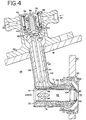
- the fuel element 16 of the main injector 10 and fuel element 18 of the pilot injector 12 extend through the combustor wall 20 and discharge into the combustor 22 of the turbine, as shown in FIG. 4.
- the fuel elements 16 and 18 are supported in the high pressure air plenum 24, as shown in FIG. 4, by a support stem 26 which extends from the air plenum wall 14 into the air plenum 24 and to the fuel elements.
- Fuel is supplied in a conventional manner from a fuel pump (not shown) under pressure to a flow control valve 28, as shown in FIG. 1. From the flow control valve 28 the fuel flows to two manifolds 30 and 32. Manifold 30 supplies the fuel to the main injector check valve 34 as shown by the solid lines in FIGS. 1-4. When the fuel pressure is low, such as during turbine idling, a check valve spring 36 will operate the check valve 34 to interrupt the fuel supply to the main injector. Fuel is also supplied from the manifold 32, as shown by the dotted lines in the drawing, to continuously flow to and through the housing of the check valve 34 to cool the housing, as will be explained in more detail to follow.
- This fuel will continuously flow from the housing of the check valve to the pilot injector 12 while the turbine is in operation, both during periods of low power requirements as well as high power requirements, will pass through the support stem 26 of the pilot injector 12, the fuel passages 38 in the fuel element 18 of the pilot injector 12, and will be discharged into the combustor of the gas turbine for combustion.
- the main injector check valve 34 includes a housing 40 which preferably is mounted, by a suitable flange 42, outside of the wall 14 of the air plenum 24.
- the housing 40 includes an annular chamber 44 to which the fuel for the pilot injector 12 is continuously supplied, as shown by the dotted arrows, through inlet 46, and is discharged to the pilot injector from the housing by an outlet 48, the latter of which is best seen in FIG. 2.
- the fuel discharged from the housing 40 then passes through a pilot injector check valve 50, as shown in FIG. 1, and to the pilot injector fuel element 18 and fuel passages 38 for discharge into the combustor during turbine operation.
- the pilot injector fuel which flows continuously through the annular chamber 44 while the turbine is in operation will cool the check valve 34 and its housing 40.
- the check valve 34 When the pressure of the fuel at the flow control valve 28 exceeds a predetermined level during periods of high power levels, this pressure will exceed the load of spring 36, and the check valve 34 will open to supply fuel to the main injector 10.
- the main injector fuel As shown by the solid arrows, the main injector fuel, as shown by the solid arrows, is communicated to the check valve 34 through inlet 52.
- the fuel When the fuel pressure exceeds a certain predetermined level during high power demand, the fuel will exert a sufficient pressure on the seat 54 of the valve 56 to cause the valve seat to move downwardly, as viewed in FIGS. 3 and 4, against the force of spring 36. When this occurs, fuel will flow to the main injector through the inlet 52 and filter screen 58, and will pass the valve seat 54, as shown by the solid arrows, to a chamber 60 beneath the valve 56.
- a trim orifice 62 is positioned at the top end of the support stem 26, as shown FIGS. 3 and 4, to meter the fuel to the support stem and its fuel element.
- the fuel passes through the trim orifice 62, as best seen in FIGS. 3 and 4, and is equally distributed to a pair of fuel conducting passages 64 and 66 which extend the length of the support stem, to conduct the fuel to the fuel element 16, again as shown by the solid arrows in the drawings.
- the fuel element 16 preferably comprises a cylindrical body which has at least a pair of discrete inlet chambers 68 and 70 milled or otherwise formed in its outer surface adjacent one end 72 of the fuel element.
- the inlet chambers 68 and 70 are shown in longitudinal alignment with each other in FIG. 4 for illustrative purposes only.
- the inlet chambers in practice preferably will be spaced from each other about the circumference of the fuel element 16, as best seen in FIG. 6.
- One of the fuel conducting passages 64 communicates the fuel from the trim orifice 62 to the inlet chamber 68, and the other fuel conducting passage 66 communicates the fuel to the other inlet chamber 70.
- the fuel will flow from the inlet chamber 68 to a first pair of fuel passages 74 and 76 which are also preferably milled or otherwise formed in the surface of the fuel element 16.
- the fuel passages 74 and 76 also preferably include a milled metering portion 78 at each of their ends adjacent the discharge orifices 80 from which the fuel is discharged into the combustor 22, as shown in FIG. 4.
- the metering portions 78 preferably approach the discharge end 82 of the fuel element in a tangential manner to impart a swirling motion to the fuel as it is discharged to enhance combustion of the fuel.
- the fuel also passes from the inlet chamber 70 to a second pair of fuel passages 84 and 86, as best seen in FIG. 6, which also include tangentially arranged metering portions 88 adjacent the discharge orifices 90 of the fuel passages 84 and 86 from which atomized fuel is discharged in a swirling fashion into the combustor 22.
- first fuel passages 74 and 76 and two second fuel passages 84 and 86 are shown and described, it will be understood that only single first and second fuel passages may be employed, as well as more than two of each of such passages without departing from the principles of the invention.
- the air channel 92 is positioned radially inwardly of the fuel passages 74, 76 and 84, 86 on the outer surface of the fuel element as shown in the drawings.
- An air swirler 94 is also preferably positioned in the air channel 92 to impart a swirling motion to the air.
- the injector 10 may be surrounded by one or more air dome caps 96 and 98, as shown in FIG. 4, to introduce additional swirling air to the combustor 22 together with the swirling fuel.
- a longitudinally extending sleeve 100 supports the fuel element 16.
- the sleeve 100 is preferably shrunk fit around the fuel element 16 so as to confine the fuel passages 74, 76, 84, 86 which are formed on the outer surface of the fuel element 16.
- the entire assembly is also preferably surrounded with one or more heat shields 102, as shown in FIG. 4, to protect the assembly against heat.
- a pair of very small air passages 104 are bored or drilled so that each extends radially between the air channel 92 and the respective first fuel passages 74 and 76 adjacent the discharge of the fuel from those first passages.
- the air passages 104 are positioned upstream of the metering portions 78 of the fuel passages.
- the metering portions 78 of the first fuel passages 74 and 76 may be spaced slightly upstream of the fuel discharge orifices 80, and the air passages 104 are positioned downstream of the metering portions 78 between the metering portions and the discharge orifices 80 of the first fuel passages 74 and 76.
- the second fuel passages 84 and 86 do not include such purging air passages.
- This higher pressure air will force the residual fuel in a reverse direction through the first air passages 74 and 76, the inlet chamber 68, the fuel conducting passage 64, the fuel conducting passage 66 which communicates with the fuel conducting passage 64 adjacent the trim orifice 62, the inlet chamber 70 and the second fuel passages 84 and 86, and this residual fuel will be discharged from the discharge orifices 90 of the second fuel passages into the combustor 22 for burning.
- the purging air will continue to flow through the assembly during main injector shut down and while the turbine continues to be operational to maintain the injector clear of fuel.
- the purging action of the present invention overcomes a number of disadvantages of the prior art purging systems. It is simple and eloquent in its construction, design and function, avoids the need for moving parts and for the combination and operation in unison of more than one injector, and avoids the need for at least a pair of injectors of differing construction.
- the purging of residual fuel in gas turbine combustor fuel injectors is disclosed in which the fuel injector includes a fuel element having a first and second fuel passage for discharging the fuel to the combustor of the gas turbine. Upon interruption of the fuel to the fuel element, high pressure air is passed through an air passage to the first fuel passage to force the fuel in the reverse direction through the first fuel passage, through the second fuel passage, and discharge the residual fuel in each of the passages to the combustor through the second fuel passage.
Landscapes
- Engineering & Computer Science (AREA)
- Chemical & Material Sciences (AREA)
- Combustion & Propulsion (AREA)
- Mechanical Engineering (AREA)
- General Engineering & Computer Science (AREA)
- Fuel-Injection Apparatus (AREA)
- Feeding And Controlling Fuel (AREA)
- Spray-Type Burners (AREA)
Applications Claiming Priority (2)
| Application Number | Priority Date | Filing Date | Title |
|---|---|---|---|
| US378025 | 1995-01-24 | ||
| US08/378,025 US5701732A (en) | 1995-01-24 | 1995-01-24 | Method and apparatus for purging of gas turbine injectors |
Publications (3)
| Publication Number | Publication Date |
|---|---|
| EP0724115A2 true EP0724115A2 (de) | 1996-07-31 |
| EP0724115A3 EP0724115A3 (de) | 1998-03-04 |
| EP0724115B1 EP0724115B1 (de) | 2001-11-14 |
Family
ID=23491425
Family Applications (1)
| Application Number | Title | Priority Date | Filing Date |
|---|---|---|---|
| EP96100918A Expired - Lifetime EP0724115B1 (de) | 1995-01-24 | 1996-01-23 | Reinigungsverfahren für Gasturbinen-Einspritzdüse |
Country Status (3)
| Country | Link |
|---|---|
| US (2) | US5701732A (de) |
| EP (1) | EP0724115B1 (de) |
| DE (2) | DE724115T1 (de) |
Cited By (8)
| Publication number | Priority date | Publication date | Assignee | Title |
|---|---|---|---|---|
| EP0939220A1 (de) * | 1998-02-26 | 1999-09-01 | Abb Research Ltd. | Verfahren zum sicheren Entfernen von Flüssigbrennstoff aus dem Brennstoffsystem einer Gasturbine sowie Vorrichtung zur Durchführung des Verfahrens |
| DE10123708A1 (de) * | 2001-05-15 | 2002-11-21 | Alstom Switzerland Ltd | Verfahren und Vorrichtung zur Spülung einer Brennstoffleitung in einer Gasturbinenanlage |
| DE10219354A1 (de) * | 2002-04-30 | 2003-11-13 | Rolls Royce Deutschland | Gasturbinenbrennkammer mit gezielter Kraftstoffeinbringung zur Verbesserung der Homogenität des Kraftstoff-Luft-Gemisches |
| GB2425171A (en) * | 2005-02-05 | 2006-10-18 | Alstom Technology Ltd | Fuel injection system purging including a fuel concentration sensor |
| US7527037B2 (en) | 2006-03-17 | 2009-05-05 | Rolls-Royce Plc | Component for fuel supply |
| US8015815B2 (en) | 2007-04-18 | 2011-09-13 | Parker-Hannifin Corporation | Fuel injector nozzles, with labyrinth grooves, for gas turbine engines |
| CN104373220A (zh) * | 2013-08-15 | 2015-02-25 | 西门子公司 | 用于燃气轮机的吹扫系统和方法 |
| US9033263B2 (en) | 2003-10-20 | 2015-05-19 | Rolls-Royce Deutschland Ltd & Co Kg | Fuel injection nozzle with film-type fuel application |
Families Citing this family (58)
| Publication number | Priority date | Publication date | Assignee | Title |
|---|---|---|---|---|
| CA2248736C (en) | 1996-03-13 | 2007-03-27 | Parker-Hannifin Corporation | Internally heatshielded nozzle |
| DE19653059A1 (de) * | 1996-12-19 | 1998-06-25 | Asea Brown Boveri | Verfahren zum Betrieb eines Brenners |
| US6125624A (en) * | 1998-04-17 | 2000-10-03 | Pratt & Whitney Canada Corp. | Anti-coking fuel injector purging device |
| US6145318A (en) * | 1998-10-22 | 2000-11-14 | General Electric Co. | Dual orifice bypass system for dual-fuel gas turbine |
| US6149075A (en) * | 1999-09-07 | 2000-11-21 | General Electric Company | Methods and apparatus for shielding heat from a fuel nozzle stem of fuel nozzle |
| US6536217B2 (en) | 2000-12-20 | 2003-03-25 | Honeywell Power Systems Inc. | Liquid fuel reverse purge |
| US6622488B2 (en) * | 2001-03-21 | 2003-09-23 | Parker-Hannifin Corporation | Pure airblast nozzle |
| US6543235B1 (en) | 2001-08-08 | 2003-04-08 | Cfd Research Corporation | Single-circuit fuel injector for gas turbine combustors |
| US6959535B2 (en) * | 2003-01-31 | 2005-11-01 | General Electric Company | Differential pressure induced purging fuel injectors |
| US6898926B2 (en) * | 2003-01-31 | 2005-05-31 | General Electric Company | Cooled purging fuel injectors |
| US20090217669A1 (en) * | 2003-02-05 | 2009-09-03 | Young Kenneth J | Fuel nozzles |
| GB0302721D0 (en) * | 2003-02-05 | 2003-03-12 | Rolls Royce Plc | Fuel nozzles |
| DE10340826A1 (de) * | 2003-09-04 | 2005-03-31 | Rolls-Royce Deutschland Ltd & Co Kg | Homogene Gemischbildung durch verdrallte Einspritzung des Kraftstoffs |
| US7174717B2 (en) * | 2003-12-24 | 2007-02-13 | Pratt & Whitney Canada Corp. | Helical channel fuel distributor and method |
| US7430851B2 (en) * | 2005-01-18 | 2008-10-07 | Parker-Hannifin Corporation | Air and fuel venting device for fuel injector nozzle tip |
| US7213394B2 (en) * | 2005-01-27 | 2007-05-08 | Cummins Inc. | Engine blowby injector and injection system and method for injecting blowby |
| US7677025B2 (en) * | 2005-02-01 | 2010-03-16 | Power Systems Mfg., Llc | Self-purging pilot fuel injection system |
| US7726112B2 (en) | 2006-04-24 | 2010-06-01 | Pratt & Whitney Canada Corp. | Fuel system of gas turbine engines |
| US7900456B2 (en) * | 2006-05-19 | 2011-03-08 | Delavan Inc | Apparatus and method to compensate for differential thermal growth of injector components |
| US8499739B2 (en) * | 2006-08-31 | 2013-08-06 | Caterpillar Inc. | Injector having tangentially oriented purge line |
| US8448881B2 (en) * | 2006-10-13 | 2013-05-28 | Rolls-Royce Power Engineering Plc | Fuel injector |
| US8215100B2 (en) * | 2007-03-02 | 2012-07-10 | Caterpillar Inc. | Regeneration device having external check valve |
| US7841184B2 (en) | 2007-04-19 | 2010-11-30 | Pratt & Whitney Canada Corp. | Start flow measurement |
| US7530260B2 (en) * | 2007-04-19 | 2009-05-12 | Pratt & Whitney Canada Corp. | Surge detection in a gas turbine engine |
| DE102007043626A1 (de) * | 2007-09-13 | 2009-03-19 | Rolls-Royce Deutschland Ltd & Co Kg | Gasturbinenmagerbrenner mit Kraftstoffdüse mit kontrollierter Kraftstoffinhomogenität |
| GB0800294D0 (en) * | 2008-01-09 | 2008-02-20 | Rolls Royce Plc | Gas heater |
| GB2457281B (en) * | 2008-02-11 | 2010-09-08 | Rolls Royce Plc | A Combustor Wall Arrangement with Parts Joined by Mechanical Fasteners |
| US7926282B2 (en) * | 2008-03-04 | 2011-04-19 | Delavan Inc | Pure air blast fuel injector |
| US9046039B2 (en) * | 2008-05-06 | 2015-06-02 | Rolls-Royce Plc | Staged pilots in pure airblast injectors for gas turbine engines |
| US8096135B2 (en) * | 2008-05-06 | 2012-01-17 | Dela Van Inc | Pure air blast fuel injector |
| GB2460634B (en) * | 2008-06-02 | 2010-07-07 | Rolls Royce Plc | Combustion apparatus |
| US8240150B2 (en) * | 2008-08-08 | 2012-08-14 | General Electric Company | Lean direct injection diffusion tip and related method |
| US8220269B2 (en) * | 2008-09-30 | 2012-07-17 | Alstom Technology Ltd. | Combustor for a gas turbine engine with effusion cooled baffle |
| US8220271B2 (en) * | 2008-09-30 | 2012-07-17 | Alstom Technology Ltd. | Fuel lance for a gas turbine engine including outer helical grooves |
| IT1392335B1 (it) * | 2008-12-19 | 2012-02-28 | Ansaldo Energia Spa | Metodo e dispositivo per pulire ugelli gasolio di un bruciatore |
| US8161750B2 (en) * | 2009-01-16 | 2012-04-24 | General Electric Company | Fuel nozzle for a turbomachine |
| US20110247590A1 (en) * | 2010-04-07 | 2011-10-13 | Delavan Inc | Injectors utilizing lattice support structure |
| CA2833205C (en) | 2010-12-30 | 2019-08-20 | Rolls-Royce Power Engineering Plc | Method and apparatus for isolating inactive fluid passages |
| US9360219B2 (en) * | 2010-12-30 | 2016-06-07 | Rolls-Royce North American Technologies, Inc. | Supercritical or mixed phase multi-port fuel injector |
| US9103285B2 (en) | 2011-01-03 | 2015-08-11 | General Electric Company | Purge system, system including a purge system, and purge method |
| US20120227408A1 (en) * | 2011-03-10 | 2012-09-13 | Delavan Inc. | Systems and methods of pressure drop control in fluid circuits through swirling flow mitigation |
| US8479492B2 (en) * | 2011-03-25 | 2013-07-09 | Pratt & Whitney Canada Corp. | Hybrid slinger combustion system |
| US20130199191A1 (en) * | 2011-06-10 | 2013-08-08 | Matthew D. Tyler | Fuel injector with increased feed area |
| US8984888B2 (en) * | 2011-10-26 | 2015-03-24 | General Electric Company | Fuel injection assembly for use in turbine engines and method of assembling same |
| US9377201B2 (en) * | 2013-02-08 | 2016-06-28 | Solar Turbines Incorporated | Forged fuel injector stem |
| GB201408058D0 (en) * | 2014-05-07 | 2014-06-18 | Rolls Royce Plc | A fuel manifold and fuel injector arrangement for a combustion chamber |
| US9765972B2 (en) | 2015-01-30 | 2017-09-19 | Delavan Inc. | Fuel injectors for gas turbine engines |
| US20170080361A1 (en) * | 2015-09-18 | 2017-03-23 | Delavan Inc | Strainers |
| EP3225915B1 (de) * | 2016-03-31 | 2019-02-06 | Rolls-Royce plc | Brenstoffinjektor und verfahren zur herstellung |
| US10907831B2 (en) | 2018-05-07 | 2021-02-02 | Rolls-Royce Corporation | Ram pressure recovery fuel nozzle with a scoop |
| FR3084449B1 (fr) * | 2018-07-25 | 2020-07-17 | Safran Aircraft Engines | Dispositif d'injection de carburant multipoint |
| US10967394B2 (en) | 2018-11-01 | 2021-04-06 | Rolls-Royce Corporation | Fluid atomizer |
| US11261791B2 (en) | 2019-02-25 | 2022-03-01 | Rolls-Royce Corporation | Hybrid propulsion cooling system |
| US11713723B2 (en) * | 2019-05-15 | 2023-08-01 | Pratt & Whitney Canada Corp. | Method and system for operating an engine |
| GB2592267A (en) * | 2020-02-24 | 2021-08-25 | Altair Uk Ltd | Pulse nozzle for filter cleaning systems |
| DE102021004141A1 (de) * | 2021-03-31 | 2022-10-06 | Mathias Herrmann | Angepasstes Verfahrenskonzept und Leistungskonzept für Triebwerke (z.B. Raketen, Überschallraketenbrennkammern / Düsentriebwerke), luftatmende Antriebe (z.B. Unterschall-Staustrahltriebwerke, Ramjets, Scramjets, Dualmode, Pulsejets, Detonationstriebwerke, Raketen-Staustrahl- Antriebe), Turbopumpen bzw. Düsen (z.B. Glockendüsen, Aerospikes) |
| US11592177B2 (en) | 2021-04-16 | 2023-02-28 | General Electric Company | Purging configuration for combustor mixing assembly |
| US12305581B2 (en) * | 2022-08-26 | 2025-05-20 | Collins Engine Nozzles, Inc. | Proportional restriction of a secondary circuit of a fuel injector |
Family Cites Families (8)
| Publication number | Priority date | Publication date | Assignee | Title |
|---|---|---|---|---|
| US3375978A (en) * | 1966-03-21 | 1968-04-02 | Rand Mines Ltd | Spray gun with self-purging nozzle |
| US4216652A (en) * | 1978-06-08 | 1980-08-12 | General Motors Corporation | Integrated, replaceable combustor swirler and fuel injector |
| US4984424A (en) * | 1988-02-16 | 1991-01-15 | Sundstrand Corporation | Fuel injection system for a turbine engine |
| US4856713A (en) * | 1988-08-04 | 1989-08-15 | Energy Conservation Innovations, Inc. | Dual-fuel injector |
| US5277023A (en) * | 1991-10-07 | 1994-01-11 | Fuel Systems Textron, Inc. | Self-sustaining fuel purging fuel injection system |
| US5329760A (en) * | 1991-10-07 | 1994-07-19 | Fuel Systems Textron, Inc. | Self-sustaining fuel purging fuel injection system |
| US5417054A (en) * | 1992-05-19 | 1995-05-23 | Fuel Systems Textron, Inc. | Fuel purging fuel injector |
| US5243816A (en) * | 1992-06-19 | 1993-09-14 | Fuel Systems Textron, Inc. | Self purging fuel injector |
-
1995
- 1995-01-24 US US08/378,025 patent/US5701732A/en not_active Expired - Lifetime
-
1996
- 1996-01-23 DE DE0724115T patent/DE724115T1/de active Pending
- 1996-01-23 EP EP96100918A patent/EP0724115B1/de not_active Expired - Lifetime
- 1996-01-23 DE DE69616841T patent/DE69616841T2/de not_active Expired - Lifetime
-
1997
- 1997-05-30 US US08/866,467 patent/US5799872A/en not_active Expired - Lifetime
Cited By (13)
| Publication number | Priority date | Publication date | Assignee | Title |
|---|---|---|---|---|
| EP0939220A1 (de) * | 1998-02-26 | 1999-09-01 | Abb Research Ltd. | Verfahren zum sicheren Entfernen von Flüssigbrennstoff aus dem Brennstoffsystem einer Gasturbine sowie Vorrichtung zur Durchführung des Verfahrens |
| US6256975B1 (en) | 1998-02-26 | 2001-07-10 | Abb Research Ltd. | Method for reliably removing liquid fuel from the fuel system of a gas turbine, and a device for carrying out the method |
| DE10123708A1 (de) * | 2001-05-15 | 2002-11-21 | Alstom Switzerland Ltd | Verfahren und Vorrichtung zur Spülung einer Brennstoffleitung in einer Gasturbinenanlage |
| DE10219354A1 (de) * | 2002-04-30 | 2003-11-13 | Rolls Royce Deutschland | Gasturbinenbrennkammer mit gezielter Kraftstoffeinbringung zur Verbesserung der Homogenität des Kraftstoff-Luft-Gemisches |
| US7086234B2 (en) | 2002-04-30 | 2006-08-08 | Rolls-Royce Deutschland Ltd & Co Kg | Gas turbine combustion chamber with defined fuel input for the improvement of the homogeneity of the fuel-air mixture |
| US9033263B2 (en) | 2003-10-20 | 2015-05-19 | Rolls-Royce Deutschland Ltd & Co Kg | Fuel injection nozzle with film-type fuel application |
| GB2425171B (en) * | 2005-02-05 | 2007-04-04 | Alstom Technology Ltd | Fuel injection system and purging method |
| US7818955B2 (en) | 2005-02-05 | 2010-10-26 | Alstom Technology Ltd | Fuel injection system and purging method |
| DE102006005130B4 (de) * | 2005-02-05 | 2015-03-19 | Alstom Technology Ltd. | Brennstoffeinspritzsystem und Verfahren zur Überwachung eines Brennstoffeinspritzsystems |
| GB2425171A (en) * | 2005-02-05 | 2006-10-18 | Alstom Technology Ltd | Fuel injection system purging including a fuel concentration sensor |
| US7527037B2 (en) | 2006-03-17 | 2009-05-05 | Rolls-Royce Plc | Component for fuel supply |
| US8015815B2 (en) | 2007-04-18 | 2011-09-13 | Parker-Hannifin Corporation | Fuel injector nozzles, with labyrinth grooves, for gas turbine engines |
| CN104373220A (zh) * | 2013-08-15 | 2015-02-25 | 西门子公司 | 用于燃气轮机的吹扫系统和方法 |
Also Published As
| Publication number | Publication date |
|---|---|
| US5701732A (en) | 1997-12-30 |
| DE69616841D1 (de) | 2001-12-20 |
| DE69616841T2 (de) | 2002-04-04 |
| EP0724115A3 (de) | 1998-03-04 |
| DE724115T1 (de) | 1997-04-03 |
| EP0724115B1 (de) | 2001-11-14 |
| US5799872A (en) | 1998-09-01 |
Similar Documents
| Publication | Publication Date | Title |
|---|---|---|
| US5701732A (en) | Method and apparatus for purging of gas turbine injectors | |
| US9046039B2 (en) | Staged pilots in pure airblast injectors for gas turbine engines | |
| EP1278014B1 (de) | Kraftstofffördervorrichtung | |
| EP1286111B1 (de) | Multiplex Einspritzdüse | |
| EP1271057B1 (de) | Gasturbinenbrennkammer | |
| US5881550A (en) | Staged fuel injection system with shuttle valve and fuel injector therefor | |
| US6073436A (en) | Fuel injector with purge passage | |
| EP1069377B1 (de) | Brennstoffablassvorrichtung für Brennstoffeinspritzdüse | |
| US6609380B2 (en) | Liquid fuel nozzle apparatus with passive protective purge | |
| EP2554905B1 (de) | Anordnungen und Vorrichtung im Zusammenhang mit der Integration später Magergemischeinspritzung in Turbinenverbrennungsmotoren | |
| US6622488B2 (en) | Pure airblast nozzle | |
| US5243816A (en) | Self purging fuel injector | |
| US6955040B1 (en) | Controlled pressure fuel nozzle injector | |
| US8096135B2 (en) | Pure air blast fuel injector | |
| US5277023A (en) | Self-sustaining fuel purging fuel injection system | |
| US8661824B2 (en) | Airblast fuel nozzle assembly | |
| US8099940B2 (en) | Low cross-talk gas turbine fuel injector | |
| EP3735560B1 (de) | Gasturbinenbrennkammer umfassend einen fackelzünder und brennstoffzuführungsverfahren für einen fackelzünder | |
| WO1994028357A1 (en) | A gas turbine engine combustion chamber | |
| EP2592351B1 (de) | Gestufte Pilotbrenner in reinen Drucklufteinspritzdüsen für Gasturbinenmotoren | |
| EP0822345B1 (de) | Vorrichtung zum Regeln des Brennstoff-Ablassstromes für eine Turbine mit Nachverbrennung | |
| US4562698A (en) | Variable area means for air systems of air blast type fuel nozzle assemblies | |
| EP1367329A4 (de) | Brenner und gasturbinenmotor | |
| US4967562A (en) | Turbine engine with high efficiency fuel atomization | |
| US11002196B2 (en) | Combustion chamber comprising two types of injectors in which the sealing members have a different opening threshold |
Legal Events
| Date | Code | Title | Description |
|---|---|---|---|
| PUAI | Public reference made under article 153(3) epc to a published international application that has entered the european phase |
Free format text: ORIGINAL CODE: 0009012 |
|
| AK | Designated contracting states |
Kind code of ref document: A2 Designated state(s): DE FR GB IT |
|
| RIN1 | Information on inventor provided before grant (corrected) |
Inventor name: SHOEMAKER, ROBERT D. Inventor name: NESBITT, GREGORY S. |
|
| ITCL | It: translation for ep claims filed |
Representative=s name: PROROGA X L.I. X MESI 6 29.4.97;JACOBACCI CASETTA |
|
| EL | Fr: translation of claims filed | ||
| DET | De: translation of patent claims | ||
| PUAL | Search report despatched |
Free format text: ORIGINAL CODE: 0009013 |
|
| AK | Designated contracting states |
Kind code of ref document: A3 Designated state(s): DE FR GB IT |
|
| 17P | Request for examination filed |
Effective date: 19980520 |
|
| 17Q | First examination report despatched |
Effective date: 20000306 |
|
| GRAG | Despatch of communication of intention to grant |
Free format text: ORIGINAL CODE: EPIDOS AGRA |
|
| GRAG | Despatch of communication of intention to grant |
Free format text: ORIGINAL CODE: EPIDOS AGRA |
|
| GRAH | Despatch of communication of intention to grant a patent |
Free format text: ORIGINAL CODE: EPIDOS IGRA |
|
| GRAH | Despatch of communication of intention to grant a patent |
Free format text: ORIGINAL CODE: EPIDOS IGRA |
|
| GRAA | (expected) grant |
Free format text: ORIGINAL CODE: 0009210 |
|
| AK | Designated contracting states |
Kind code of ref document: B1 Designated state(s): DE FR GB IT |
|
| REF | Corresponds to: |
Ref document number: 69616841 Country of ref document: DE Date of ref document: 20011220 |
|
| REG | Reference to a national code |
Ref country code: GB Ref legal event code: IF02 |
|
| ET | Fr: translation filed | ||
| PLBE | No opposition filed within time limit |
Free format text: ORIGINAL CODE: 0009261 |
|
| STAA | Information on the status of an ep patent application or granted ep patent |
Free format text: STATUS: NO OPPOSITION FILED WITHIN TIME LIMIT |
|
| 26N | No opposition filed | ||
| PGFP | Annual fee paid to national office [announced via postgrant information from national office to epo] |
Ref country code: IT Payment date: 20120124 Year of fee payment: 17 |
|
| REG | Reference to a national code |
Ref country code: FR Ref legal event code: PLFP Year of fee payment: 20 |
|
| PGFP | Annual fee paid to national office [announced via postgrant information from national office to epo] |
Ref country code: DE Payment date: 20150120 Year of fee payment: 20 |
|
| PGFP | Annual fee paid to national office [announced via postgrant information from national office to epo] |
Ref country code: GB Payment date: 20150121 Year of fee payment: 20 Ref country code: FR Payment date: 20150108 Year of fee payment: 20 |
|
| REG | Reference to a national code |
Ref country code: DE Ref legal event code: R071 Ref document number: 69616841 Country of ref document: DE |
|
| REG | Reference to a national code |
Ref country code: GB Ref legal event code: PE20 Expiry date: 20160122 |
|
| PG25 | Lapsed in a contracting state [announced via postgrant information from national office to epo] |
Ref country code: GB Free format text: LAPSE BECAUSE OF EXPIRATION OF PROTECTION Effective date: 20160122 |
|
| PG25 | Lapsed in a contracting state [announced via postgrant information from national office to epo] |
Ref country code: IT Free format text: LAPSE BECAUSE OF NON-PAYMENT OF DUE FEES Effective date: 20140123 |