EP0724116A2 - Garniture céramique - Google Patents
Garniture céramique Download PDFInfo
- Publication number
- EP0724116A2 EP0724116A2 EP96810022A EP96810022A EP0724116A2 EP 0724116 A2 EP0724116 A2 EP 0724116A2 EP 96810022 A EP96810022 A EP 96810022A EP 96810022 A EP96810022 A EP 96810022A EP 0724116 A2 EP0724116 A2 EP 0724116A2
- Authority
- EP
- European Patent Office
- Prior art keywords
- fastening element
- ceramic
- wall
- ceramic lining
- lining according
- Prior art date
- Legal status (The legal status is an assumption and is not a legal conclusion. Google has not performed a legal analysis and makes no representation as to the accuracy of the status listed.)
- Withdrawn
Links
Images


Classifications
-
- F—MECHANICAL ENGINEERING; LIGHTING; HEATING; WEAPONS; BLASTING
- F23—COMBUSTION APPARATUS; COMBUSTION PROCESSES
- F23M—CASINGS, LININGS, WALLS OR DOORS SPECIALLY ADAPTED FOR COMBUSTION CHAMBERS, e.g. FIREBRIDGES; DEVICES FOR DEFLECTING AIR, FLAMES OR COMBUSTION PRODUCTS IN COMBUSTION CHAMBERS; SAFETY ARRANGEMENTS SPECIALLY ADAPTED FOR COMBUSTION APPARATUS; DETAILS OF COMBUSTION CHAMBERS, NOT OTHERWISE PROVIDED FOR
- F23M5/00—Casings; Linings; Walls
- F23M5/04—Supports for linings
-
- F—MECHANICAL ENGINEERING; LIGHTING; HEATING; WEAPONS; BLASTING
- F23—COMBUSTION APPARATUS; COMBUSTION PROCESSES
- F23R—GENERATING COMBUSTION PRODUCTS OF HIGH PRESSURE OR HIGH VELOCITY, e.g. GAS-TURBINE COMBUSTION CHAMBERS
- F23R3/00—Continuous combustion chambers using liquid or gaseous fuel
- F23R3/007—Continuous combustion chambers using liquid or gaseous fuel constructed mainly of ceramic components
-
- F—MECHANICAL ENGINEERING; LIGHTING; HEATING; WEAPONS; BLASTING
- F27—FURNACES; KILNS; OVENS; RETORTS
- F27D—DETAILS OR ACCESSORIES OF FURNACES, KILNS, OVENS OR RETORTS, IN SO FAR AS THEY ARE OF KINDS OCCURRING IN MORE THAN ONE KIND OF FURNACE
- F27D1/00—Casings; Linings; Walls; Roofs
- F27D1/04—Casings; Linings; Walls; Roofs characterised by the form, e.g. shape of the bricks or blocks used
-
- F—MECHANICAL ENGINEERING; LIGHTING; HEATING; WEAPONS; BLASTING
- F27—FURNACES; KILNS; OVENS; RETORTS
- F27D—DETAILS OR ACCESSORIES OF FURNACES, KILNS, OVENS OR RETORTS, IN SO FAR AS THEY ARE OF KINDS OCCURRING IN MORE THAN ONE KIND OF FURNACE
- F27D1/00—Casings; Linings; Walls; Roofs
- F27D1/14—Supports for linings
- F27D1/145—Assembling elements
-
- F—MECHANICAL ENGINEERING; LIGHTING; HEATING; WEAPONS; BLASTING
- F23—COMBUSTION APPARATUS; COMBUSTION PROCESSES
- F23M—CASINGS, LININGS, WALLS OR DOORS SPECIALLY ADAPTED FOR COMBUSTION CHAMBERS, e.g. FIREBRIDGES; DEVICES FOR DEFLECTING AIR, FLAMES OR COMBUSTION PRODUCTS IN COMBUSTION CHAMBERS; SAFETY ARRANGEMENTS SPECIALLY ADAPTED FOR COMBUSTION APPARATUS; DETAILS OF COMBUSTION CHAMBERS, NOT OTHERWISE PROVIDED FOR
- F23M2900/00—Special features of, or arrangements for combustion chambers
- F23M2900/05004—Special materials for walls or lining
Definitions
- the invention relates to a ceramic lining for thermally highly stressed walls of combustion chambers, in particular combustion chambers for gas turbines, the lining consisting of individual elements which are fastened to the metallic wall by means of holding devices.
- the lining with refractory elements based on oxidic materials can be regarded as state of the art.
- these bricks In addition to the low mechanical stability and the thick-walled, heavy construction, these bricks have the disadvantage that the individual elements cannot be dismantled without being destroyed.
- the material properties of the oxidic materials used for these linings are not up to the increasing mechanical and thermal loads, for example in gas turbine combustion chambers.
- the high-temperature-resistant structural ceramics available today such as silicon carbide SiC and silicon nitride Si 3 N 4 , are not suitable for use in industrial combustion chambers as linings with a form-fitting structure made up of individual elements without a fixed connection of the parts.
- the invention tries to avoid all these disadvantages. It is based on the task of creating an uncooled, releasable lining of a combustion chamber with ceramic elements, which can withstand the high mechanical and thermal stresses in a commercial, highly stressed combustion chamber.
- a ceramic lining for combustion chambers consisting of at least one wall plate made of high-temperature-resistant structural ceramic with at least one through opening and of one fastening element per opening, the fastening element being fastened with its foot in a metallic holding device fastened to the metallic supporting wall is and the head of the fastening element rests in the opening of the wall plate, and wherein an insulation layer is arranged between the metallic wall and the ceramic wall plate, the fastening element made of high-temperature-resistant structural ceramics is resiliently connected to the holding device.
- the advantages of the invention can be seen, inter alia, in the fact that the lining can withstand very high mechanical and thermal stresses due to its homogeneity and the material used, that the lining can be disassembled without destruction and can therefore be used repeatedly and that due to the spring-elastic connection of the ceramic structure to the metal holding structure, the thermal expansions between metallic and ceramic components or deformations of the insulation layer are absorbed by mechanical stresses.
- the fastening element has a shape which is optimized from a thermal point of view, preferably an arch in the middle of the head, one rounded head and rounded cross-sectional transitions with large radii from head to shaft and from shaft to foot. This ensures that the mechanical and thermal stresses cause only low stresses.
- the shaft of the fastening element is surrounded by a divided sleeve made of solidified, preformed insulation material and the contact surfaces to the metal in the region of the foot of the fastening element are also provided with an insulating layer. This leads to a minimization of the temperature gradient within the ceramic fastening element, so that the thermal stresses can be kept at a low level.
- the wall plate is drawn in in the area of the opening in the direction of the metallic supporting wall, so that the head of the fastening element is completely received by the opening in the ceramic wall plate.
- the insulation layer consists of ceramic fiber material, which can be applied in the form of prefabricated blocks.
- the insulation layer is advantageously solidified at least in the region of the butt joint of the adjacent wall panels or is otherwise protected on the surface. This prevents the insulation from being flushed out in the case of parasitic hot air flows in the gap.
- the insulation layer has a bore in the area of the fastening element to be received.
- the metallic holding device consists of a longitudinally divided threaded sleeve, which comprises the foot of the fastening element, with one on the external thread the sleeve seated nut, and a guide ring embedded in the metallic wall, a guide sleeve and spring elements.
- a reliable, removable and easily adjustable connection between the base of the ceramic fastening element and the metallic parts is thereby achieved.
- a seal is advantageously arranged between the guide sleeve and the guide ring. This prevents possible leakage air flows that could occur due to the generally positive pressure drop between the outer, cooling air side and the inner, hot gas side of the lining.
- FIG. 1 shows a partial longitudinal section of the lining according to the invention for a gas turbine combustion chamber.
- An insulation layer 2 is applied to the metallic support wall 1 of the combustion chamber.
- This preferably consists of ceramic fiber material.
- the wall plates 3 and the insulation layer 2 are fastened to the metal supporting wall 1 with the aid of fastening elements 4, which are each arranged in a metallic holding device 5, which will be described in detail later.
- these fastening elements 4 also consist of high-temperature-resistant structural ceramics.
- the outer shape and the dimensions of the wall panels 3 can be easily adapted to the geometry of the room to be lined and are in no way predetermined.
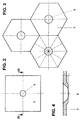
- the wall panels 3 shows a further possible shape of the wall panels 3.
- they have a hexagonal outer contour.
- symmetrical shapes are preferred.
- the thickness d of the wall plate 3 results on the one hand from the required mechanical stability and on the other hand from minimizing the thermal stresses due to temperature gradients in the component.
- a through opening 6 for receiving a fastening element 4, which here is a bolt consisting of head, shaft and foot.
- a fastening element 4 which here is a bolt consisting of head, shaft and foot.
- a plurality of openings 6 can also be present in each wall plate 3.
- FIG. 4 which shows an enlarged section of the wall plate 3 according to FIG. 2 in the region of the opening 6 along the line IV-IV, the opening 6 is drawn in in the direction of the metallic supporting wall 1.
- this increases the contact area between the fastening element 4 and the wall plate 3, and on the other hand the heat flows in the case of stationary and unsteady load gradients are influenced in such a way that only minimal thermal stresses arise.
- the geometric design of this zone results from a coordination between the heat storage and heat conduction properties of the materials used.
- a ratio of the thickness d of the wall plate 3 to the depth t of the drawn-in part of the wall plate 3 in the region of the opening 6 of approximately 5 to 3 has proven to be advantageous.
- the contact surface between the head of the fastening element 4 (not shown in FIG. 4) arranged in the opening 6 and the wall plate 3 is optimally spherical in order to ensure a flat contact even with small angular positions of the bolt (ball head principle).
- the head of the fastening element 4 is also spherical, as can be seen in FIGS. 5a and 5b, which each show a longitudinal section of two differently designed fastening elements 4.
- the foot of the fastening element 4 is also spherical, which is then received by a correspondingly designed threaded sleeve 7 of the metal holding device 5. Since the metal / ceramic contact surface at the foot of the fastening element 4 is also spherical, a flat contact is also ensured here even at small angular positions.
- fastening element 4 which is optimized in terms of thermal technology, is that the head of the fastening element 4 has a bulge 8 in its center.
- large radii and moderate cross-section transitions are used, so that basic rules for designing with brittle ceramic materials are observed.
- the cavity between the shaft of the fastening element 4 and the insulation layer 2 is filled by a split sleeve 15 made of solidified, preformed insulation material. Since the contact surfaces to the metal in the area of the foot of the fastening element 4 are also provided with an insulating intermediate layer, the temperature gradients within the fastening element 4 are minimized and the thermal stresses are kept at a low level.
- the thickness of the insulation layer 2 is selected in accordance with the thermal load on the overall composite of the lining. It is to be determined in such a way that the maximum permissible temperatures of the metal supporting wall 1 are not exceeded.
- the insulation material can be applied, for example, in the form of prefabricated blocks, a corresponding hole having to be provided in the area of the fastening bolt 4 for the assembly of the lining. Since the mounting distance between two wall plates 3 is determined by the thermal expansions of the wall plates 3, it is at least in the range underneath the butt joints of two adjacent plate elements, the surface of the insulation material is suitably solidified or otherwise protected, so that the insulation layer 2 is avoided in the gap in the case of parasitic hot air flows.
- a central point of the invention is the stretch-tolerant elastic clamping of the ceramic fastening element 4 on the outside of the metal supporting wall 1.
- the metallic holding device 5 consists of a longitudinally divided threaded sleeve 7, which comprises the foot of the fastening element.
- a threaded nut 9 is arranged, via which, as will be explained further below, the clamping force can be adjusted.
- the nut 9 holds the two halves of the threaded sleeve 7 together.
- the mutual positioning of the two threaded sleeve halves can be achieved by additional construction elements, e.g. the bolts.
- a square 10 serves to hold the split sleeve when tightening the threaded nut 9. Positions 7 and 10 are part of the split sleeve.
- the metallic holding device 5 consists of a guide ring 11 embedded in the metallic supporting wall 1, a one-piece guide sleeve 12 for the fastening element 4 and spring elements 13 arranged between the guide sleeve 12 and the guide ring 11.
- the spring 13 is, for example, as in FIG. 1 shown a disc spring.
- the spring-elastic connection of the ceramic structure to the metallic holding device ensures that thermal relative expansions between the metallic and ceramic components or deformations of the insulation layer 2 ("setting") are absorbed by mechanical stresses, for example pulsations in the combustion chamber, without the contact surfaces impermissibly high voltages in the ceramic component can be induced. Almost constant clamping forces are ensured via a certain spring travel of the clamping (adjustable via the threaded nut 9 screwed onto the external thread of the sleeve 7).
- a seal 14 is arranged against possible leakage air flows.
- This seal 14 is located between the guide sleeve 12 and the guide ring 11 embedded in the metallic support wall 1. The play in the guide also allows a certain angular position of the bolt without additional forces being introduced into the bolt.
Landscapes
- Engineering & Computer Science (AREA)
- Mechanical Engineering (AREA)
- General Engineering & Computer Science (AREA)
- Chemical & Material Sciences (AREA)
- Combustion & Propulsion (AREA)
- Ceramic Engineering (AREA)
- Connection Of Plates (AREA)
- Furnace Housings, Linings, Walls, And Ceilings (AREA)
Applications Claiming Priority (2)
| Application Number | Priority Date | Filing Date | Title |
|---|---|---|---|
| DE19502730A DE19502730A1 (de) | 1995-01-28 | 1995-01-28 | Keramische Auskleidung |
| DE19502730 | 1995-01-28 |
Publications (2)
| Publication Number | Publication Date |
|---|---|
| EP0724116A2 true EP0724116A2 (fr) | 1996-07-31 |
| EP0724116A3 EP0724116A3 (fr) | 1997-12-03 |
Family
ID=7752579
Family Applications (1)
| Application Number | Title | Priority Date | Filing Date |
|---|---|---|---|
| EP96810022A Withdrawn EP0724116A3 (fr) | 1995-01-28 | 1996-01-10 | Garniture céramique |
Country Status (4)
| Country | Link |
|---|---|
| US (1) | US5624256A (fr) |
| EP (1) | EP0724116A3 (fr) |
| JP (1) | JPH08296976A (fr) |
| DE (1) | DE19502730A1 (fr) |
Cited By (16)
| Publication number | Priority date | Publication date | Assignee | Title |
|---|---|---|---|---|
| EP0895028A1 (fr) * | 1997-07-28 | 1999-02-03 | Abb Research Ltd. | Garniture céramique |
| EP0895027A1 (fr) * | 1997-07-28 | 1999-02-03 | Abb Research Ltd. | Garniture céramique |
| DE19825546C1 (de) * | 1998-06-08 | 1999-08-26 | Didier Werke Ag | Einrichtung zum Befestigen von Auskleidungsplatten |
| WO1999047874A1 (fr) * | 1998-03-19 | 1999-09-23 | Siemens Aktiengesellschaft | Segment de paroi pour une chambre de combustion, et chambre de combustion |
| EP1072573A1 (fr) | 1999-07-30 | 2001-01-31 | Siemens Aktiengesellschaft | Procédé de fabrication d'une pièce réfractaire et brique céramique de chambre de combustion |
| EP1126221A1 (fr) | 2000-02-17 | 2001-08-22 | Siemens Aktiengesellschaft | Tuile réfractaire rembourrée pour révêtement d'une chambre de combustion de turbies à gaz |
| EP1191285A1 (fr) | 2000-09-22 | 2002-03-27 | Siemens Aktiengesellschaft | Bouclier thérmique , chambre de combustion avec garnissage interne et turbine à gaz |
| DE10046094A1 (de) * | 2000-09-18 | 2002-05-02 | Siemens Ag | Hitzeschildstein zur Auskleidung einer Brennkammerwand, Brennkammer sowie Gasturbine |
| EP1712840A1 (fr) * | 2005-04-13 | 2006-10-18 | Siemens Aktiengesellschaft | Bouclier thermique avec boulon de fixation |
| EP1862740A1 (fr) * | 2006-05-31 | 2007-12-05 | Siemens Aktiengesellschaft | Paroi de chambre de combustion |
| EP1710501A3 (fr) * | 1999-11-06 | 2008-01-23 | Rolls-Royce plc | Eléments de paroi pour turbomachine |
| US7540710B2 (en) | 2003-10-27 | 2009-06-02 | Siemens Aktiengesellschaft | Turbine blade for use in a gas turbine |
| US7793503B2 (en) | 2003-08-22 | 2010-09-14 | Siemens Aktiengesellschaft | Heat shield block for lining a combustion chamber wall, combustion chamber and gas turbine |
| WO2010105709A2 (fr) | 2009-03-17 | 2010-09-23 | Siemens Aktiengesellschaft | Élément de protection thermique d'un bouclier thermique |
| US7942007B2 (en) | 2005-04-19 | 2011-05-17 | Siemens Aktiengesellschaft | Heat shield element for lining a combustion chamber wall, combustion chamber and gas turbine |
| CH703656A1 (de) * | 2010-08-27 | 2012-02-29 | Alstom Technology Ltd | Von Heissgasen durchströmbarer Gehäusekörper mit innerem Hitzeschild. |
Families Citing this family (27)
| Publication number | Priority date | Publication date | Assignee | Title |
|---|---|---|---|---|
| DE19623300A1 (de) * | 1996-06-11 | 1997-12-18 | Siemens Ag | Hitzeschildanordnung, insbesondere für Strukturteile von Gasturbinenanlagen, mit geschichtetem Aufbau |
| DE29613515U1 (de) * | 1996-08-03 | 1997-12-04 | GfT Gesellschaft für Feuerfest-Technik mbH, 47441 Moers | Anordnung zur Verminderung der Gaserosion und -korrosion von Feuerfest-Systemen |
| JP2942254B2 (ja) * | 1997-10-27 | 1999-08-30 | タキ産業株式会社 | 高温炉内張り用セラミックファイバブロック |
| DE19748259A1 (de) * | 1997-10-31 | 1999-05-06 | Bosch Gmbh Robert | Brennkammer für Warmwasserbereiter, insbesondere Gasheizgeräte |
| DE59806717D1 (de) | 1998-03-17 | 2003-01-30 | Alstom Switzerland Ltd | Keramische Auskleidung einer Brennkammer |
| EP1006315B1 (fr) | 1998-11-30 | 2004-01-21 | ALSTOM (Switzerland) Ltd | Garnissage céramique d'une chambre de combustion |
| DE19927491A1 (de) * | 1999-06-16 | 2000-12-21 | Kalenborn Kalprotect Dr Maurit | Auskleidungsplattenbefestigung |
| JP4747443B2 (ja) * | 2001-06-21 | 2011-08-17 | Jfeスチール株式会社 | ベンチュリ・スクラバー |
| EP1288601B1 (fr) * | 2001-08-28 | 2006-10-25 | Siemens Aktiengesellschaft | Brique de protection thermique ainsi que son utilisation dans une chambre de combustion |
| DE10154285A1 (de) * | 2001-11-05 | 2003-05-15 | Rolls Royce Deutschland | Hitzeschildanordnung mit kragenförmigem Befestigungsbereich |
| EP1389714A1 (fr) * | 2002-08-16 | 2004-02-18 | Siemens Aktiengesellschaft | Chambre à combustion de turbine à gaz |
| EP1533572A1 (fr) * | 2003-11-24 | 2005-05-25 | Siemens Aktiengesellschaft | Chambre de combustion pour turbine à gaz et turbine à gaz |
| DE102006060857B4 (de) | 2006-12-22 | 2014-02-13 | Deutsches Zentrum für Luft- und Raumfahrt e.V. | CMC-Brennkammerauskleidung in Doppelschichtbauweise |
| US8771604B2 (en) * | 2007-02-06 | 2014-07-08 | Aerojet Rocketdyne Of De, Inc. | Gasifier liner |
| DE102007062699A1 (de) | 2007-12-27 | 2009-07-02 | Rolls-Royce Deutschland Ltd & Co Kg | Brennkammerauskleidung |
| EP2270395B1 (fr) * | 2009-06-09 | 2015-01-14 | Siemens Aktiengesellschaft | Agencement d'élément de bouclier thermique et procédé de montage d'un élément de bouclier thermique |
| DE102011075865A1 (de) * | 2011-05-16 | 2012-11-22 | Siemens Aktiengesellschaft | Brennkammerseitig verschraubte Brennereinsatzplatte |
| US9422865B2 (en) * | 2013-03-14 | 2016-08-23 | Rolls-Royce Corporation | Bi-metal fastener for thermal growth compensation |
| WO2015009384A1 (fr) * | 2013-07-16 | 2015-01-22 | United Technologies Corporation | Turbine à gaz pourvue d'un panneau en céramique |
| US10451280B2 (en) * | 2015-02-16 | 2019-10-22 | United Technologies Corporation | Combustor panel having material transition region |
| EP3104079B1 (fr) * | 2015-06-08 | 2018-10-31 | ANSALDO ENERGIA S.p.A. | Chambres de combustion de turbines à gaz ayant un dispositif d'ancrage de boucliers thermiques |
| US10767863B2 (en) * | 2015-07-22 | 2020-09-08 | Rolls-Royce North American Technologies, Inc. | Combustor tile with monolithic inserts |
| GB2540769A (en) * | 2015-07-27 | 2017-02-01 | Rolls Royce Plc | Combustor for a gas turbine engine |
| DE102015217161A1 (de) * | 2015-09-04 | 2017-03-09 | Rolls-Royce Deutschland Ltd & Co Kg | Baugruppe mit einer Brennkammerschindel für eine Gasturbine |
| DE102016211613A1 (de) | 2016-06-28 | 2017-12-28 | Siemens Aktiengesellschaft | Hitzeschildanordnung einer Brennkammer mit Tellerfederpaket |
| US10969106B2 (en) * | 2019-08-13 | 2021-04-06 | General Electric Company | Axial retention assembly for combustor components of a gas turbine engine |
| US20240230234A9 (en) * | 2022-10-24 | 2024-07-11 | HarbisonWalker International Holdings, Inc. | Apparatus and method for preventing lining disruptions exposed to elevated temperature |
Family Cites Families (15)
| Publication number | Priority date | Publication date | Assignee | Title |
|---|---|---|---|---|
| US377172A (en) * | 1888-01-31 | Heel-nailing machine | ||
| DE1932881C3 (de) * | 1969-06-28 | 1978-06-29 | Motoren- Und Turbinen-Union Muenchen Gmbh, 8000 Muenchen | Brennkammer für Gasturbinentriebwerke |
| US4242948A (en) * | 1977-12-16 | 1981-01-06 | Cummins Engine Company, Inc. | Insulated composite piston |
| GB1568603A (en) * | 1977-01-15 | 1980-06-04 | Carborundum Co Ltd | Furnace linings |
| US4139975A (en) * | 1977-06-29 | 1979-02-20 | Baker Edward S | Universal retainer assembly |
| JPS5832136Y2 (ja) * | 1979-02-02 | 1983-07-16 | 日本碍子株式会社 | セラミツクフアイバ−を内張材とする窯炉 |
| US4748806A (en) * | 1985-07-03 | 1988-06-07 | United Technologies Corporation | Attachment means |
| EP0224817B1 (fr) * | 1985-12-02 | 1989-07-12 | Siemens Aktiengesellschaft | Ecran de protection contre la chaleur pour éléments structuraux d'une turbine à gaz |
| DE3625056C2 (de) * | 1986-07-24 | 1997-05-28 | Siemens Ag | Feuerfeste Auskleidung, insbesondere für Brennkammern von Gasturbinenanlagen |
| AU594814B2 (en) * | 1986-09-13 | 1990-03-15 | Foseco International Limited | Furnaces |
| DD279896A1 (de) * | 1989-02-06 | 1990-06-20 | Freiberg Brennstoffinst | Generator zur festbettdruckvergasung mit schnellgranulierung der asche |
| JPH0762594B2 (ja) * | 1989-08-11 | 1995-07-05 | 日本碍子株式会社 | ファイバー炉 |
| DE4314160A1 (de) * | 1992-05-13 | 1993-11-18 | Siemens Ag | Fügeverbindung und Verfahren zu ihrer Herstellung |
| US5265411A (en) * | 1992-10-05 | 1993-11-30 | United Technologies Corporation | Attachment clip |
| US5333443A (en) * | 1993-02-08 | 1994-08-02 | General Electric Company | Seal assembly |
-
1995
- 1995-01-28 DE DE19502730A patent/DE19502730A1/de not_active Withdrawn
-
1996
- 1996-01-10 EP EP96810022A patent/EP0724116A3/fr not_active Withdrawn
- 1996-01-17 US US08/586,159 patent/US5624256A/en not_active Expired - Fee Related
- 1996-01-26 JP JP8011867A patent/JPH08296976A/ja not_active Abandoned
Cited By (34)
| Publication number | Priority date | Publication date | Assignee | Title |
|---|---|---|---|---|
| EP0895027A1 (fr) * | 1997-07-28 | 1999-02-03 | Abb Research Ltd. | Garniture céramique |
| US5957067A (en) * | 1997-07-28 | 1999-09-28 | Abb Research Ltd. | Ceramic liner |
| US6145452A (en) * | 1997-07-28 | 2000-11-14 | Abb Research Ltd. | Ceramic lining |
| EP0895028A1 (fr) * | 1997-07-28 | 1999-02-03 | Abb Research Ltd. | Garniture céramique |
| US6612248B2 (en) | 1998-03-19 | 2003-09-02 | Siemens Aktiengesellschaft | Wall segment for a combustion area, and a combustion area |
| WO1999047874A1 (fr) * | 1998-03-19 | 1999-09-23 | Siemens Aktiengesellschaft | Segment de paroi pour une chambre de combustion, et chambre de combustion |
| US6397765B1 (en) | 1998-03-19 | 2002-06-04 | Siemens Aktiengesellschaft | Wall segment for a combustion chamber and a combustion chamber |
| DE19825546C1 (de) * | 1998-06-08 | 1999-08-26 | Didier Werke Ag | Einrichtung zum Befestigen von Auskleidungsplatten |
| EP1072573A1 (fr) | 1999-07-30 | 2001-01-31 | Siemens Aktiengesellschaft | Procédé de fabrication d'une pièce réfractaire et brique céramique de chambre de combustion |
| EP1710501A3 (fr) * | 1999-11-06 | 2008-01-23 | Rolls-Royce plc | Eléments de paroi pour turbomachine |
| EP1126221A1 (fr) | 2000-02-17 | 2001-08-22 | Siemens Aktiengesellschaft | Tuile réfractaire rembourrée pour révêtement d'une chambre de combustion de turbies à gaz |
| WO2001061250A1 (fr) | 2000-02-17 | 2001-08-23 | Siemens Aktiengesellschaft | Pierre de protection thermique et dispositif de garniture d'une paroi de chambre de combustion et turbine a gaz |
| DE10046094A1 (de) * | 2000-09-18 | 2002-05-02 | Siemens Ag | Hitzeschildstein zur Auskleidung einer Brennkammerwand, Brennkammer sowie Gasturbine |
| DE10046094C2 (de) * | 2000-09-18 | 2002-09-19 | Siemens Ag | Hitzeschildstein zur Auskleidung einer Brennkammerwand |
| US6832484B2 (en) | 2000-09-22 | 2004-12-21 | Siemens Aktiengesellschaft | Heat-shield brick, combustion chamber comprising an internal, combustion chamber lining and a gas turbine |
| EP1191285A1 (fr) | 2000-09-22 | 2002-03-27 | Siemens Aktiengesellschaft | Bouclier thérmique , chambre de combustion avec garnissage interne et turbine à gaz |
| US7793503B2 (en) | 2003-08-22 | 2010-09-14 | Siemens Aktiengesellschaft | Heat shield block for lining a combustion chamber wall, combustion chamber and gas turbine |
| US8857190B2 (en) | 2003-10-27 | 2014-10-14 | Siemens Aktiengesellschaft | Heat shield element, in particular for lining a combustion chamber wall |
| US7805945B2 (en) | 2003-10-27 | 2010-10-05 | Siemens Aktiengesellschaft | Thermal shield, especially for lining the wall of a combustion chamber |
| US7540710B2 (en) | 2003-10-27 | 2009-06-02 | Siemens Aktiengesellschaft | Turbine blade for use in a gas turbine |
| EP1712840A1 (fr) * | 2005-04-13 | 2006-10-18 | Siemens Aktiengesellschaft | Bouclier thermique avec boulon de fixation |
| US7942007B2 (en) | 2005-04-19 | 2011-05-17 | Siemens Aktiengesellschaft | Heat shield element for lining a combustion chamber wall, combustion chamber and gas turbine |
| WO2007137883A1 (fr) * | 2006-05-31 | 2007-12-06 | Siemens Aktiengesellschaft | Paroi de chambre de combustion |
| US8069670B2 (en) | 2006-05-31 | 2011-12-06 | Siemens Aktiengesellschaft | Combustion chamber wall |
| RU2437034C2 (ru) * | 2006-05-31 | 2011-12-20 | Сименс Акциенгезелльшафт | Стенка камеры сгорания и газовая турбина |
| EP1862740A1 (fr) * | 2006-05-31 | 2007-12-05 | Siemens Aktiengesellschaft | Paroi de chambre de combustion |
| WO2010105709A2 (fr) | 2009-03-17 | 2010-09-23 | Siemens Aktiengesellschaft | Élément de protection thermique d'un bouclier thermique |
| WO2010105709A3 (fr) * | 2009-03-17 | 2011-04-14 | Siemens Aktiengesellschaft | Élément de protection thermique d'un bouclier thermique |
| CN102356277A (zh) * | 2009-03-17 | 2012-02-15 | 西门子公司 | 热屏装置的热屏元件 |
| RU2515692C2 (ru) * | 2009-03-17 | 2014-05-20 | Сименс Акциенгезелльшафт | Элемент теплозащитного экрана |
| CN102356277B (zh) * | 2009-03-17 | 2014-10-22 | 西门子公司 | 热屏元件和热屏以及组装热屏元件的方法和热屏的应用 |
| CH703656A1 (de) * | 2010-08-27 | 2012-02-29 | Alstom Technology Ltd | Von Heissgasen durchströmbarer Gehäusekörper mit innerem Hitzeschild. |
| DE102011110660A1 (de) | 2010-08-27 | 2012-03-15 | Alstom Technology Ltd. | Von Heissgasen durchströmbarer Gehäusekörper mit innerem Hitzeschild |
| US9810154B2 (en) | 2010-08-27 | 2017-11-07 | Ansaldo Energia Ip Uk Limited | Casing body through which hot gases can flow and comprising an inner heat shield |
Also Published As
| Publication number | Publication date |
|---|---|
| JPH08296976A (ja) | 1996-11-12 |
| US5624256A (en) | 1997-04-29 |
| EP0724116A3 (fr) | 1997-12-03 |
| DE19502730A1 (de) | 1996-08-01 |
Similar Documents
| Publication | Publication Date | Title |
|---|---|---|
| EP0724116A2 (fr) | Garniture céramique | |
| EP0895027B1 (fr) | Garniture céramique | |
| EP0895028B1 (fr) | Garniture céramique | |
| EP0904512B1 (fr) | Systeme de bouclier thermique, notamment pour elements structuraux d'installations a turbine a gaz | |
| EP1006315B1 (fr) | Garnissage céramique d'une chambre de combustion | |
| DE19858197A1 (de) | Triebwerk | |
| EP1741981A1 (fr) | Bouclier thermique en céramique et réacteur à gaz hautes températures recouvert d'un tel bouclier | |
| DE2820174A1 (de) | Rohr oder behaelter mit innenauskleidung | |
| DE19730751A1 (de) | Keramisches Bauteil für eine Wärmeschutzschicht sowie Wärmeschutzschicht | |
| DE68910656T2 (de) | Demontierbare Verbindung zwischen zwei stark beanspruchten Teilen. | |
| DE19635292C2 (de) | Hitzebeständige Schutzblöcke und Schutzwandstruktur mit solchen Schutzblöcken für einen Kessel | |
| DE69914926T2 (de) | Ofenauskleidung | |
| DE2848570C2 (de) | Verschlußplatte für Heißwindschieber | |
| DE2757903A1 (de) | Befestigungsmittel zum befestigen einer isolierung an einer flaeche | |
| DE4430265B4 (de) | Verteilerschurre zum Einbau in einen Ofen | |
| DE2615041B2 (de) | Absperrklappe für einen heiße Gase, insbesondere Rauchgase, führenden Kanal | |
| DE19731382A1 (de) | Gaswechselventil und Verfahren zum Messen des Druckes in einem Brennraum einer Brennkraftmaschine | |
| CH399075A (de) | Brennkammer, insbesondere für magnetogasdynamische Maschinen | |
| EP2784421B1 (fr) | Brique de voûte pour le revêtement intérieur cylindrique d'un four rotatif et four rotatif | |
| EP1817528A1 (fr) | Element ecran thermique, son procede de production, revetement gaz chaud et chambre de combustion | |
| DE604659C (de) | Drehrohrofen | |
| EP1128131A1 (fr) | Bouclier thermique, chambre de combustion et turbine à gaz | |
| DE3717497C2 (de) | Kuppel für Gitterschacht und/oder Brennschacht eines Winderhitzers | |
| DE2116093C3 (de) | Vorrichtung zum Aufhängen von zweiteiligen kermischen Seinen | |
| DE1508191C (de) | Stichlochblock fur Sauerstoff Aufblas konverter |
Legal Events
| Date | Code | Title | Description |
|---|---|---|---|
| PUAI | Public reference made under article 153(3) epc to a published international application that has entered the european phase |
Free format text: ORIGINAL CODE: 0009012 |
|
| AK | Designated contracting states |
Kind code of ref document: A2 Designated state(s): DE GB IT |
|
| RAP1 | Party data changed (applicant data changed or rights of an application transferred) |
Owner name: ASEA BROWN BOVERI AG |
|
| PUAL | Search report despatched |
Free format text: ORIGINAL CODE: 0009013 |
|
| RHK1 | Main classification (correction) |
Ipc: F23R 3/00 |
|
| AK | Designated contracting states |
Kind code of ref document: A3 Designated state(s): DE GB IT |
|
| STAA | Information on the status of an ep patent application or granted ep patent |
Free format text: STATUS: THE APPLICATION IS DEEMED TO BE WITHDRAWN |
|
| 18D | Application deemed to be withdrawn |
Effective date: 19980604 |