EP0724206A2 - Soupape de régulation de pression - Google Patents
Soupape de régulation de pression Download PDFInfo
- Publication number
- EP0724206A2 EP0724206A2 EP95115299A EP95115299A EP0724206A2 EP 0724206 A2 EP0724206 A2 EP 0724206A2 EP 95115299 A EP95115299 A EP 95115299A EP 95115299 A EP95115299 A EP 95115299A EP 0724206 A2 EP0724206 A2 EP 0724206A2
- Authority
- EP
- European Patent Office
- Prior art keywords
- pressure
- control valve
- negative pressure
- pressure control
- membrane
- Prior art date
- Legal status (The legal status is an assumption and is not a legal conclusion. Google has not performed a legal analysis and makes no representation as to the accuracy of the status listed.)
- Withdrawn
Links
- 230000001105 regulatory effect Effects 0.000 title description 4
- 239000012528 membrane Substances 0.000 claims description 32
- 230000037431 insertion Effects 0.000 claims 1
- 238000003780 insertion Methods 0.000 claims 1
- 239000011324 bead Substances 0.000 description 4
- 238000002485 combustion reaction Methods 0.000 description 4
- 238000000034 method Methods 0.000 description 4
- 239000000203 mixture Substances 0.000 description 2
- 239000000725 suspension Substances 0.000 description 2
- 238000010276 construction Methods 0.000 description 1
- 238000007789 sealing Methods 0.000 description 1
Images

Classifications
-
- F—MECHANICAL ENGINEERING; LIGHTING; HEATING; WEAPONS; BLASTING
- F01—MACHINES OR ENGINES IN GENERAL; ENGINE PLANTS IN GENERAL; STEAM ENGINES
- F01M—LUBRICATING OF MACHINES OR ENGINES IN GENERAL; LUBRICATING INTERNAL COMBUSTION ENGINES; CRANKCASE VENTILATING
- F01M13/00—Crankcase ventilating or breathing
- F01M13/02—Crankcase ventilating or breathing by means of additional source of positive or negative pressure
- F01M13/021—Crankcase ventilating or breathing by means of additional source of positive or negative pressure of negative pressure
- F01M13/022—Crankcase ventilating or breathing by means of additional source of positive or negative pressure of negative pressure using engine inlet suction
- F01M13/023—Control valves in suction conduit
-
- G—PHYSICS
- G05—CONTROLLING; REGULATING
- G05D—SYSTEMS FOR CONTROLLING OR REGULATING NON-ELECTRIC VARIABLES
- G05D16/00—Control of fluid pressure
- G05D16/04—Control of fluid pressure without auxiliary power
- G05D16/06—Control of fluid pressure without auxiliary power the sensing element being a flexible membrane, yielding to pressure, e.g. diaphragm, bellows, capsule
- G05D16/063—Control of fluid pressure without auxiliary power the sensing element being a flexible membrane, yielding to pressure, e.g. diaphragm, bellows, capsule the sensing element being a membrane
- G05D16/0644—Control of fluid pressure without auxiliary power the sensing element being a flexible membrane, yielding to pressure, e.g. diaphragm, bellows, capsule the sensing element being a membrane the membrane acting directly on the obturator
- G05D16/0672—Control of fluid pressure without auxiliary power the sensing element being a flexible membrane, yielding to pressure, e.g. diaphragm, bellows, capsule the sensing element being a membrane the membrane acting directly on the obturator using several spring-loaded membranes
Definitions
- the invention relates to a pressure control valve, in particular for setting a negative pressure in a crankcase of a motor vehicle, according to the preamble of claim 1.
- Pressure control valves of the generic type are known. These are used, for example, to set / regulate a negative pressure in a crankcase of a motor vehicle. This negative pressure is necessary because, during the intended use of the crankcase, a leakage occurs between the piston ring and the cylinder wall due to the pistons moving within a cylinder block. This leak leads to a pressure build-up with a fuel-air mixture within the crankcase, which must be reduced. So that this build-up pressure does not go outdoors can escape, it is known to apply a negative pressure to the crankcase, by means of which the fuel-air mixture entering the crankcase can be drawn off and returned to the combustion process of the internal combustion engine.
- the pressure control valves have a connection which can be acted upon by vacuum and a connection which can be connected to the crankcase as the pressure space, a closing body which can be actuated by means of a control membrane separating or connecting the connection which can be acted upon by vacuum and the connection which can be connected to the pressure space.
- the control membrane is designed so that it opens due to a pressure building up in the crankcase and thus opens a valve seat interacting with the closing body, so that the vacuum can evacuate the crankcase. After evacuation of the crankcase, the closing body is forced to close the valve seat again by the negative pressure. The closing body is moved against the force of an elastic element.
- the elastic spring element must have such a large spring force that even with low negative pressure in the crankcase and high negative pressure applied by the negative pressure source, a secure opening of the valve seat is ensured .
- this relatively large spring force in turn hinders the closing process of the pressure control valve, since the spring force is overcome by the negative pressure of the negative pressure source got to. It is disadvantageous here that, due to a relatively slow closing process, a negative pressure which is established in the crankcase becomes too great, or the negative pressure which is established in the crankcase is subject to strong fluctuations.
- the pressure control valve according to the invention with the features mentioned in claim 1 offers the advantage that a constant setting of a vacuum in a pressure chamber is possible regardless of the level of the vacuum applied to the connection that can be connected to the vacuum source. Because the control diaphragm is assigned a pressure compensating element for the negative pressure, the pressure applied or established in the pressure chamber does not have to be activated by an additional spring force of an elastic element to open the valve seat or overcome the pressure to actuate the control diaphragm and thus to open the valve seat Negative pressure are supported. The spring force of the elastic element can now be kept to a minimum, so that the closing process of the pressure control valve takes place much faster by means of the negative pressure applied by the negative pressure source.
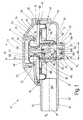
- FIG. 1 shows a sectional view through a pressure control valve, generally designated 10.
- the pressure control valve has a first housing part 12 and a second housing part 14.
- the housing parts 12 and 14 are designed in a manner to be explained as the lower and upper part of the pressure control valve 10.
- the housing part 12 has a tubular extension 16 which forms a connection 18 for a pressure chamber, for example a crankcase of an internal combustion engine, not shown.
- the extension 16 has on its outer circumference 20 a corrugation 22 which is suitable for fastening a flexible connection, for example a hose.
- the housing part 12 also has an opening 24 which is encompassed by an annular collar 26.
- the collar 26 has on its outer circumference a circumferential groove 28 into which a sealing ring 30 can be inserted.
- the collar 26 forms a connection 32 for a connection leading to a vacuum source, not shown, for example an intake manifold of a motor vehicle.
- the housing part 14 is essentially circular and has a circumferential annular groove 36 on its outer edge 34 facing the housing part 12.
- the groove 36 is formed by a shorter leg 38 and a longer leg 40 of the edge 34.
- the housing parts 12 and 14 can, for example, be connected to one another by a latching connection 42 in a manner not to be explained in more detail here.
- the housing part 14 has a sleeve-shaped section 46 which extends coaxially with an axial 44 and which can be closed by means of a cover cap 48.
- the cap 48 has at least a locking lug 50 which can be snapped into a corresponding recess 52 in the sleeve 46.
- the sleeve 46 has an annular collar 54 which forms a circumferential groove 56.
- the housing part 14 also has at least one through opening 58 which connects an interior space 60 with the atmosphere surrounding the pressure control valve 10, that is to say with normal pressure.
- a valve body 62 is located in the interior 60 of the pressure control valve 10.
- the valve body 62 has a sleeve-shaped section 64 which merges into an end section 66.
- the end section 66 has a truncated conical surface 68 which is constricted by a circumferential groove 70.
- the end section 66 also has an axial through opening 72 which opens into an interior 74 of the sleeve-shaped section 64. On the other hand, the through opening 72 opens into an interior 76 of the housing part 14, which can be closed by the cover cap 48.
- the valve body 62 is held by means of a control membrane 78.
- the control membrane 78 has a profiling which, on the one hand, engages in a circumferential groove 80 of the valve body 62 and extends along the sleeve-shaped section 64.
- the control diaphragm 78 is reinforced or stabilized by a diaphragm plate 82, which is formed by a sleeve 84 which surrounds the sleeve-shaped section 64 of the valve body 62.
- An intermediate space 86 located between the sleeve 84 and the sleeve-shaped section 64 of the valve body 62, which is, for example, on a Circular bores arranged through holes can be formed by the sleeve 84 is filled by an axially extending section 88 of the control membrane 78.
- the section 88 of the control membrane 78 is extended beyond the valve body 62 and forms a bead 90 there, which is supported on an inner surface 92 of the housing part 12.
- the control membrane 78 is clamped between the housing parts 12 and 14 in that the control membrane has a circumferential section 94 which comes to rest in the groove 36 of the housing part 14 and is locked by the leg 38.
- the valve body 62 is thus suspended freely by means of the control membrane 78 in the interior 60 of the pressure control valve 10.
- the suspension of the valve body 62 is designed in the idle state of the pressure control valve so that the bead 90 does not touch the inner surface 92, so that there is a direct connection between the connection 32 and the connection 18.
- the bead 90 and the inner surface 92 here form a valve seat 96 to be explained.
- An elastic spring element 100 is supported on a base 98 of the interior 74 of the sleeve-shaped section 64 and is mounted on a counter bearing 102.
- the counter bearing 102 is formed, for example, by cantilever arms 104 projecting into the connection 32.
- the cantilever arms 104 have a central through opening 106.
- the cantilever arms are designed in such a way that the smallest possible cross-sectional constriction occurs for the connection 32.
- the valve body 62 In the unloaded state of the elastic spring element 100, the valve body 62 is in such a position that the Valve seat 96 is open.
- the elastic spring element 100 thus supports the load-bearing action of the control membrane 78 for the valve element 62.
- a spring element (not shown in FIG. 1) can also be provided, which surrounds the sleeve 84.
- An auxiliary diaphragm 110 acts on the valve body 62, which is supported on the one hand in the groove 70 and on the other hand is clamped in the groove 56 of the housing part 14 by means of the cover cap 48.
- An active surface 112 of the auxiliary membrane 110 corresponds to a surface 114 of the valve body 62 which faces the connection 32.
- the arrangement of the valve body 62 divides the interior 60 of the pressure control valve 10 into different areas, of which a first area 116 is acted upon by normal pressure via the passage opening 58.
- This normal pressure is thus - according to the illustration shown in Figure 1 - on the top of the control membrane 78 and the bottom of the auxiliary membrane 110.
- a second area 118 or 119 which is formed by the interior 74 (118) of the valve body 62 and the interior 76 (119), which are connected to one another via the passage opening 72, the negative pressure present at the connection 32 is present.
- a third area 120 has the pressure level applied to the connection 18, which is also applied to the underside of the control membrane 78.
- the pressure control valve 10 shown in FIG. 1 performs the following function: When operating a motor vehicle equipped with the pressure control valve 10, the connection 18 is connected to the crankcase of the internal combustion engine.
- the connection 32 is simultaneously connected to a vacuum source, that is to say, in the case of a motor vehicle, for example to an intake manifold.
- the vacuum source provides a vacuum P U that can fluctuate between values from approx. -100 mbar to -900 mbar. Since the pressure control valve is in its initial position, that is, the valve seat 96 is slightly opened by the force of the spring element 100 or its elastic suspension in the control membrane 78, the negative pressure P U prevailing in the region 114 is via the opened valve seat by means of the negative pressure source 96 transferred to the area 120.
- This vacuum P U thus acts on the crankcase connected to the connection 18, so that it is evacuated and a certain vacuum P K (crankcase pressure) is established there.
- the negative pressure P K in the crankcase should be adjusted to a constant, slight negative pressure of, for example, -10 to -15 mbar.
- the negative pressure P U is simultaneously present on the valve body 62, namely on its surface 114 facing the connection 32. As a result, the valve body 62 is pulled against the force of the spring element 100 in the direction of the connection 32. On the other hand, acts on the valve body 62 via the control membrane 78 on the underside thereof the pressure P K applied to the region 120.
- the force emanating from the vacuum P U must be greater than the sum of the spring element 100 and the forces P K acting on the valve body 62. It is thus clear that to close the valve seat itself, the force exerted on the valve body 62 from the negative pressure P U must be greater than the force of the spring element 100, the force due to the rigidity of the membrane (especially at low temperatures) plus, or at a negative pressure P K minus, the force emanating from the pressure P K.
- a characteristic curve for regulating the pressure P K in the crankcase according to the prior art is shown by way of example in FIG. It is clear that with a fluctuating negative pressure P U, which for example can assume the values down to -900 mbar, the pressure P K ranges from approximately 5 mbar to can fluctuate around -30 mbar. This therefore has a relatively large bandwidth, which opposes the constant, low vacuum of, for example, -15 mbar in the crankcase.
- FIG. 1 The construction of the pressure control valve 10 according to the invention shown in FIG. 1 shows that the vacuum P U present at the connection 32 is simultaneously present in the region 119 formed by the interior space 76 through the through opening 72 of the valve body 62.
- the negative pressure P U acts here on the upper side of the auxiliary membrane 110. Since the auxiliary membrane 110 is firmly anchored with the valve body 62 in its groove 70, a force generated on the upper side of the auxiliary membrane 110 due to the negative pressure P U is transmitted to the valve body 62.
- the force emanating from the vacuum P U is therefore present on the opposite sides of the valve body 62, so that a choice of the size of the opposing surfaces which can be acted upon by the vacuum P U and exert a force on the valve body 62 resulting force is set, which acts on the valve body 62. If the active surface 112 of the auxiliary membrane 110 is now the same size as the surface 114, the valve body 62 is in a force equilibrium with respect to the force originating from the negative pressure P U , that is to say the resulting force has a value of zero.
- a pressure compensator for the valve body 62 is created through the passage opening 72, which connects the regions 116 and 118 to one another.
- the valve body 62 can thus have a position within the pressure control valve 10 occupy, which is independent of a negative pressure P U applied to the connection 32 and thus independent of a force exerted on the valve body 62 from the negative pressure P U.
- the resulting force F can be shifted into the positive or negative range, that is, the valve body 62 is - due to the negative pressure P U - either downwards, as shown in FIG. 1 or pulled up.
- the resulting force ideally has the value zero.
- the force opening or closing the valve seat 96 is determined exclusively by a force of the spring element 100 and a force emanating from the pressure P K in the region 120. It is thus possible to adjust the force emanating from the spring element 100 in such a way that a pressure P K of, for example, -15 mbar acting in the region 120, which is applied to the underside of the control membrane 78, is sufficient to counter the force of the spring element 100 to move so that the valve seat 96 closes. Even a slight increase in the pressure P K in the region 120 above the set value means that the force emanating from the slightly increased pressure P K is added to the force of the spring element 100, so that the valve body 62 is raised and thus the valve seat 96 opens.
- the open valve seat 96 is thus located at the connection 32 applied vacuum P U also in your area 120 so that the crankcase applied to the connection 18 can be evacuated. If this evacuation causes the pressure P K in the region 120 to drop to the preset value of, for example, -15 mbar, this is sufficient to overcome the force of the spring element 100, so that the valve body 62 is moved in the direction of the connection 32 and so that the valve seat 96 closes again.
- a pressure P K is set in the region 120, which fluctuates between the values from approx. -5 to approx. -20 mbar.
- the bandwidth is reduced, that is, the pressure fluctuations in the crankcase approx. 50 %.
- a much more precise setting of a certain, constant, defined pressure P K within the crankcase of, for example, -15 mbar is thus possible.
- the invention is not limited to the illustrated embodiment. in particular, further arrangements are conceivable, which allow the valve body 62 or the valve seat 96 to be designed in such a way that the pressure control valve 10 is regulated independently of the vacuum.
- the control behavior of the pressure control valve 10 can be easily achieved by dimensioning the spring element 100; the stronger this is dimensioned, the slower the valve seat 96 closes, and the active surface 112 of the control membrane 10 and the surface 114 of the valve body 62 are adjusted.
- the vacuum independence can be designed such that there is only an extremely low dependency on the vacuum P U. Fluctuations in the negative pressure P U during the intended use of the pressure control valve 10 can therefore exert little or no influence on the control behavior of the pressure control valve 10, so that overall it is possible to maintain a constant, as low as possible negative pressure P K in the crankcase.
Landscapes
- Engineering & Computer Science (AREA)
- Physics & Mathematics (AREA)
- Fluid Mechanics (AREA)
- General Physics & Mathematics (AREA)
- Automation & Control Theory (AREA)
- Mechanical Engineering (AREA)
- General Engineering & Computer Science (AREA)
- Safety Valves (AREA)
Applications Claiming Priority (2)
| Application Number | Priority Date | Filing Date | Title |
|---|---|---|---|
| DE19501447 | 1995-01-19 | ||
| DE1995101447 DE19501447A1 (de) | 1995-01-19 | 1995-01-19 | Druckregelventil |
Publications (2)
| Publication Number | Publication Date |
|---|---|
| EP0724206A2 true EP0724206A2 (fr) | 1996-07-31 |
| EP0724206A3 EP0724206A3 (fr) | 1997-08-20 |
Family
ID=7751807
Family Applications (1)
| Application Number | Title | Priority Date | Filing Date |
|---|---|---|---|
| EP95115299A Withdrawn EP0724206A3 (fr) | 1995-01-19 | 1995-09-28 | Soupape de régulation de pression |
Country Status (2)
| Country | Link |
|---|---|
| EP (1) | EP0724206A3 (fr) |
| DE (1) | DE19501447A1 (fr) |
Cited By (4)
| Publication number | Priority date | Publication date | Assignee | Title |
|---|---|---|---|---|
| WO2002073009A1 (fr) * | 2001-03-13 | 2002-09-19 | Volvo Lastvagnar Ab | Dispositif a soupapes pour commande de pression dans un moteur a combustion et procede de commande de pression |
| FR2826691A1 (fr) | 2001-07-02 | 2003-01-03 | Solvay | Circuit de reaspiration des gaz de carter d'un moteur a combustion interne |
| DE202008008035U1 (de) | 2008-06-16 | 2008-09-18 | Reinz-Dichtungs-Gmbh | Adaptives Saugunterdruck-kompensierendes Druckregelventil mit variablem Schaltpunkt |
| DE102008028543B3 (de) * | 2008-06-16 | 2009-10-08 | Reinz-Dichtungs-Gmbh | Adaptives Druckregelventil mit variablem Schaltpunkt |
Families Citing this family (7)
| Publication number | Priority date | Publication date | Assignee | Title |
|---|---|---|---|---|
| DE10061306A1 (de) | 2000-12-08 | 2002-07-11 | Mann & Hummel Filter | Druckregelventil mit einer druckbeaufschlagten Membran |
| DE20115847U1 (de) | 2001-09-26 | 2001-12-13 | Loctite Deutschland GmbH, 81925 München | Vorrichtung zur Ventilbetätigung und zum Stellen des Ventilhubs |
| DE10249720A1 (de) | 2002-10-25 | 2004-05-06 | Robert Bosch Gmbh | Druckregelventil |
| DE10337689B4 (de) * | 2003-08-16 | 2005-10-13 | Dieter Schulz | Konstantdruckventil, Verfahren zum Absperren eines Volumenstromes durch ein solches Konstantdruckventil und Verwendung eines Konstantdruckventiles |
| DE102008030134A1 (de) | 2007-08-07 | 2009-02-19 | Dichtungstechnik G. Bruss Gmbh & Co. Kg | Druckregelventil |
| DE102013019885B4 (de) * | 2013-11-28 | 2021-02-04 | Mann+Hummel Gmbh | Druckregelventil |
| DE102020208393B3 (de) | 2020-07-03 | 2021-11-04 | Mtu Friedrichshafen Gmbh | Druckregeleinrichtung für die Regelung eines Kurbelgehäusedrucks einer Brennkraftmaschine und Brennkraftmaschine mit einer solchen Druckregeleinrichtung |
Family Cites Families (6)
| Publication number | Priority date | Publication date | Assignee | Title |
|---|---|---|---|---|
| GB662741A (en) * | 1948-10-06 | 1951-12-12 | Evered & Co Ltd | Improvements relating to fluid pressure governors |
| US3263660A (en) * | 1964-06-17 | 1966-08-02 | Gen Motors Corp | Pressure regulator |
| US3262436A (en) * | 1964-12-08 | 1966-07-26 | Gen Motors Corp | Pressure regulating device |
| GB2078341A (en) * | 1980-06-18 | 1982-01-06 | Crosweller & Co Ltd W | A gas pressure governor |
| DE3611869A1 (de) * | 1986-04-09 | 1987-10-22 | Ruhrgas Ag | Regler, insbesondere fuer gasmotoren |
| DE4022129A1 (de) * | 1990-07-11 | 1992-01-16 | Mann & Hummel Filter | Druckregelventil fuer den einbau in eine entlueftungsleitung an einer brennkraftmaschine |
-
1995
- 1995-01-19 DE DE1995101447 patent/DE19501447A1/de not_active Withdrawn
- 1995-09-28 EP EP95115299A patent/EP0724206A3/fr not_active Withdrawn
Non-Patent Citations (1)
| Title |
|---|
| None |
Cited By (6)
| Publication number | Priority date | Publication date | Assignee | Title |
|---|---|---|---|---|
| WO2002073009A1 (fr) * | 2001-03-13 | 2002-09-19 | Volvo Lastvagnar Ab | Dispositif a soupapes pour commande de pression dans un moteur a combustion et procede de commande de pression |
| US6802303B2 (en) | 2001-03-13 | 2004-10-12 | Volvo Lastvagnar Ab | Valve device for pressure control in a combustion engine, and a method for such pressure control |
| FR2826691A1 (fr) | 2001-07-02 | 2003-01-03 | Solvay | Circuit de reaspiration des gaz de carter d'un moteur a combustion interne |
| DE202008008035U1 (de) | 2008-06-16 | 2008-09-18 | Reinz-Dichtungs-Gmbh | Adaptives Saugunterdruck-kompensierendes Druckregelventil mit variablem Schaltpunkt |
| DE102008028543B3 (de) * | 2008-06-16 | 2009-10-08 | Reinz-Dichtungs-Gmbh | Adaptives Druckregelventil mit variablem Schaltpunkt |
| US8297264B2 (en) | 2008-06-16 | 2012-10-30 | Reinz-Dichtungs-Gmbh | Adaptive pressure control valve with variable switching point |
Also Published As
| Publication number | Publication date |
|---|---|
| DE19501447A1 (de) | 1996-07-25 |
| EP0724206A3 (fr) | 1997-08-20 |
Similar Documents
| Publication | Publication Date | Title |
|---|---|---|
| EP0845077B1 (fr) | Dispositif d'injection de carburant pour moteurs a combustion interne | |
| EP0471142A2 (fr) | Soupape de réglage de la pression pour l'installation dans un conduit de purge d'un moteur à combustion interne | |
| EP1772618A1 (fr) | Injecteur à rampe commune | |
| EP1020936B1 (fr) | Organe de réglage comportant un actionneur à longueur réglable | |
| EP0724206A2 (fr) | Soupape de régulation de pression | |
| EP1321661B1 (fr) | Soupape d'injection de combustible pour moteurs à combustion interne | |
| WO2007017033A1 (fr) | Soupape de regulation de pression pneumatique | |
| DE112022005660T5 (de) | Stossdämpfer | |
| DE112022001586T5 (de) | Ventil und stossdämpfer | |
| DE10162045B4 (de) | Vorrichtung zum Übersetzen einer Auslenkung eines Aktors, insbesondere für ein Einspritzventil | |
| DE2830738C3 (de) | Pneumatisch betätigte Verstellvorrichtung | |
| EP1828593A1 (fr) | Soupape d'injection de carburant pour moteur a combustion interne | |
| DE69900474T2 (de) | Brennstoffpulsationsdämpfer mit vakuumgesteuerter vorspannung | |
| EP0802470B1 (fr) | Soupape de régulation de pression | |
| DE20016214U1 (de) | Drosselventil zur selbsttätigen Regelung des Drucks im Kurbelgehäuse einer Brennkraftmaschine | |
| DE102018207287A1 (de) | Ventilanordnung zur Gasdruckregelung, Kraftstoffsystem mit Ventilanordnung zur Gasdruckregelung | |
| EP1402174B1 (fr) | Dispositif d'injection de carburant pour moteur a combustion interne | |
| DE2348865A1 (de) | Vorrichtung zur brennstoffeinspritzung | |
| EP1518049A1 (fr) | Soupape d'injection de carburant pour moteurs a combustion interne | |
| DE19954288A1 (de) | Kraftstoffeinspritzventil für Brennkraftmaschinen | |
| EP0193142A1 (fr) | Dispositif de frein moteur pour moteur à combustion interne | |
| DE19654782C1 (de) | Einspritzinjektor für Dieselmotoren | |
| DE19912249C2 (de) | Ventil für eine Milchleitung | |
| DE2712511A1 (de) | Membrangeraet | |
| EP0198166B1 (fr) | Dispositif de correction pneumatique à membrane pour une pompe d'injection de combustible des moteurs à combustion interne |
Legal Events
| Date | Code | Title | Description |
|---|---|---|---|
| PUAI | Public reference made under article 153(3) epc to a published international application that has entered the european phase |
Free format text: ORIGINAL CODE: 0009012 |
|
| AK | Designated contracting states |
Kind code of ref document: A2 Designated state(s): DE FR GB IT |
|
| PUAL | Search report despatched |
Free format text: ORIGINAL CODE: 0009013 |
|
| AK | Designated contracting states |
Kind code of ref document: A3 Designated state(s): DE FR GB IT |
|
| STAA | Information on the status of an ep patent application or granted ep patent |
Free format text: STATUS: THE APPLICATION IS DEEMED TO BE WITHDRAWN |
|
| 18D | Application deemed to be withdrawn |
Effective date: 19980331 |