EP0724268A1 - Moteur électrique linéaire avec méthode d'analyse sensorielle - Google Patents
Moteur électrique linéaire avec méthode d'analyse sensorielle Download PDFInfo
- Publication number
- EP0724268A1 EP0724268A1 EP95116646A EP95116646A EP0724268A1 EP 0724268 A1 EP0724268 A1 EP 0724268A1 EP 95116646 A EP95116646 A EP 95116646A EP 95116646 A EP95116646 A EP 95116646A EP 0724268 A1 EP0724268 A1 EP 0724268A1
- Authority
- EP
- European Patent Office
- Prior art keywords
- sensor
- groove
- anchoring
- linear drive
- section
- Prior art date
- Legal status (The legal status is an assumption and is not a legal conclusion. Google has not performed a legal analysis and makes no representation as to the accuracy of the status listed.)
- Granted
Links
- 238000004873 anchoring Methods 0.000 claims abstract description 116
- 230000007704 transition Effects 0.000 claims description 9
- 230000015572 biosynthetic process Effects 0.000 claims 1
- 238000010276 construction Methods 0.000 description 2
- 239000000463 material Substances 0.000 description 2
- 235000014676 Phragmites communis Nutrition 0.000 description 1
- XAGFODPZIPBFFR-UHFFFAOYSA-N aluminium Chemical compound [Al] XAGFODPZIPBFFR-UHFFFAOYSA-N 0.000 description 1
- 229910052782 aluminium Inorganic materials 0.000 description 1
- 239000004020 conductor Substances 0.000 description 1
- 238000011161 development Methods 0.000 description 1
- 230000018109 developmental process Effects 0.000 description 1
- 230000000694 effects Effects 0.000 description 1
- 239000012530 fluid Substances 0.000 description 1
- 230000001939 inductive effect Effects 0.000 description 1
- 238000009413 insulation Methods 0.000 description 1
- 238000007789 sealing Methods 0.000 description 1
Images
Classifications
-
- F—MECHANICAL ENGINEERING; LIGHTING; HEATING; WEAPONS; BLASTING
- F15—FLUID-PRESSURE ACTUATORS; HYDRAULICS OR PNEUMATICS IN GENERAL
- F15B—SYSTEMS ACTING BY MEANS OF FLUIDS IN GENERAL; FLUID-PRESSURE ACTUATORS, e.g. SERVOMOTORS; DETAILS OF FLUID-PRESSURE SYSTEMS, NOT OTHERWISE PROVIDED FOR
- F15B15/00—Fluid-actuated devices for displacing a member from one position to another; Gearing associated therewith
- F15B15/20—Other details, e.g. assembly with regulating devices
- F15B15/28—Means for indicating the position, e.g. end of stroke
- F15B15/2892—Means for indicating the position, e.g. end of stroke characterised by the attachment means
-
- B—PERFORMING OPERATIONS; TRANSPORTING
- B23—MACHINE TOOLS; METAL-WORKING NOT OTHERWISE PROVIDED FOR
- B23Q—DETAILS, COMPONENTS, OR ACCESSORIES FOR MACHINE TOOLS, e.g. ARRANGEMENTS FOR COPYING OR CONTROLLING; MACHINE TOOLS IN GENERAL CHARACTERISED BY THE CONSTRUCTION OF PARTICULAR DETAILS OR COMPONENTS; COMBINATIONS OR ASSOCIATIONS OF METAL-WORKING MACHINES, NOT DIRECTED TO A PARTICULAR RESULT
- B23Q17/00—Arrangements for observing, indicating or measuring on machine tools
- B23Q17/22—Arrangements for observing, indicating or measuring on machine tools for indicating or measuring existing or desired position of tool or work
-
- H—ELECTRICITY
- H02—GENERATION; CONVERSION OR DISTRIBUTION OF ELECTRIC POWER
- H02B—BOARDS, SUBSTATIONS OR SWITCHING ARRANGEMENTS FOR THE SUPPLY OR DISTRIBUTION OF ELECTRIC POWER
- H02B1/00—Frameworks, boards, panels, desks, casings; Details of substations or switching arrangements
- H02B1/015—Boards, panels, desks; Parts thereof or accessories therefor
- H02B1/04—Mounting thereon of switches or of other devices in general, the switch or device having, or being without, casing
Definitions
- the invention relates to a linear drive, with a housing which has at least one longitudinal anchoring groove on its outer surface, which is used for sensor attachment, and which has a slot neck and an anchoring section which is deeper than the slot neck and wider than this, with a sensor fixed in the anchoring slot is received with a fastening section in the anchoring section, and a sensor cable serving to transmit sensor signals goes out from the sensor.
- a linear drive of this type can be seen, for example, from German utility model G 94 14 869.4.
- an anchoring groove which extends in the longitudinal direction and is open on the longitudinal side and which has a narrower groove neck and, adjoining it in the depth direction, a wider anchoring section.
- Sensors can be detachably fixed in the anchoring groove, which in the fixed state have a fastening section in the anchoring section protrude into it.
- a cable exit point from where a sensor cable leads, which can be connected to a control device.
- the sensor responds to a magnetic device integrated in the piston of the linear drive, which results in certain sensor signals. These are processed by the control device and can be used, for example, to control the operating mode of the linear drive.
- DE 39 23 063 C2 has already proposed removing the signal cables entirely and transmitting the sensor signals via conductor tracks integrated in the housing of the linear drive.
- this requires, above all on the electrical side, increased structural outlay, which is associated with an increase in the price of the product, which cannot be tolerated in all applications.
- the cross-sectional design of the anchoring section of the anchoring groove and the fastening section of the sensor are coordinated with one another such that when the sensor is fixed, at least one longitudinal cable duct is present between the fastening section and the wall of the anchoring section, with the simultaneous definition of several Sensors in the anchoring groove at least one sensor cable laid in the anchoring groove is passed through at least one further sensor.
- sensor cables of several other sensors can be passed through at the same time.
- several cable feed-through channels can be specified in the area of the respective sensor, which enable several sensor channels to be guided past the sensor in question independently of one another. It is currently considered to be particularly advantageous to assign two cable feed-through channels to a respective sensor, that flank the sensor in question on opposite longitudinal sides, in particular in the region of the groove flanks.
- the cable exit point for the signal cable of the sensor is located within the anchoring groove when the sensor is fixed, there is basically the possibility of the signal cable being completely sunk into the housing of the linear drive.
- the anchoring groove has a special cross-sectional contour.
- This can preferably be characterized in that a longitudinal longitudinal recess is formed in at least one of the transition areas between the groove flanks and the groove base of the anchoring groove, in the manner of a fillet.
- the cross-sectional contour of this longitudinal recess is preferably rounded off in a concave manner. It is conveniently located in the transition area between each groove flank and the groove base such a longitudinal recess, so that the sensor is flanked on both long sides by a cable duct in the defined state.
- the sensor itself can preferably be designed like a block.
- the further advantageous effect is that the anchoring groove also enables reliable fixing of sliding blocks with which any additional components can be fixed on the housing of the linear drive.
- linear drive 1 which is formed by a fluidically, in particular pneumatically operated, working cylinder.
- a fluidically, in particular pneumatically operated, working cylinder For example, it could also be an electrically operated linear drive.
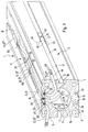
- the linear drive 1 is designed as a so-called rodless working cylinder. It has a tubular housing 2 with a linear longitudinal extension, which in the present case is designed as a profile tube. It consists in particular of aluminum material and can be an extruded drawing profile.
- a longitudinally extending interior 3 This receives an axially displaceable piston 4 which divides the interior 3 into two work spaces. Both working spaces can be pressurized with a fluid pressure medium, so that the piston 4 is displaced axially in the longitudinal direction 5.
- This piston movement can be tapped on the outside of the housing 2 at a driver 6 connected to the piston 4.
- This is motionally coupled to the piston 4 and projects outwards through a longitudinal slot 7 in the housing 2.
- a sealing tape 8 is used to seal the interior 3, that bears against the flanks of the longitudinal slot 7 from the inside and covers it.
- Linear drives of this type are generally referred to as slot cylinders. Further details on their basic design can be found, for example, in DE 41 37 789 C2, to which reference is hereby made.
- the housing 2 of the exemplary embodiment has a rectangular, in particular square, outer cross-sectional profile. It thus has four outer surfaces 9 extending in the longitudinal direction. One of these outer surfaces is longitudinally divided by the longitudinal slot 7 in the middle. In the other of the outer surfaces 9, a linear anchoring groove 10 extending in the longitudinal direction over the entire length of the housing is introduced. These anchoring grooves 10 advantageously also run centrally, so that they divide the assigned outer surface 9 into two longitudinal strips of the same width. In principle, it would of course also be possible to assign more than one anchoring groove 10 to one or more of the outer surfaces 9 or to provide no anchoring groove at all. However, the arrangement distributed over the outer circumference has the advantage a more universal usability.
- the anchoring grooves 10 serve primarily for fastening sensors 14 which, in the exemplary embodiment, serve to detect certain axial positions of the piston 4.
- the construction of these sensors 14 is in principle arbitrary, for example inductive sensors, magnetoresistive sensors or magnetostrictive sensors. In the exemplary embodiment, they are formed by so-called reed switches, which are actuated by a magnetic field entering their area of influence. In the present case, this magnetic field is supplied by a permanent magnetic magnet device 15 which is attached to the piston 4. As soon as the piston 4 with the magnetic device 15 moves radially inward past a sensor 14, the latter is actuated without contact, so that it emits one or more sensor signals.
- sensor signals are transmitted via a sensor cable 13 arranged on the respective sensor 14 to a control device, not shown, for example a programmable logic controller (PLC).
- PLC programmable logic controller
- This control device may, for example, be able to actuate a valve device as a function of the sensor signals received, which in turn controls the supply and discharge of pressure medium with respect to the linear drive 1, so that in this way the operating behavior of the Linear drive 1 is possible.
- the anchoring grooves 10 can also be used to fix additional components to the housing 2.
- another linear drive could be attached to create a multi-axis drive unit.
- the attachment is preferably carried out using so-called slot nuts 16, which, like the sensors 14, can be fixed in the anchoring groove 10.
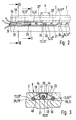
- the anchoring grooves 10 each have a constriction-defining groove neck 17, which expediently runs at least approximately in the associated outer surface 9 and forms the slot-like longitudinal opening of the anchoring groove 10, via which the anchoring groove is open over its entire length to the outer surface 9.
- an anchoring section 18 which is wider than the groove neck 17.
- the anchoring groove 10 widens on both sides in the transverse direction, so that the Groove neck 17 comes to lie centrally over the anchoring section 18.
- the groove neck 17 can be formed directly from the narrowest area of the groove cross section.
- the groove neck 17 has a certain small depth, for example in the range of 2 mm, which is followed by the anchoring section 18.
- This is laterally delimited by two groove flanks 19, each of which, seen in cross section, has an oblique course and, starting from the groove neck 17, moves away from one another in the depth direction. At their end, they transition into the groove base 21 with a transition region 20, which in the present case runs parallel to the assigned outer surface 9.
- the anchoring section 18 thus has the cross-sectional shape similar to an isosceles trapezoid.
- the sensors 14 have an essentially block-like shape. They have a housing 22 with a stepped rectangular cross section. A housing section forms a fastening section 23, its height corresponds approximately to the height of the anchoring section 18, and its width is somewhat larger than the width of the groove neck 17. A respective sensor 14 is received with its fastening section 23 in the anchoring section 18 of the associated anchoring groove 10. A slightly narrower strip-shaped centering section 24 adjoins the fastening section 23 toward the outer surface 9 whose width corresponds approximately to the width of the groove neck 17 into which it projects. In this way, a sensor 14 inserted into the anchoring groove 10 is both fixed in the transverse direction and secured against being lifted out through the groove neck 17. The wider neck portion 23 engages behind the groove neck 17.
- the centering section 24 can protrude outside over the outer surface 9.
- the centering section 24 closes off within the anchoring groove 10, it expediently running flush with the outer surface 9.
- a sensor 14 is installed in an anchoring groove 10 in such a way that the sensor 14 in question is inserted into the anchoring groove 10 which is open at the end. If the desired longitudinal position along the housing 2 is reached, the sensor 14 is detachably fixed to the housing. In the exemplary embodiment, this is done with the aid of at least one clamping screw 25 which runs in a thread of the housing 22 and passes through it in the groove depth direction. If the clamping screw 25 is screwed against the groove base 21, the fastening section 23 becomes upward against the wall sections of the anchoring section flanking the groove neck 17 on both sides 18 pressed and thus clamped.
- the cross-sectional design of the fastening section 23 of a respective sensor 14 is matched to the cross-sectional design of the anchoring section 18 of the anchoring groove 10 in such a way that two cable lead-through channels are provided between the fastening section 23 of the sensor arranged in the anchoring groove 10 and the wall 26 of the anchoring section 18 27, 27 'are present.
- the cable feed-through channels 27, 27 ′ assigned to a respective sensor 14 make it possible to pass the sensor cables 13 of the other sensors 14 while simultaneously fixing a plurality of sensors 14 in one and the same anchoring groove 10 and in this way lead past the relevant sensor 14 within the anchoring groove 10.
- the arrangement is such that there are two such cable feed-through channels 27, 27 'next to each sensor 14, which flank the sensor 14 on opposite longitudinal sides. They are located in the mentioned transition areas 20.
- the laying of the sensor cable 13 is facilitated by the fact that in the mentioned transition areas 20 additional longitudinal recesses 28 are formed in the anchoring section 18, which enlarge the groove cross section in the manner of fillets.
- the longitudinal depressions 28, 28 ' are formed like a channel, with a concave rounded shape, which can be an arcuate curvature which, for example, is adapted to the diameter of the sensor cable 13.
- the linear drive 1 is here equipped in the upwardly facing anchoring groove 10 with three axially successively arranged sensors 14 of the type described.
- the cable exit points 29, at which the sensor cables 13 emerge from the assigned sensor 14, are located on an end face 33 of the sensor housing 22.
- the sensor cables 13 can be hard-wired to the sensor 14, as shown.
- the cable exit points 29 are located within the associated anchoring groove 10, so that the sensor cable 13 in question leads directly into the anchoring groove 10 in question.
- the three sensors 14 are arranged so that their cable exit points 29 point in the same axial direction to the same front end region 34 of the housing 2 of the linear drive 1.
- the sensor cable 13, 13 'of the sensor 14, 14' closest to the front end region 34 runs in a straight line in the center of the anchoring groove 10 and only emerges at the open end of the anchoring groove 10 at the front end region 34.
- the sensor cable 13' is completely immersed in the anchoring groove 10 and in particular in the anchoring section 18.
- the sensor cable 13 ′′ of the subsequent middle sensor 14 ′′ initially runs a bit in the groove section 36 lying between the first and the second sensor 14 ′, 14 ′′. It then swivels to the side and passes through the one cable duct 27 ′ next to it the first sensor 14 '. Subsequently, it continues in the adjoining section of the assigned longitudinal recess 28 until it also reaches the exit point 35.
- the sensor cable 13 '' 'of the third sensor 14, 14' ''' runs through a cable duct 27 of the middle sensor 14 '' and then through a cable duct 27 of the first sensor 14 'on the same side to the exit point 35 is inserted into the cable duct 27 of the middle sensor 14 '', it expediently runs straight to the exit point 35 in the associated longitudinal recess 28.
- An advantage of the arrangement is that the longitudinal position of a respective sensor 14 can be varied as desired without colliding with the sensor cables 13 running past or damaging them. There is therefore no restriction on the adjustability of the individual sensors 14.
- the cover strip 37 closes the longitudinal section 38 of the anchoring groove 10 lying between the first sensor 14 'and the end region 34. It is profiled in a U-shaped manner according to the example and has a cover strip 39 from which two retaining legs 40 extend at the edge. Outside is in the transition area between the cover strip 39 and a respective holding leg 40 a continuous recess 44 in the longitudinal direction.
- the holding legs 40 are tapered towards their end, whereby they can be bent. Overall, they are resilient in the transverse direction with respect to the cover strip 39.
- the cover strip 37 is pressed into the anchoring groove 10 with its U opening ahead until the longitudinal recesses 44 snap into the groove neck.
- the cover strip 39 expediently runs flush with the outer surface 9.
- One of the sensor cables 13, 13 'can run in the interior of the cover strip 39, which is delimited by the U-shape.
- the two other sensor cables 13 ′′, 13 ′′ ′′ run on both sides of the cover strip 37 next to a respective holding leg 40.
- the cover strip 37 is advantageously made of plastic material and can be cut to any desired length. In this way, all of the longitudinal sections of the anchoring groove 10 can be closed, including intermediate regions between sensors 14 arranged in succession at a distance.
- the cross-sectional contour of the anchoring groove 10 has the further advantage that it is able to withstand large forces Record so that it is also suitable for anchoring sliding blocks 16.
- One and the same type of anchoring groove 10 can therefore be used either optionally or simultaneously for anchoring sensors 14 or slot nuts 16. This results in a considerable gain in construction volume.
- the sliding blocks 16 can be placed with a holding section 45 in the anchoring section 18 of the anchoring groove 10.
- the cross-sectional contour of the holding section 45 corresponds to that of the anchoring section 18, but apart from the cross-sectional areas defined by the longitudinal recesses 28.
- a respective holding section 45 also forms cable feed-through channels 46 with the currently assigned length section of the longitudinal depressions 28. They allow the passage of sensor cables 13, which are arranged in the same anchoring groove 10 as the relevant slot nut 16.
- a neck section 47 adjoining the holding section 45 projects into the groove neck 17 and can still be inside the outer surface 9 or finish flush with this.
- the sliding block 16 has fastening means 48 known per se, for example a thread, which enable the fastening of additional components.
- the sensor cables of the exemplary embodiment are of multi-core design and include, for example, two or more wires 48 which are surrounded by a common sheath 49.
Landscapes
- Engineering & Computer Science (AREA)
- Mechanical Engineering (AREA)
- Power Engineering (AREA)
- Physics & Mathematics (AREA)
- Fluid Mechanics (AREA)
- General Engineering & Computer Science (AREA)
- Control Of Electric Motors In General (AREA)
- Testing Or Calibration Of Command Recording Devices (AREA)
- Actuator (AREA)
Applications Claiming Priority (2)
| Application Number | Priority Date | Filing Date | Title |
|---|---|---|---|
| DE29501140U DE29501140U1 (de) | 1995-01-25 | 1995-01-25 | Linearantrieb mit Sensorausstattung |
| DE29501140U | 1995-01-25 |
Publications (2)
| Publication Number | Publication Date |
|---|---|
| EP0724268A1 true EP0724268A1 (fr) | 1996-07-31 |
| EP0724268B1 EP0724268B1 (fr) | 1998-07-08 |
Family
ID=8002939
Family Applications (1)
| Application Number | Title | Priority Date | Filing Date |
|---|---|---|---|
| EP95116646A Expired - Lifetime EP0724268B1 (fr) | 1995-01-25 | 1995-10-23 | Moteur électrique linéaire avec méthode d'analyse sensorielle |
Country Status (2)
| Country | Link |
|---|---|
| EP (1) | EP0724268B1 (fr) |
| DE (2) | DE29501140U1 (fr) |
Cited By (4)
| Publication number | Priority date | Publication date | Assignee | Title |
|---|---|---|---|---|
| DE29717081U1 (de) * | 1997-09-24 | 1997-12-04 | Pepperl & Fuchs GmbH, 68307 Mannheim | Mehrfachsensor, insbesondere zur Endlagen- und Grenzwerterfassung |
| DE19648679A1 (de) * | 1996-11-25 | 1998-06-04 | Bosch Gmbh Robert | Zylinderschalter |
| DE19712829A1 (de) * | 1997-03-26 | 1998-10-01 | Sick Ag | Vorrichtung zur Erkennung der Position eines beweglichen Gegenstandes |
| DE19716736A1 (de) * | 1997-04-14 | 1998-10-15 | Mannesmann Ag | Einrichtung zur Sensorbefestigung |
Families Citing this family (4)
| Publication number | Priority date | Publication date | Assignee | Title |
|---|---|---|---|---|
| DE29904367U1 (de) | 1999-03-10 | 1999-05-27 | Festo AG & Co, 73734 Esslingen | Vorrichtung zur Befestigung eines Sensors |
| DE102006013305B3 (de) * | 2006-03-21 | 2007-07-05 | Minimax Gmbh & Co. Kg | Feuerlöscheinrichtung zum Löschen definierter Objekte |
| DE102007008338B4 (de) * | 2007-02-20 | 2009-12-17 | Festo Ag & Co. Kg | Positionssensoreinrichtung und damit ausgestatteter Aktor |
| DE102008046827A1 (de) * | 2008-09-11 | 2010-03-25 | Festo Ag & Co. Kg | Linearantriebsvorrichtung |
Citations (6)
| Publication number | Priority date | Publication date | Assignee | Title |
|---|---|---|---|---|
| DE2516495A1 (de) * | 1975-04-15 | 1976-10-28 | Fritz Dipl Ing Deyle | Anschlussleiste mit verdeckt angeordneten stromschienen |
| DE3923063A1 (de) | 1989-04-08 | 1990-10-11 | Festo Kg | Steuereinrichtung |
| DE4127205A1 (de) * | 1991-08-14 | 1993-02-18 | Mannesmann Ag | Linearantrieb mit einem antriebsgehaeuse und einem sensor |
| DE4127204A1 (de) * | 1991-08-14 | 1993-02-18 | Mannesmann Ag | Sensorbefestigung mit verbindungsmittel fuer ein langgestrecktes gehaeuse |
| DE4137789A1 (de) | 1991-11-16 | 1993-05-19 | Festo Kg | Linearantrieb |
| DE9414869U1 (de) | 1994-09-13 | 1994-12-08 | Festo Kg, 73734 Esslingen | Vorrichtung zur lösbaren Verankerung eines Sensors |
Family Cites Families (4)
| Publication number | Priority date | Publication date | Assignee | Title |
|---|---|---|---|---|
| DE4030372C1 (en) * | 1990-09-26 | 1991-11-21 | Murrelektronik Gmbh, 7155 Oppenweiler, De | Electrical component plug-in housing - has two projections on locating foot separated by variable distance to fit gap |
| DE4141162A1 (de) * | 1991-12-13 | 1993-06-17 | Turck Werner Kg | Befestigungsklemme zur anbringung von naeherungssensoren an druckmittelzylindern |
| DE9304474U1 (de) * | 1993-03-24 | 1993-09-16 | Mengemann, Dieter, 67433 Neustadt | T-Nuten Abdeckprofil |
| DE4312062A1 (de) * | 1993-04-13 | 1994-10-20 | Balluff Gebhard Feinmech | Sensorsystem |
-
1995
- 1995-01-25 DE DE29501140U patent/DE29501140U1/de not_active Expired - Lifetime
- 1995-10-23 EP EP95116646A patent/EP0724268B1/fr not_active Expired - Lifetime
- 1995-10-23 DE DE59502757T patent/DE59502757D1/de not_active Expired - Lifetime
Patent Citations (6)
| Publication number | Priority date | Publication date | Assignee | Title |
|---|---|---|---|---|
| DE2516495A1 (de) * | 1975-04-15 | 1976-10-28 | Fritz Dipl Ing Deyle | Anschlussleiste mit verdeckt angeordneten stromschienen |
| DE3923063A1 (de) | 1989-04-08 | 1990-10-11 | Festo Kg | Steuereinrichtung |
| DE4127205A1 (de) * | 1991-08-14 | 1993-02-18 | Mannesmann Ag | Linearantrieb mit einem antriebsgehaeuse und einem sensor |
| DE4127204A1 (de) * | 1991-08-14 | 1993-02-18 | Mannesmann Ag | Sensorbefestigung mit verbindungsmittel fuer ein langgestrecktes gehaeuse |
| DE4137789A1 (de) | 1991-11-16 | 1993-05-19 | Festo Kg | Linearantrieb |
| DE9414869U1 (de) | 1994-09-13 | 1994-12-08 | Festo Kg, 73734 Esslingen | Vorrichtung zur lösbaren Verankerung eines Sensors |
Cited By (7)
| Publication number | Priority date | Publication date | Assignee | Title |
|---|---|---|---|---|
| DE19648679A1 (de) * | 1996-11-25 | 1998-06-04 | Bosch Gmbh Robert | Zylinderschalter |
| DE19648679C2 (de) * | 1996-11-25 | 1999-10-14 | Bosch Gmbh Robert | Zylinderschalter |
| DE19712829A1 (de) * | 1997-03-26 | 1998-10-01 | Sick Ag | Vorrichtung zur Erkennung der Position eines beweglichen Gegenstandes |
| DE19712829B4 (de) * | 1997-03-26 | 2005-02-17 | Sick Ag | Vorrichtung zur Erkennung der Position eines beweglichen Gegenstandes |
| DE19716736A1 (de) * | 1997-04-14 | 1998-10-15 | Mannesmann Ag | Einrichtung zur Sensorbefestigung |
| DE19716736C2 (de) * | 1997-04-14 | 2002-02-07 | Rexroth Mecman Gmbh | Einrichtung zur Sensorbefestigung |
| DE29717081U1 (de) * | 1997-09-24 | 1997-12-04 | Pepperl & Fuchs GmbH, 68307 Mannheim | Mehrfachsensor, insbesondere zur Endlagen- und Grenzwerterfassung |
Also Published As
| Publication number | Publication date |
|---|---|
| DE59502757D1 (de) | 1998-08-13 |
| EP0724268B1 (fr) | 1998-07-08 |
| DE29501140U1 (de) | 1995-04-13 |
Similar Documents
| Publication | Publication Date | Title |
|---|---|---|
| DE8424035U1 (de) | Kolbenstangenloser zylinder | |
| EP0313767B1 (fr) | Dispositif de serrage | |
| EP0177693A2 (fr) | Potentiomètre | |
| DE8408571U1 (de) | Pneumatikschlauch | |
| DE19758916B4 (de) | Linearführungseinheit | |
| EP0724268B1 (fr) | Moteur électrique linéaire avec méthode d'analyse sensorielle | |
| DE3411823C3 (fr) | ||
| EP1182359B1 (fr) | Actionneur linéaire sans tige et son carter | |
| DE10150709A1 (de) | Markise | |
| DE9104532U1 (de) | Kniehebelspannvorrichtung für den Karosseriebau | |
| DE102008015447A1 (de) | Sensor und damit ausgestattetes Arbeitsgerät | |
| DE4431148C2 (de) | Elektro-Installationsdose und Werkzeug zum Einsetzen eines Einsatzes in diese | |
| DE3524414C2 (de) | Linearantrieb | |
| EP1580476A1 (fr) | Raccord pour conduits de fluide | |
| EP0212421A2 (fr) | Cylindre actionnable par fluide sous pression | |
| EP0645215B1 (fr) | Plaque de fixation | |
| DE202005008668U1 (de) | Leitungsführungseinrichtung für biegbare elektrische oder fluidische Leitungen | |
| EP0997655A1 (fr) | Guide linéaire | |
| DE3815992C2 (fr) | ||
| DE3601741A1 (de) | Aus biegbarem kunststoffmaterial bestehende schlauchanordnung | |
| DE102004018818A1 (de) | Wegmess-Vorrichtung | |
| DE19626205C2 (de) | Kabelanschlußkasten | |
| DE102014110508A1 (de) | Führungsrinnensystem für eine Energiekette und Maschine mit in Führungsrinnensystem geführter Energiekette | |
| DE8632990U1 (de) | Berührungsloser Sensor | |
| DE9304053U1 (de) | Verbindungseinrichtung für Profilteile |
Legal Events
| Date | Code | Title | Description |
|---|---|---|---|
| PUAI | Public reference made under article 153(3) epc to a published international application that has entered the european phase |
Free format text: ORIGINAL CODE: 0009012 |
|
| AK | Designated contracting states |
Kind code of ref document: A1 Designated state(s): DE FR IT NL SE |
|
| 17P | Request for examination filed |
Effective date: 19960613 |
|
| RAP1 | Party data changed (applicant data changed or rights of an application transferred) |
Owner name: FESTO AG & CO |
|
| GRAG | Despatch of communication of intention to grant |
Free format text: ORIGINAL CODE: EPIDOS AGRA |
|
| GRAG | Despatch of communication of intention to grant |
Free format text: ORIGINAL CODE: EPIDOS AGRA |
|
| GRAH | Despatch of communication of intention to grant a patent |
Free format text: ORIGINAL CODE: EPIDOS IGRA |
|
| 17Q | First examination report despatched |
Effective date: 19971210 |
|
| GRAH | Despatch of communication of intention to grant a patent |
Free format text: ORIGINAL CODE: EPIDOS IGRA |
|
| GRAA | (expected) grant |
Free format text: ORIGINAL CODE: 0009210 |
|
| AK | Designated contracting states |
Kind code of ref document: B1 Designated state(s): DE FR IT NL SE |
|
| ITF | It: translation for a ep patent filed | ||
| REF | Corresponds to: |
Ref document number: 59502757 Country of ref document: DE Date of ref document: 19980813 |
|
| ET | Fr: translation filed | ||
| PLBE | No opposition filed within time limit |
Free format text: ORIGINAL CODE: 0009261 |
|
| STAA | Information on the status of an ep patent application or granted ep patent |
Free format text: STATUS: NO OPPOSITION FILED WITHIN TIME LIMIT |
|
| 26N | No opposition filed | ||
| PGFP | Annual fee paid to national office [announced via postgrant information from national office to epo] |
Ref country code: NL Payment date: 20081017 Year of fee payment: 14 |
|
| PGFP | Annual fee paid to national office [announced via postgrant information from national office to epo] |
Ref country code: SE Payment date: 20081017 Year of fee payment: 14 |
|
| PGFP | Annual fee paid to national office [announced via postgrant information from national office to epo] |
Ref country code: FR Payment date: 20081021 Year of fee payment: 14 |
|
| REG | Reference to a national code |
Ref country code: NL Ref legal event code: V1 Effective date: 20100501 |
|
| EUG | Se: european patent has lapsed | ||
| REG | Reference to a national code |
Ref country code: FR Ref legal event code: ST Effective date: 20100630 |
|
| PG25 | Lapsed in a contracting state [announced via postgrant information from national office to epo] |
Ref country code: NL Free format text: LAPSE BECAUSE OF NON-PAYMENT OF DUE FEES Effective date: 20100501 Ref country code: FR Free format text: LAPSE BECAUSE OF NON-PAYMENT OF DUE FEES Effective date: 20091102 |
|
| PG25 | Lapsed in a contracting state [announced via postgrant information from national office to epo] |
Ref country code: SE Free format text: LAPSE BECAUSE OF NON-PAYMENT OF DUE FEES Effective date: 20091024 |
|
| PGFP | Annual fee paid to national office [announced via postgrant information from national office to epo] |
Ref country code: DE Payment date: 20120811 Year of fee payment: 18 |
|
| PGFP | Annual fee paid to national office [announced via postgrant information from national office to epo] |
Ref country code: IT Payment date: 20121024 Year of fee payment: 18 |
|
| REG | Reference to a national code |
Ref country code: DE Ref legal event code: R119 Ref document number: 59502757 Country of ref document: DE Effective date: 20140501 |
|
| PG25 | Lapsed in a contracting state [announced via postgrant information from national office to epo] |
Ref country code: DE Free format text: LAPSE BECAUSE OF NON-PAYMENT OF DUE FEES Effective date: 20140501 Ref country code: IT Free format text: LAPSE BECAUSE OF NON-PAYMENT OF DUE FEES Effective date: 20131023 |