EP0724332A1 - Schaltvorrichtung für Hochspannungsschaltung mit Impulstransformator - Google Patents
Schaltvorrichtung für Hochspannungsschaltung mit Impulstransformator Download PDFInfo
- Publication number
- EP0724332A1 EP0724332A1 EP96400166A EP96400166A EP0724332A1 EP 0724332 A1 EP0724332 A1 EP 0724332A1 EP 96400166 A EP96400166 A EP 96400166A EP 96400166 A EP96400166 A EP 96400166A EP 0724332 A1 EP0724332 A1 EP 0724332A1
- Authority
- EP
- European Patent Office
- Prior art keywords
- transformers
- transformer
- switches
- voltage circuit
- high voltage
- Prior art date
- Legal status (The legal status is an assumption and is not a legal conclusion. Google has not performed a legal analysis and makes no representation as to the accuracy of the status listed.)
- Granted
Links
- 238000004804 winding Methods 0.000 claims abstract description 25
- 239000007787 solid Substances 0.000 claims abstract description 5
- 239000002184 metal Substances 0.000 claims abstract description 3
- 229910052751 metal Inorganic materials 0.000 claims abstract description 3
- 238000000465 moulding Methods 0.000 claims abstract description 3
- 238000002955 isolation Methods 0.000 claims description 13
- 238000010292 electrical insulation Methods 0.000 claims description 2
- 230000001131 transforming effect Effects 0.000 claims 2
- 238000009413 insulation Methods 0.000 description 14
- 238000004519 manufacturing process Methods 0.000 description 8
- 230000005684 electric field Effects 0.000 description 3
- 230000005669 field effect Effects 0.000 description 3
- 230000032683 aging Effects 0.000 description 2
- 230000000712 assembly Effects 0.000 description 2
- 238000000429 assembly Methods 0.000 description 2
- 239000012212 insulator Substances 0.000 description 2
- 229910044991 metal oxide Inorganic materials 0.000 description 2
- 150000004706 metal oxides Chemical class 0.000 description 2
- 239000004065 semiconductor Substances 0.000 description 2
- 230000009466 transformation Effects 0.000 description 2
- RYGMFSIKBFXOCR-UHFFFAOYSA-N Copper Chemical compound [Cu] RYGMFSIKBFXOCR-UHFFFAOYSA-N 0.000 description 1
- 239000004809 Teflon Substances 0.000 description 1
- 229920006362 Teflon® Polymers 0.000 description 1
- 230000005540 biological transmission Effects 0.000 description 1
- 230000015556 catabolic process Effects 0.000 description 1
- 229910010293 ceramic material Inorganic materials 0.000 description 1
- 239000004020 conductor Substances 0.000 description 1
- 238000010276 construction Methods 0.000 description 1
- 229910052802 copper Inorganic materials 0.000 description 1
- 239000010949 copper Substances 0.000 description 1
- 230000007423 decrease Effects 0.000 description 1
- 239000011810 insulating material Substances 0.000 description 1
- 239000000696 magnetic material Substances 0.000 description 1
- 230000035699 permeability Effects 0.000 description 1
- 230000000135 prohibitive effect Effects 0.000 description 1
- 238000005245 sintering Methods 0.000 description 1
- 239000011343 solid material Substances 0.000 description 1
- 229910000859 α-Fe Inorganic materials 0.000 description 1
Images


Classifications
-
- H—ELECTRICITY
- H01—ELECTRIC ELEMENTS
- H01F—MAGNETS; INDUCTANCES; TRANSFORMERS; SELECTION OF MATERIALS FOR THEIR MAGNETIC PROPERTIES
- H01F19/00—Fixed transformers or mutual inductances of the signal type
- H01F19/04—Transformers or mutual inductances suitable for handling frequencies considerably beyond the audio range
- H01F19/08—Transformers having magnetic bias, e.g. for handling pulses
-
- H—ELECTRICITY
- H03—ELECTRONIC CIRCUITRY
- H03K—PULSE TECHNIQUE
- H03K17/00—Electronic switching or gating, i.e. not by contact-making and –breaking
- H03K17/10—Modifications for increasing the maximum permissible switched voltage
- H03K17/102—Modifications for increasing the maximum permissible switched voltage in field-effect transistor switches
-
- H—ELECTRICITY
- H03—ELECTRONIC CIRCUITRY
- H03K—PULSE TECHNIQUE
- H03K17/00—Electronic switching or gating, i.e. not by contact-making and –breaking
- H03K17/10—Modifications for increasing the maximum permissible switched voltage
- H03K17/107—Modifications for increasing the maximum permissible switched voltage in composite switches
-
- H—ELECTRICITY
- H03—ELECTRONIC CIRCUITRY
- H03K—PULSE TECHNIQUE
- H03K17/00—Electronic switching or gating, i.e. not by contact-making and –breaking
- H03K17/51—Electronic switching or gating, i.e. not by contact-making and –breaking characterised by the components used
- H03K17/56—Electronic switching or gating, i.e. not by contact-making and –breaking characterised by the components used by the use, as active elements, of semiconductor devices
- H03K17/687—Electronic switching or gating, i.e. not by contact-making and –breaking characterised by the components used by the use, as active elements, of semiconductor devices the devices being field-effect transistors
- H03K17/689—Electronic switching or gating, i.e. not by contact-making and –breaking characterised by the components used by the use, as active elements, of semiconductor devices the devices being field-effect transistors with galvanic isolation between the control circuit and the output circuit
- H03K17/691—Electronic switching or gating, i.e. not by contact-making and –breaking characterised by the components used by the use, as active elements, of semiconductor devices the devices being field-effect transistors with galvanic isolation between the control circuit and the output circuit using transformer coupling
-
- H—ELECTRICITY
- H01—ELECTRIC ELEMENTS
- H01F—MAGNETS; INDUCTANCES; TRANSFORMERS; SELECTION OF MATERIALS FOR THEIR MAGNETIC PROPERTIES
- H01F19/00—Fixed transformers or mutual inductances of the signal type
- H01F19/04—Transformers or mutual inductances suitable for handling frequencies considerably beyond the audio range
- H01F19/08—Transformers having magnetic bias, e.g. for handling pulses
- H01F2019/085—Transformer for galvanic isolation
Definitions
- the invention relates to a high frequency switching device for a high voltage circuit with pulse transformers.
- Such a switching device allows rapid opening and closing of a high voltage circuit from control pulses of a low voltage circuit.
- high voltage is meant a voltage of a few tens to a few hundred kilovolts and by high frequency, a frequency ranging from a few kilohertz to a few megahertz.
- the invention finds applications in fields such as power supplies for pulse lasers, fast pulse generators, high voltage power supplies and converters.
- a large number of stages of insulated gate transistors are generally used. For example, for the production of switches or switching devices capable of withstanding voltage from 20 to 100 kilovolts, 50 to 100 stages of transistors connected in series are necessary. The switching on and off of the transistors is done in response to control pulses in a low voltage circuit. These low voltage commands are transmitted to the transistors or to the switches via a device capable of ensuring galvanic isolation between the low voltage circuit and the high voltage circuit in which the switches. The transmission of control pulses or control commands can take place, for example, by pulse transformers.
- Switching devices with pulse transformers are known for example in documents (1) and (2) referenced at the end of this description.
- a common pulse transformer for all of the switches.
- Such a transformer has a plurality of secondary stages connected respectively to each of the switches.
- the pulse transformer provides galvanic isolation between the primary circuit, that is to say the low voltage circuit on which the control pulses are supplied, and each secondary circuit, connected to high voltage, and comprising a switch.
- the transformer also provides insulation between the different secondary stages.
- Document (2) illustrates an alternative embodiment of a switching device which uses not a single transformer with several secondary stages but uses a plurality of transformers whose primary stages are connected in series in a low voltage circuit.
- Each transformer has an O-ring core and each O-ring is traversed by an insulated electrical cable which respectively forms the primary of each transformer and which is mounted in the low voltage circuit.
- This cable has an insulation with respect to the high voltage
- each transformer also includes a secondary circuit formed by a winding around the toroid and connected respectively to a switch.
- the galvanic isolation between the common primary stage and the secondary stages of the transformers as well as the galvanic isolation between the various secondary stages of the transformers is ensured by the insulation of the cable of the primary circuit. This insulation must therefore be able to withstand high voltage and at high frequency.
- the electric field between different consecutive insulating materials increases as the inverse of relative permeability.
- the field in an air bubble trapped in a solid insulator is more important than the electric field in the solid material itself.
- a plasma appears in the air bubble, this plasma being liable to degrade the insulation.
- This physical phenomenon which essentially results in the appearance of partial discharges in solid insulators, limits their performance and their lifespan.
- the aging due to partial discharges increases substantially linearly with the operating frequency.
- This aging is therefore particularly rapid for high frequency devices.
- a switching device which comprises a plurality of toroidal pulse transformers crossed by a single cable which forms their primary stage, sufficient insulation of this cable supposes an outside diameter of the latter of the order 10mm for a voltage withstand of 20kV.
- a device produced in accordance with document (2) thus does not make it possible to control a very large number of transistors for switching a high voltage to a high frequency.
- cables equipped with a thick insulation sheath that is to say primary cables whose diameter is large.
- the internal diameter of the core of the transformer cores must also be dimensioned accordingly.
- the toroids sold on the market respect an almost constant relationship between their diameter and their section.
- a torus with a diameter of a few cm has a section of the order of cm 2 for example.
- An object of the present invention is therefore to propose a switching device for a high voltage circuit with pulse transformers which is both efficient from the point of view of the speed of switching, reliability over time and which or of a reasonable compactness for the production of switches in high and very high voltage, fast and with a high recurrence frequency.
- Another object of the invention is to provide a device whose production is not only low cost but also compatible with the requirements of industrial manufacturing.
- the invention relates more particularly to a switching device of a high voltage circuit with pulse transformer, comprising a plurality of switches with switches connected in series in the high voltage circuit, means of transformation pulse connected on the one hand to a low voltage circuit and on the other hand to said switches and making it possible to supply switching pulses for the switches in response to control pulses in a low voltage circuit.
- the pulse transformation means comprise at least a first transformer with a primary stage for receiving the control pulses and a secondary stage, each secondary stage of each first transformer is connected to primary stages respectively of a plurality of second transformers for providing switching pulses to said plurality of switches connected respectively to the plurality of second transformers, and each first transformer has greater galvanic isolation than that of the second transformers.
- the low and high voltage circuits are mutually isolated by the first (s) and the second transformers.
- each first transformer which has significant galvanic isolation The plurality of second transformers which is associated with the transistors, not having to withstand a very large potential difference, can be small and above all present a core of small volume. So with just one larger volume transformer, and a plurality of smaller volume transformers, it is possible to control a plurality of transistors. Of course, it is possible, when the number of transistors to be controlled is very large, to use several first transformers, each being associated with a plurality of second transformers.
- the transformers are toroidal transformers
- the volume occupied by the transformers is much lower than the volume occupied by the transformers of the known switching devices, for example those of the devices of the documents (1) and (2). previously described.
- the device of the invention comprises a plurality of first transformers, these can have their primary stages connected in series in the low voltage circuit.
- a single cable with high electrical insulation can form the primary stage by crossing all the cores of the first transformers.
- the core of the first transformer can be electrically connected to the secondary stage of the first transformer and the cores of the second transformers are electrically connected to the high voltage circuit.
- the galvanic isolation between the low voltage circuit and the high voltage circuit is essentially provided by the isolation of primary stages of the first transformer (s).
- the low voltage circuit may for example comprise a rigid metal rod which passes through the toroidal core or cores of the first transformers, respectively forming their primary stage. This rod is then isolated from the cores, for example by a solid molding.
- the secondary stage of the first transformer may include a single winding connected to the primary stages of the second transformers connected in series, it may also be a cable passing through the toroidal cores of the second transformers.
- One solution consists, for example in using second transformers with a single secondary stage, that is to say with a single winding connected respectively to a switch. It is also possible to use second transformers with a plurality of windings connected respectively to a plurality of switches.
- the switches are built essentially around transistors of the field effect type. These transistors can for example be MOS transistors, that is to say with a metal oxide semiconductor structure, IGBT transistors which are bipolar insulated gate transistors as well as MCT transistors.
- MOS transistors that is to say with a metal oxide semiconductor structure
- IGBT transistors which are bipolar insulated gate transistors as well as MCT transistors.
- the gates of the transistors or the control electrodes of the latter are connected to the secondary stage of the transformers, for example by an intermediate control circuit.
- a switching device comprises a plurality of switches 10 with switches 12 connected in series in a branch 14 of a high voltage circuit.
- control pulses are formed in a low voltage circuit 16, partially shown. These pulses are transmitted to the switches 10 via a series of first transformers 118, 218, 318, 418 and a series of second transformers 120, 220 of which only a few are shown entirely in the figure.
- Sets referenced 100, 200, 300, 400 respectively designate the second transformers associated with the first transformers 118, 218, 318 and 418. For reasons of clarity, the assemblies 300 and 400 are not detailed in the figure.
- the primary stages 122, 222, 322, 422 of the first transformers are formed by a branch of the low voltage circuit 16 which goes from a terminal 24 to a terminal 26.
- the secondary stages 128, 228, 328, 428 of the first transformers are respectively connected to primary stages of the second transformers. For reasons of clarity of the figure, this only represents the primary stages 130 and 230 connected to the secondary stages 128 and 228 of the first transformers.
- the primary stages 130 and 230 of the second transformers are respectively connected in series in circuits 132, 232 which connect them to the first transformers. Circuits 332, 432 likewise connect stages 328 and 428 to second transformers of assemblies 300 and 400, not shown.
- the number of second transformers, the number of stages in series, as well as the number of first transformers can be adapted for each particular embodiment according to the voltage to be switched.
- the secondary stages of the second transformers are respectively connected to the switches 10. These switches include a control circuit 36 associated with switches 12.
- the second transformers may include a secondary stage with one or more windings.
- the transformers 120 comprise a secondary stage with a single winding 34
- the transformers 230 comprise a secondary stage with two windings 34 and 34 ', connected respectively to a switch 12 via a circuit 36.
- the galvanic isolation between the low and high voltage circuits is ensured by the primary stages of the transformers.
- the cores 140, 240, 340, 440 of the first transformers and the cores 40, 42 of the second transformers are electrically connected to circuits 132, 232, 332, 432 and to circuit 14 respectively.
- a link 511 which connects a terminal 512 of the circuit 132 to a terminal 513 of the branch 14 of the high voltage circuit.
- This connection is advantageously carried out at "mid-voltage" on the part of the branch 14 whose switches are controlled via the reference transformers 118 and 120.
- the insulation of the primary stage 130 of the second transformers 120 has to bear only a fraction, at most equal to half of the voltage drop across the terminals of the switches associated with the same first transformer. For example, for a voltage drop of 6000 volts between points 514 and 515 of branch 14, the insulation of the primary stage 130 must support at most 3kV.
- An equivalent link 521 also connects the circuit 232 of the primary stages of the second transformers 220 to the branch 14 of the high voltage circuit.
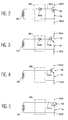
- FIGS. 2 to 5 illustrate different embodiments of the control circuit 36 and of the switches 12.
- the switch 12 is a field effect transistor of the MOSFET (Metal Oxide Semiconductor Field Effect Transistor) type.
- the terminals 520 and 522 which correspond to its drain and its source are mounted in branch 14 of the high voltage circuit.
- Circuit 36 includes a diode 526 which connects a terminal of the secondary winding to the grid 524; the other terminal of the winding being directly connected to the source 522.
- the switch 12 is a bipolar transistor with an insulated gate of the IGBT (Insulated Gate Bipolar Transistor) type.
- the terminals 530 and 532 correspond to the collector and the transmitter and are mounted in the branch 14.
- the circuit 36 includes a diode 526 which connects the grid 534 to a terminal of the winding 34 ; the other terminal of the winding being directly connected to the transmitter.
- the switch 12 is a bipolar transistor whose terminals 540 and 542 correspond to the collector and the emitter and are mounted in the branch 14 of the high voltage circuit.
- the base 544 and the emitter 542 are, moreover, directly connected to the two terminals of the winding 34.
- the switch 12 is a thyristor, the anode 550 and the cathode 552 of which are mounted in the branch 14 of the high voltage circuit.
- the trigger 554 and the cathode 552 are, moreover, directly connected to the two terminals of the winding 34.
- FIGS. 4 and 5 correspond to a current command.
- Figure 6 shows on an enlarged scale the first and second transformers.
- the transformers are toroidal transformers.
- the primary stages of the first transformers 118, 218, 318, 418 are produced from a single cable 22 which connects the terminals 24 and 26 of the bass circuit voltage (not shown) and which passes respectively through the toroidal cores 140, 240, 340 and 440 of the first transformers.
- the cable 22 comprises an electrically conductive core 21, for example made of copper, with a cross section of 4 mm 2 and an insulating sheath 23 in Teflon (registered name) and with a thickness of 10 mm.
- the cable 22 provides both galvanic isolation between the primary and secondary stages of each first transformer and between the secondary stages of the first transformers.
- the insulation and therefore the cross-section of the cables of the windings of the secondary stages can be reduced.
- the cable 22 thus occupies practically the entire internal diameter of the torus.
- the same cable forms the secondary winding, respectively 128, 228, 328, 428, the circuit 132, 232, 332, 432 which connects the winding respectively to the second transformers 120, 220, 320, 420, and the primary stage 130, 230, 330, 430 respectively of the second transformers.
- the second transformers have one (or more) secondary windings 34, 34 'around their core 40. These windings 34, 34' are connected to the switches not shown in FIG. 6.
- the device may include 10 first and 6 second transformers.
- the voltage withstand of the insulation of the primary stage of the first transformers is for example 60kV while that of the primary stage of the second transformers is simply 3kV with the connections at "mid-voltage".
Landscapes
- Engineering & Computer Science (AREA)
- Power Engineering (AREA)
- Multimedia (AREA)
- Electronic Switches (AREA)
Applications Claiming Priority (2)
| Application Number | Priority Date | Filing Date | Title |
|---|---|---|---|
| FR9500894 | 1995-01-26 | ||
| FR9500894A FR2730108A1 (fr) | 1995-01-26 | 1995-01-26 | Dispositif de commutation d'un circuit de haute tension a transformateur d'impulsion |
Publications (2)
| Publication Number | Publication Date |
|---|---|
| EP0724332A1 true EP0724332A1 (de) | 1996-07-31 |
| EP0724332B1 EP0724332B1 (de) | 2003-10-08 |
Family
ID=9475522
Family Applications (1)
| Application Number | Title | Priority Date | Filing Date |
|---|---|---|---|
| EP19960400166 Expired - Lifetime EP0724332B1 (de) | 1995-01-26 | 1996-01-24 | Schaltvorrichtung für Hochspannungsschaltung mit Impulstransformator |
Country Status (3)
| Country | Link |
|---|---|
| EP (1) | EP0724332B1 (de) |
| DE (1) | DE69630252T2 (de) |
| FR (1) | FR2730108A1 (de) |
Cited By (5)
| Publication number | Priority date | Publication date | Assignee | Title |
|---|---|---|---|---|
| GB2341288A (en) * | 1998-06-23 | 2000-03-08 | Eev Ltd | High voltage switching arrangement for driving RF sources |
| GB2356753A (en) * | 1999-11-29 | 2001-05-30 | Eev Ltd | A transmission line triggering arrangement for switching modules |
| EP1254516A4 (de) * | 2000-01-10 | 2008-04-09 | Diversified Technologies Inc | Hochleistungsmodulator |
| EP1923855A1 (de) * | 2006-11-17 | 2008-05-21 | Samsung SDI Co., Ltd. | Plasmaanzeigetafel mit verbesserter Stromversorgungseinheit |
| FR3036013A1 (fr) * | 2015-05-07 | 2016-11-11 | Ge Energy Power Conversion Technology Ltd | Circuit d'attaque de grille pour reduire le couplage parasite |
Citations (2)
| Publication number | Priority date | Publication date | Assignee | Title |
|---|---|---|---|---|
| GB2183952A (en) * | 1985-12-06 | 1987-06-10 | Ferranti Plc | Pulse circuit for switching a grid electrode of an electron beam generator |
| DE3912704A1 (de) * | 1989-04-18 | 1990-10-25 | Siemens Ag | Schaltung zur erzeugung von kurzen leistungsimpulsen |
-
1995
- 1995-01-26 FR FR9500894A patent/FR2730108A1/fr active Granted
-
1996
- 1996-01-24 EP EP19960400166 patent/EP0724332B1/de not_active Expired - Lifetime
- 1996-01-24 DE DE1996630252 patent/DE69630252T2/de not_active Expired - Lifetime
Patent Citations (2)
| Publication number | Priority date | Publication date | Assignee | Title |
|---|---|---|---|---|
| GB2183952A (en) * | 1985-12-06 | 1987-06-10 | Ferranti Plc | Pulse circuit for switching a grid electrode of an electron beam generator |
| DE3912704A1 (de) * | 1989-04-18 | 1990-10-25 | Siemens Ag | Schaltung zur erzeugung von kurzen leistungsimpulsen |
Cited By (12)
| Publication number | Priority date | Publication date | Assignee | Title |
|---|---|---|---|---|
| GB2341288A (en) * | 1998-06-23 | 2000-03-08 | Eev Ltd | High voltage switching arrangement for driving RF sources |
| US6496047B1 (en) | 1998-06-23 | 2002-12-17 | Eev Liimited | Solid state switch with pulsed control |
| GB2341288B (en) * | 1998-06-23 | 2003-12-10 | Eev Ltd | Switching arrangement |
| GB2356753A (en) * | 1999-11-29 | 2001-05-30 | Eev Ltd | A transmission line triggering arrangement for switching modules |
| GB2356753B (en) * | 1999-11-29 | 2004-08-11 | Eev Ltd | Switching arrangement |
| US6914350B2 (en) | 1999-11-29 | 2005-07-05 | Marconi Applied Technologies Limited | Switching arrangement |
| EP1254516A4 (de) * | 2000-01-10 | 2008-04-09 | Diversified Technologies Inc | Hochleistungsmodulator |
| EP1923855A1 (de) * | 2006-11-17 | 2008-05-21 | Samsung SDI Co., Ltd. | Plasmaanzeigetafel mit verbesserter Stromversorgungseinheit |
| FR3036013A1 (fr) * | 2015-05-07 | 2016-11-11 | Ge Energy Power Conversion Technology Ltd | Circuit d'attaque de grille pour reduire le couplage parasite |
| GB2540020A (en) * | 2015-05-07 | 2017-01-04 | Ge Energy Power Conversion Technology Ltd | Gate drive circuit to reduce parasitic coupling |
| US9887697B2 (en) | 2015-05-07 | 2018-02-06 | Ge Energy Power Conversion Technology Ltd | Gate drive circuit to reduce parasitic coupling |
| GB2540020B (en) * | 2015-05-07 | 2019-03-13 | Ge Energy Power Conversion Technology Ltd | Gate drive circuit to reduce parasitic coupling |
Also Published As
| Publication number | Publication date |
|---|---|
| FR2730108B1 (de) | 1997-02-21 |
| EP0724332B1 (de) | 2003-10-08 |
| FR2730108A1 (fr) | 1996-08-02 |
| DE69630252T2 (de) | 2004-08-26 |
| DE69630252D1 (de) | 2003-11-13 |
Similar Documents
| Publication | Publication Date | Title |
|---|---|---|
| EP0082071B1 (de) | Einrichtung für die Umschaltung einer mit mindestens einem gesteuerten Schalter versehenen Gleichspannungsquelle und Kommutierungshilfsschaltung für eine solche Einrichtung | |
| FR2584858A1 (fr) | Interrupteur de circuit sans formation d'arc | |
| FR2569319A1 (fr) | Generateur d'impulsions | |
| FR2668667A1 (fr) | Circuit et procede a faible distorsion pour echantillonner une tension d'entree. | |
| WO1999001773A1 (fr) | Capteur de courant | |
| EP1619698A2 (de) | Unter Last umschaltbarer Stufentransformator | |
| EP0039279A1 (de) | Statischer Hochspannungsschalter und seine Verwendung für einen umschaltbaren Hochspannungsgenerator | |
| EP0095398A1 (de) | Elektrischer Transformator mit aus Modulen bestehenden, selektiv gespeisten Primärkreisen | |
| EP0240435B1 (de) | Integrierter Widerstand auf einem Halbleitersubstrat | |
| EP0724332B1 (de) | Schaltvorrichtung für Hochspannungsschaltung mit Impulstransformator | |
| US8269586B2 (en) | Large-capacity vacuum circuit breaker | |
| FR2635929A1 (fr) | Dispositif a semi-conducteur possedant un circuit de protection contre les courts-circuits | |
| CA1074862A (fr) | Generateur de tres haute tension commutable | |
| CA2620812A1 (fr) | Convertisseur a decoupage unipolaire ou bipolaire a deux enroulements magnetiquement couples | |
| EP1063870B1 (de) | Fortbildung von Zündübertragern für Entladungslampen in Kraftfahrzeugscheinwerfern | |
| FR2628270A1 (fr) | Generateur d'impulsions electriques du type a inductance saturable | |
| FR3134223A1 (fr) | Transformateur de puissance à forte isolation galvanique | |
| FR2989824A1 (fr) | Circuit actionneur de commande de disjoncteur | |
| EP0716507B1 (de) | Ansteuereinrichtung eines Hochstromschalters mit isoliertem Gate und Impulsschalter unter Verwendung derselben | |
| WO2018138431A1 (fr) | Composant de conduction atténuant des surtensions très rapides pour poste électrique de très haute tension | |
| EP0880228B1 (de) | Schneller, als Anordnung elementarer Thyristoren realisierter Schalter mit hoher Gleichspannungs- und Gleichstromfestigkeit | |
| EP0814563B1 (de) | Impulsversorgungseinrichtung mit einem Netz von Spulen | |
| EP0705528B1 (de) | Hochspannungsgenerator | |
| FR2710689A1 (fr) | Générateur d'allumage haute énergie notamment pour turbine à gaz. | |
| EP0338945B1 (de) | Statische Thyristoreinrichtung für ein Mittelspannungswechselstromnetz |
Legal Events
| Date | Code | Title | Description |
|---|---|---|---|
| PUAI | Public reference made under article 153(3) epc to a published international application that has entered the european phase |
Free format text: ORIGINAL CODE: 0009012 |
|
| AK | Designated contracting states |
Kind code of ref document: A1 Designated state(s): CH DE GB IT LI |
|
| 17P | Request for examination filed |
Effective date: 19960903 |
|
| 17Q | First examination report despatched |
Effective date: 20020410 |
|
| GRAH | Despatch of communication of intention to grant a patent |
Free format text: ORIGINAL CODE: EPIDOS IGRA |
|
| RAP1 | Party data changed (applicant data changed or rights of an application transferred) |
Owner name: COMMISSARIAT A L'ENERGIE ATOMIQUE |
|
| GRAS | Grant fee paid |
Free format text: ORIGINAL CODE: EPIDOSNIGR3 |
|
| GRAA | (expected) grant |
Free format text: ORIGINAL CODE: 0009210 |
|
| AK | Designated contracting states |
Kind code of ref document: B1 Designated state(s): CH DE GB IT LI |
|
| REG | Reference to a national code |
Ref country code: GB Ref legal event code: FG4D Free format text: NOT ENGLISH |
|
| REG | Reference to a national code |
Ref country code: CH Ref legal event code: EP |
|
| REF | Corresponds to: |
Ref document number: 69630252 Country of ref document: DE Date of ref document: 20031113 Kind code of ref document: P |
|
| GBT | Gb: translation of ep patent filed (gb section 77(6)(a)/1977) |
Effective date: 20040126 |
|
| PLBE | No opposition filed within time limit |
Free format text: ORIGINAL CODE: 0009261 |
|
| STAA | Information on the status of an ep patent application or granted ep patent |
Free format text: STATUS: NO OPPOSITION FILED WITHIN TIME LIMIT |
|
| 26N | No opposition filed |
Effective date: 20040709 |
|
| PGFP | Annual fee paid to national office [announced via postgrant information from national office to epo] |
Ref country code: DE Payment date: 20150109 Year of fee payment: 20 Ref country code: CH Payment date: 20150121 Year of fee payment: 20 Ref country code: IT Payment date: 20150115 Year of fee payment: 20 |
|
| PGFP | Annual fee paid to national office [announced via postgrant information from national office to epo] |
Ref country code: GB Payment date: 20150114 Year of fee payment: 20 |
|
| REG | Reference to a national code |
Ref country code: DE Ref legal event code: R071 Ref document number: 69630252 Country of ref document: DE |
|
| REG | Reference to a national code |
Ref country code: CH Ref legal event code: PL |
|
| REG | Reference to a national code |
Ref country code: GB Ref legal event code: PE20 Expiry date: 20160123 |
|
| PG25 | Lapsed in a contracting state [announced via postgrant information from national office to epo] |
Ref country code: GB Free format text: LAPSE BECAUSE OF EXPIRATION OF PROTECTION Effective date: 20160123 |