EP0724378A2 - Verarbeitungsvorrichtung für Raumklangsignal - Google Patents
Verarbeitungsvorrichtung für Raumklangsignal Download PDFInfo
- Publication number
- EP0724378A2 EP0724378A2 EP96100990A EP96100990A EP0724378A2 EP 0724378 A2 EP0724378 A2 EP 0724378A2 EP 96100990 A EP96100990 A EP 96100990A EP 96100990 A EP96100990 A EP 96100990A EP 0724378 A2 EP0724378 A2 EP 0724378A2
- Authority
- EP
- European Patent Office
- Prior art keywords
- surround
- signals
- signal processing
- sound
- pair
- Prior art date
- Legal status (The legal status is an assumption and is not a legal conclusion. Google has not performed a legal analysis and makes no representation as to the accuracy of the status listed.)
- Granted
Links
Images


Classifications
-
- H—ELECTRICITY
- H04—ELECTRIC COMMUNICATION TECHNIQUE
- H04S—STEREOPHONIC SYSTEMS
- H04S3/00—Systems employing more than two channels, e.g. quadraphonic
-
- H—ELECTRICITY
- H04—ELECTRIC COMMUNICATION TECHNIQUE
- H04S—STEREOPHONIC SYSTEMS
- H04S2420/00—Techniques used stereophonic systems covered by H04S but not provided for in its groups
- H04S2420/01—Enhancing the perception of the sound image or of the spatial distribution using head related transfer functions [HRTF's] or equivalents thereof, e.g. interaural time difference [ITD] or interaural level difference [ILD]
Definitions
- This invention relates to surround signal processing apparatus for applications such as Dolby surround sound or high- definition television (HDTV) sound reproduction.
- applications such as Dolby surround sound or high- definition television (HDTV) sound reproduction.
- HDTV high- definition television
- the signals for the monaural rear sound image being localized need to be made different in some way.
- measures such as adding reflected sound by inverting the phase on one side, or changing delay times were used.
- surround signal processing apparatus for reproducing, from a pair of loudspeakers placed in front of and substantially laterally symmetrical with respect to a listener, surround sound based on input of a rear monaural surround signal input, comprising: a signal processing means for performing signal processing required to render mutually non-correlative, a left-right pair of rear surround signals that are based on said rear monaural surround signal input.
- surround signal processing apparatus for reproducing, from a pair of loudspeakers placed in front of and substantially laterally symmetrical with respect to a listener, surround sound based on input of a rear monaural surround signal input, comprising: a signal processing means for performing signal processing required to render mutually non-correlative and pseudo-stereophonic, a left-right pair of surround signals that are based on said rear monaural surround signal input; and an amplitude adjustment means for establishing an amplitude difference between said pair of rear surround sound signals.
- Fig. 1 is a block diagram of a first embodiment of the surround signal processing apparatus of the present invention.
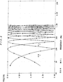
- Fig. 2 is a graph of the filter characteristics of the comb filters shown in Fig. 1.
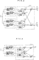
- Fig. 3 is a block diagram of a second embodiment of the surround signal processing apparatus of the present invention.
- Fig. 4 is a block diagram of a third embodiment of the surround signal processing apparatus of the present invention.
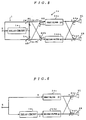
- Fig. 5 is a block diagram of a fourth embodiment of the surround signal processing apparatus of the present invention.
- Fig. 6 is a block diagram of a fifth embodiment of the surround signal processing apparatus of the present invention.
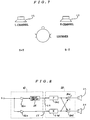
- Fig. 7 is a diagram showing the localized positions when a rear surround virtual sound image is localized from a pair of loudspeakers placed in substantially laterally- symmetrical locations in front of a listener.
- Fig. 8 is a block diagram of a sixth embodiment of the surround signal processing apparatus of the present invention.
- Fig. 9 is a block diagram of a seventh embodiment of the surround signal processing apparatus of the present invention.
- Fig. 10 is a block diagram of an eighth embodiment of the surround signal processing apparatus of the present invention.
- Fig. 1 is a block diagram of a first embodiment of the surround signal processing apparatus of the present invention.
- item 1 is a comb filter that, in a multi-channel sound reproduction system that employs monaural rear surround sound reproduction, functions as a signal processing means that adds a delay to a monaural rear surround signal S (hereinafter referred to simply as a "surround signal”) which is supplied to it after its level has been adjusted by a master level controller (not shown), and produces therefrom, signals that are the sum and difference signals of the "base” (pre-delay) signal and the delayed signal, which it outputs as two-channel rear surround signals.
- a monaural rear surround signal S hereinafter referred to simply as a "surround signal”
- the comb filter1 has a delay circuit 1a that adds a delay (in a range, for example, of 0 - 20 ms) to the input surround signal S, and outputs it as delay signal T; a summing circuit 1b that obtains a sum signal (S + T) by adding delay signal T to base surround signal S, and outputs the result as the L channel rear surround signal SL; and a subtraction circuit 1c that obtains a difference signal (S - T), by subtracting delay signal T from base surround signal S, and outputs the result as the R channel rear surround signal SR.
- a delay circuit 1a that adds a delay (in a range, for example, of 0 - 20 ms) to the input surround signal S, and outputs it as delay signal T
- a summing circuit 1b that obtains a sum signal (S + T) by adding delay signal T to base surround signal S, and outputs the result as the L channel rear surround signal SL
- a subtraction circuit 1c that obtains
- Fig. 2 is a graph of output signal amplitude characteristics, that explains the effect obtained in comb filter 1, which delays surround signal S and produces sum and difference signals from the delayed and base signals, and outputs the resulting signals as 2-channel rear surround signals, as described above.
- item 2 is a sound image localization circuit for performing a process to localize the sound image for each side to specific locations to the side and rear of the listener. It does this by performing additional summing of the filter processing results of each of the 2-channel rear surround signals SL and SR from comb filter 1.
- Items 3L and 3R in the drawing represent loudspeakers placed to the left and right in front of the listener.
- sound image localization circuit 2 Provided in sound image localization circuit 2, as previously proposed by this inventor in Japanese patent application H5(1993)-208871, are, in each of two separate rear surround signal channels SL and SR, an L-channel sound image localization circuit having left- and right-side sound image localization filters 21a and 21b, each of which have one of a pair of convolvers defined to have transfer functions Hl and Hr based on human head-related transfer functions for locations to the rear of, and substantially laterally-symmetrical with respect to, the listener, a similar R-channel sound image localization circuit having right-and left-side sound localization filters 21c and 21d, an adder 21e that sums the outputs of left-side filters 21a and 21d, and an adder 21f that sums the outputs of right-side filters 21b and 21a. Also, the signals, having been output from sound image localization circuit 2 and localized to specific rear locations, are reproduced as sound by the pair of front speakers 3L and 3R.
- S is the transfer characteristic from one speaker of speaker pair 3L/3R to the listener's ear on the same side as the speaker
- A is the transfer characteristic from one speaker of speaker pair 3L/3R to the listener's ear on the side opposite the speaker
- F is the transfer characteristic from a location (on either side) to which the surround signal is to be localized, to the listener's ear on the same side
- K is the transfer characteristic a the location (on either side) to which the surround signal is to be localized, to the listener's ear on the opposite side.
- Loudspeakers are placed at specific locations in an anechoic space, measurement data is taken from microphones positioned at both ears of a human (or dummy) head, and the measured data is then subjected to appropriate waveform processing.
- the term “same side” denotes, for example, the right ear for the right-hand speaker; while the term “opposite side” denotes, for example, the left ear for the right-hand speaker.
- base surround signal S separation in the frequency spectrum of the left and right components of base surround signal S is accomplished by feeding base surround signal S through comb filter 1, thereby obtaining the 2-channel (left and right) rear surround signals SL and SR having low correlation between channels.
- sound image localization circuit 2 the signals are subjected to further filter processing and the results summed, to localize each signal image to the rear.
- the system is arranged such that these sound-image-localized signals are reproduced as sound by a single pair of front speakers 3L and 3R.
- the rear sound can be localized into left-rear and right-rear virtual sound images, and the correlation between the two can be made to range from no correlation to weak correlation, thus obtaining extremely good surround sound, and in particular, a surround space can be created, that is natural and evokes a heightened sense of expansiveness.
- Fig. 3 is a block diagram of a second embodiment of the surround signal processing apparatus of the present invention.
- the configuration of the second embodiment shown in Fig.3 is a modified version of the first embodiment described above.
- rear surround signals SL and SR after having passed through comb filter 1, are further filtered in sound image localization processor circuit 2, and the filtered results summed, thus localizing the sound image of each signal to the rear, after which the resulting sound-image-localized signals are reproduced by a pair of front speakers, 3L and 3R.
- the signal is first sound-image-localized by an L-channel sound localization circuit having left- and right-side sound image localization filter pair 21a and 21b, and by an R-channel sound localization circuit having right- and left-side sound image localization filter pair 21c and 21d (which are the same as the same-numbered circuits in the first embodiment), after which the resulting signals are fed through comb filter 12 to render them as 2-channel rear surround signals having low left-right correlation, which are reproduced by a pair of front speakers, 3L and 3R.
- the mentioned comb filter 12 comprises: delay circuits 12a through 12d, which provide delayed version of the outputs they receive from the filters in each of the L-channel and R-channel sound image localization circuits; adders 12e and 12f, which add the signals fed through delay circuits 12a and 12b, respectively, to the pre-delay versions of the same signals, to obtain sum signals; subtractors 12g and 12h, which take the difference between the signals fed through delay circuits 12c and 12d, respectively, and the pre-delay versions of the same signals, to obtain difference signals; adder 12i, which outputs a sum signal obtained by adding the output of adder 12e to the output of subtractor 12g; and adder 12j, which outputs a sum signal obtained by adding the output of adder 12f to the output of subtractor 12h.
- surround signals that have been sound-image-localized by L-channel and R-channel sound image localization circuits are processed by comb filter 12 to obtain 2-channel rear surround signals having low left-right correlation, which are then reproduced by a pair of front speakers 3L and 3R. Therefore, as in the first embodiment, the rear sound can be localized into left-rear and right-rear virtual sound images, and the correlation between the two can be made to range from no correlation to weak correlation, thus obtaining extremely good surround sound, and in particular, a surround space can be created that is natural and evokes a heightened sense of expansiveness.
- Fig. 4 is a block diagram of a third embodiment of the surround signal processing apparatus of the present invention. As shown in Fig. 4, in this third embodiment, fewer delay circuits are used in the comb filter than were used in the second embodiment shown in Fig. 3. This, in turn, simplifies the sound image localization circuit filter configuration, in a system configuration that is the functional equivalent of that in the second embodiment.
- comb filter 13 comprises delay circuits 13a and 13b, which provide delayed versions of the outputs they receive from their associated sound image localization circuit filters; adders 13c and 13d, which add the signals fed through delay circuits 13a and 13b, respectively, to the pre-delay versions of the same signals, and output sum signals; subtractors 13e and 13f, which take the difference of the signals fed through delay circuits 13a and 13b, respectively, and the pre-delay versions of the same signals, and output difference signals; adder 13g, which outputs a sum signal obtained by adding the output of adder 13c to the output of subtractor 13f; and adder 13h, which outputs a sum signal obtained by adding the output of adder 13d to the output of subtractor 13e.
- the left and right sound image localization filters 21c and 21d used for two-speaker sound reproduction in the second embodiment shown in Fig. 3 can also be omitted, thus reducing this circuit to only the two left and right sound image localization filters 21a and 21b.
- Fig. 5 is a block diagram of a fourth embodiment of the surround signal processing apparatus of the present invention.
- sound image localization circuit 2 of the first embodiment, shown in Fig. 1 is simplified through the use of shuffler filters(see Duane H. Cooper and Jerald L. Bauck, "Prospects for Transaural Recording", J. Audio Eng. Soc., Vol. 37, No. 1/2, 1989 January/February, pp.3-9).
- sound image localization circuit 24 comprises: adder 24a, which adds sum signal (S + T), the sum of the 2-channel rear surround signals SL and SR (sum signals obtained by adding versions of surround signal S that have been delayed by different amounts) received from comb filter 1, to the corresponding difference signal (S - T); subtractor 24b, which takes the difference between sum signal (S + T) and difference signal (S - T); first filter 24c, which has a transfer characteristic P (to be discussed later) and which receives the output of adder 24a as its input, on which it performs convolution, etc.; second filter 24d, which has a transfer characteristic N (to be discussed later) and receives the output of subtractor 24b as its input, on which it performs convolution, etc.; subtractor 24e, which outputs the difference of the outputs of first and second filters 24c and 24d; and adder 24f, which adds the outputs of first and second filters 24c and 24d.
- the cross-talk that is, the sound from left speaker 3L that circles into the listener's right ear, and that from the right speaker 3R that circles into the listener's left ear, will be canceled, with the result that only the sound from the left speaker can be heard in the listener's left ear, and only the sound from the right speaker can be heard in the listener's right ear, and in addition, the processing in accordance with transfer characteristics F and K will result in sound images being localized at specific substantially laterally symmetrical locations to the rear of the listener.
- Fig. 6 is a block diagram of a fifth embodiment of the surround signal processing apparatus of the present invention. As shown in Fig. 6, the configuration of this fifth embodiment is the functional equivalent of that of the fourth embodiment, shown in Fig. 5.
- the fifth embodiment as in the fourth embodiment shown in Fig. 5 and discussed above, there are only two front speakers, and Shuffler filters are used in the sound image localization circuit to localize rear surround signals SL and SR to specific laterally symmetrical locations to the rear of the listener.
- the Shuffler filter portion of the fourth embodiment the sum and difference signals of the two input signals are taken, and the resulting signals fed through first and second filters 24c and 24d, having transfer characteristics P and N, respectively, to localize their sound images to the desired locations.
- the two input signals are (S + T) and (S - T), and their sum and difference signals are 2S and 2T, respectively.
- the signals being processed here would be S and T. Since the only difference between the original S and T signals, however, was in a delay or a lack of it, these S and T signals could be obtained by simply making "with delay” and “without delay” input signals, and the filter processing then performed on these signals.
- a surround signal S that has been delayed about 20 ms, is injected into first filter 24c, and that same signal S fed through delay circuit 1a to obtain a signal T, delayed by about (20 + 5) ms, which is then input into second filter 24d.
- Fig. 8 is a block diagram of a sixth embodiment of the surround signal processing apparatus of the present invention.
- this sixth embodiment as shown in Fig. 8, when performing the signal processing expressed by equations 5.1 and 5.2, above, in addition, to enhance the sense of expansiveness of the sound field, an amplitude difference is also established between the signals input to first and second filters 24c and 24d.
- amplitude adjustment amplifier 26a is provided ahead of delay circuit 25 on the first filter 24c input side, as an amplitude adjustment means for establishing an amplitude difference between the left and right surround signals.
- amplitude adjustment amplifier 26b is provided on the second filter 24d input side, and the amplitude adjustment ratios (gain) of amplitude adjustment amplifiers 26a and 26b adjusted to provide the desired amplitude difference.
- the desired sense of expansiveness can be retained while at the same time avoiding the characteristic unnatural sense of localization associated with phase inversion.
- non-correlation between signals is effected by introducing a time difference between the two rear surround signals, thus creating a pair of pseudo-stereophonic rear surround signals.
- the delaying means that provides this time difference is delay circuit 25, which is set, for example, for a delay of 5 ms (milliseconds).
- an amplitude difference between channels is effected by setting the amplitude adjustment ratios of amplitude adjustment amplifiers 26a and 26b such that signal level input to first filter 24c of sound image localization circuit 20 is about 2 dB down with respect to that at second filter 24d.
- This provides an input to the second filter 24d channel that is not only time-delayed with respect to the other channel(that is a precedence effect), but also has a different amplitude.
- the end result is the reproduction of a sound field that has a highly effective sense of expansiveness.
- Fig. 8 shows delay circuit 25 in the first filter 24c channel, it could also be in the second filter 24d channel.
- Fig. 9 is a block diagram of a seventh embodiment of the surround signal processing apparatus of the present invention. As shown in Fig. 9, this seventh embodiment, improves on configuration in Fig. 8 by providing delay circuits 25a and 25b, as delay circuits for the input stages of first and second filters 24c and 24d, respectively.
- This configuration enables the time delays of first and second filters 24c and 24d to be set in any desired relationship. Since the channel amplitudes can also be set as desired, the time delay and amplitude relationships can be set as desired for the best effect.
- the input levels of filters 24c and 24d can be changed, for example, to match the particular listening room environment.
- the first filter 24c channel input level could be increased by an appropriate amount to soften the sense of phase inversion, and for a live room, the same channel input could be lowered to sharpen the clarity of the virtual image.
- a variety of sound fields can be created in this manner.
- DSP digital signal processing
- the sound field can be enlarged using reflected sound adder circuit 50 to add reflected sound signal components to a pair of pseudo-stereophonic rear surround signals.
- Reflected sound adder circuit 50 accomplishes this by properly adjusting the amplitude of multiple rear surround signals, each delayed by a different amount, and then summing the resulting signals.
- This reflected sound adder circuit 50 adds a reflected sound component to, and outputs, a pair of pseudo-stereophonic rear surround signals. It does this by taking multiple rear surround signals S having different delay times from a delay line 25c used as a delaying means, appropriately adjusting the amplitudes of these multiple rear surround signals S in amplitude adjustment amplifiers 51, and then summing the resulting signals in adders 52.
Landscapes
- Physics & Mathematics (AREA)
- Engineering & Computer Science (AREA)
- Acoustics & Sound (AREA)
- Signal Processing (AREA)
- Stereophonic System (AREA)
Applications Claiming Priority (6)
| Application Number | Priority Date | Filing Date | Title |
|---|---|---|---|
| JP7028665A JP2985704B2 (ja) | 1995-01-25 | 1995-01-25 | サラウンド信号処理装置 |
| JP2866595 | 1995-01-25 | ||
| JP28665/95 | 1995-01-25 | ||
| JP16158395 | 1995-06-06 | ||
| JP161583/95 | 1995-06-06 | ||
| JP7161583A JP2953347B2 (ja) | 1995-06-06 | 1995-06-06 | サラウンド信号処理装置 |
Publications (3)
| Publication Number | Publication Date |
|---|---|
| EP0724378A2 true EP0724378A2 (de) | 1996-07-31 |
| EP0724378A3 EP0724378A3 (de) | 1998-07-29 |
| EP0724378B1 EP0724378B1 (de) | 2005-11-23 |
Family
ID=26366802
Family Applications (1)
| Application Number | Title | Priority Date | Filing Date |
|---|---|---|---|
| EP96100990A Expired - Lifetime EP0724378B1 (de) | 1995-01-25 | 1996-01-24 | Verarbeitungsvorrichtung für Raumklangsignale |
Country Status (3)
| Country | Link |
|---|---|
| US (1) | US5844993A (de) |
| EP (1) | EP0724378B1 (de) |
| DE (1) | DE69635466T2 (de) |
Cited By (2)
| Publication number | Priority date | Publication date | Assignee | Title |
|---|---|---|---|---|
| WO1999041947A1 (en) * | 1998-02-13 | 1999-08-19 | Koninklijke Philips Electronics N.V. | Surround sound reproduction system, sound/visual reproduction system, surround signal processing unit and method for processing an input surround signal |
| US6449368B1 (en) | 1997-03-14 | 2002-09-10 | Dolby Laboratories Licensing Corporation | Multidirectional audio decoding |
Families Citing this family (17)
| Publication number | Priority date | Publication date | Assignee | Title |
|---|---|---|---|---|
| US6052470A (en) * | 1996-09-04 | 2000-04-18 | Victor Company Of Japan, Ltd. | System for processing audio surround signal |
| KR100238668B1 (ko) * | 1996-11-28 | 2000-01-15 | 윤종용 | 디지털 비디오 재생장치 |
| JP3906533B2 (ja) * | 1997-11-04 | 2007-04-18 | ヤマハ株式会社 | 擬似ステレオ回路 |
| JP3513850B2 (ja) * | 1997-11-18 | 2004-03-31 | オンキヨー株式会社 | 音像定位処理装置および方法 |
| US6956954B1 (en) * | 1998-10-19 | 2005-10-18 | Onkyo Corporation | Surround-sound processing system |
| WO2001060118A1 (en) * | 2000-02-11 | 2001-08-16 | Tc Electronic A/S | Audio center channel phantomizer |
| US7433483B2 (en) | 2001-02-09 | 2008-10-07 | Thx Ltd. | Narrow profile speaker configurations and systems |
| US7254239B2 (en) * | 2001-02-09 | 2007-08-07 | Thx Ltd. | Sound system and method of sound reproduction |
| EP1251717A1 (de) * | 2001-04-17 | 2002-10-23 | Yellowknife A.V.V. | Verfahren und Schaltung zum anhören einer Audio-Aufzeichnung mit Kopfhörer |
| JP4016681B2 (ja) * | 2002-03-18 | 2007-12-05 | ヤマハ株式会社 | 効果付与装置 |
| JP3916087B2 (ja) * | 2004-06-29 | 2007-05-16 | ソニー株式会社 | 疑似ステレオ化装置 |
| ES2333137T3 (es) * | 2004-07-14 | 2010-02-17 | Koninklijke Philips Electronics N.V. | Conversion de canal de audio. |
| US20100100372A1 (en) * | 2007-01-26 | 2010-04-22 | Panasonic Corporation | Stereo encoding device, stereo decoding device, and their method |
| JP5867672B2 (ja) | 2011-03-30 | 2016-02-24 | ヤマハ株式会社 | 音像定位制御装置 |
| JP6301885B2 (ja) * | 2015-08-31 | 2018-03-28 | 日東電工株式会社 | 光学補償層付偏光板およびそれを用いた有機elパネル |
| US10251012B2 (en) * | 2016-06-07 | 2019-04-02 | Philip Raymond Schaefer | System and method for realistic rotation of stereo or binaural audio |
| CN111406414B (zh) * | 2017-12-01 | 2022-10-04 | 株式会社索思未来 | 信号处理装置以及信号处理方法 |
Family Cites Families (14)
| Publication number | Priority date | Publication date | Assignee | Title |
|---|---|---|---|---|
| US3746972A (en) * | 1970-02-16 | 1973-07-17 | Republic Steel Corp | Billet scanning mechanism using a probe carrying drum rotatable about the billet and pivotably mounted relative thereto |
| US3670106A (en) * | 1970-04-06 | 1972-06-13 | Parasound Inc | Stereo synthesizer |
| US4076959A (en) * | 1976-10-08 | 1978-02-28 | General Motors Corporation | Volume, tone and balance control for multi-channel audio systems |
| US4159397A (en) * | 1977-05-08 | 1979-06-26 | Victor Company Of Japan, Limited | Acoustic translation of quadraphonic signals for two- and four-speaker sound reproduction |
| JPS5931279B2 (ja) * | 1979-06-19 | 1984-08-01 | 日本ビクター株式会社 | 信号変換回路 |
| NL8303945A (nl) * | 1983-11-17 | 1985-06-17 | Philips Nv | Inrichting voor het realiseren van een pseudo-stereo signaal. |
| JP2580117B2 (ja) * | 1985-12-18 | 1997-02-12 | ソニー株式会社 | 再生装置における音場拡大装置 |
| US4783814A (en) * | 1986-10-09 | 1988-11-08 | Comprehensive Health Care Corp. Of America | Stethoscope having pseudostereophonic binaural enhancement |
| US5056149A (en) * | 1987-03-10 | 1991-10-08 | Broadie Richard G | Monaural to stereophonic sound translation process and apparatus |
| JPH03163999A (ja) * | 1989-08-05 | 1991-07-15 | Matsushita Electric Ind Co Ltd | 音響再生装置 |
| JPH05207597A (ja) * | 1992-01-30 | 1993-08-13 | Matsushita Electric Ind Co Ltd | 音場再生装置 |
| US5572591A (en) * | 1993-03-09 | 1996-11-05 | Matsushita Electric Industrial Co., Ltd. | Sound field controller |
| JP3463313B2 (ja) * | 1993-04-06 | 2003-11-05 | ヤマハ株式会社 | 音場生成回路 |
| DE69433258T2 (de) * | 1993-07-30 | 2004-07-01 | Victor Company of Japan, Ltd., Yokohama | Raumklangsignalverarbeitungsvorrichtung |
-
1996
- 1996-01-24 EP EP96100990A patent/EP0724378B1/de not_active Expired - Lifetime
- 1996-01-24 US US08/590,497 patent/US5844993A/en not_active Expired - Lifetime
- 1996-01-24 DE DE69635466T patent/DE69635466T2/de not_active Expired - Lifetime
Cited By (3)
| Publication number | Priority date | Publication date | Assignee | Title |
|---|---|---|---|---|
| US6449368B1 (en) | 1997-03-14 | 2002-09-10 | Dolby Laboratories Licensing Corporation | Multidirectional audio decoding |
| WO1999041947A1 (en) * | 1998-02-13 | 1999-08-19 | Koninklijke Philips Electronics N.V. | Surround sound reproduction system, sound/visual reproduction system, surround signal processing unit and method for processing an input surround signal |
| US6292570B1 (en) | 1998-02-13 | 2001-09-18 | U.S. Philips Corporation | Surround sound |
Also Published As
| Publication number | Publication date |
|---|---|
| EP0724378B1 (de) | 2005-11-23 |
| DE69635466D1 (de) | 2005-12-29 |
| US5844993A (en) | 1998-12-01 |
| EP0724378A3 (de) | 1998-07-29 |
| DE69635466T2 (de) | 2006-08-17 |
Similar Documents
| Publication | Publication Date | Title |
|---|---|---|
| US5844993A (en) | Surround signal processing apparatus | |
| US6937737B2 (en) | Multi-channel audio surround sound from front located loudspeakers | |
| EP0966865B1 (de) | Mehrweg-audiodekoder | |
| EP1040466B1 (de) | Raumklangsignalverarbeitungsvorriehtung und -verfahren | |
| US6504933B1 (en) | Three-dimensional sound system and method using head related transfer function | |
| US8605914B2 (en) | Nonlinear filter for separation of center sounds in stereophonic audio | |
| EP0880301A2 (de) | Gesamttonhervorhebung unter Verwendung von mehreren Toneingangssignalen | |
| US20110026718A1 (en) | Virtualizer with cross-talk cancellation and reverb | |
| KR100437174B1 (ko) | 스테레오음향시스템 | |
| JP2002262398A (ja) | ヘッドホン用立体音響装置および音声信号処理プログラム | |
| JP3219752B2 (ja) | 疑似ステレオ化装置 | |
| JPWO1999035886A1 (ja) | 疑似ステレオ化装置 | |
| JP2944424B2 (ja) | 音響再生回路 | |
| JPH07123498A (ja) | ヘッドホン再生システム | |
| EP1021062A2 (de) | Verfahren und Vorrichtung zur Wiedergabe von mehrkanaligen Audiosignalen | |
| NL1032538C2 (nl) | Apparaat en werkwijze voor het reproduceren van virtueel geluid van twee kanalen. | |
| JP2985704B2 (ja) | サラウンド信号処理装置 | |
| JP2953347B2 (ja) | サラウンド信号処理装置 | |
| EP1815716A1 (de) | Vorrichtung und verfahren zur verarbeitung von mehrkanal-audioeingangssignalen zur erzeugung von mindestens zwei kanalausgangssignalen daraus sowie computerlesbares medium mit ausführbarem code zur durchführung dieses verfahrens | |
| EP1212923B1 (de) | Verfahren und anordnung zur erzeugung eines zweiten audiosignales von einem ersten audiosignal | |
| JP3700254B2 (ja) | 映像音声再生装置 | |
| JPH11113098A (ja) | マルチチャンネル音声信号の2チャンネルエンコード処理装置 | |
| JPS5814798B2 (ja) | 立体音場拡大装置 | |
| JPH0795697A (ja) | サラウンド信号処理装置及び映像音声再生装置 | |
| JP3925633B2 (ja) | 音声再生装置 |
Legal Events
| Date | Code | Title | Description |
|---|---|---|---|
| PUAI | Public reference made under article 153(3) epc to a published international application that has entered the european phase |
Free format text: ORIGINAL CODE: 0009012 |
|
| AK | Designated contracting states |
Kind code of ref document: A2 Designated state(s): DE FR GB |
|
| PUAL | Search report despatched |
Free format text: ORIGINAL CODE: 0009013 |
|
| AK | Designated contracting states |
Kind code of ref document: A3 Designated state(s): DE FR GB |
|
| 17P | Request for examination filed |
Effective date: 19981209 |
|
| 17Q | First examination report despatched |
Effective date: 20030217 |
|
| GRAP | Despatch of communication of intention to grant a patent |
Free format text: ORIGINAL CODE: EPIDOSNIGR1 |
|
| GRAS | Grant fee paid |
Free format text: ORIGINAL CODE: EPIDOSNIGR3 |
|
| GRAA | (expected) grant |
Free format text: ORIGINAL CODE: 0009210 |
|
| AK | Designated contracting states |
Kind code of ref document: B1 Designated state(s): DE FR GB |
|
| REG | Reference to a national code |
Ref country code: GB Ref legal event code: FG4D |
|
| REF | Corresponds to: |
Ref document number: 69635466 Country of ref document: DE Date of ref document: 20051229 Kind code of ref document: P |
|
| ET | Fr: translation filed | ||
| PLBE | No opposition filed within time limit |
Free format text: ORIGINAL CODE: 0009261 |
|
| STAA | Information on the status of an ep patent application or granted ep patent |
Free format text: STATUS: NO OPPOSITION FILED WITHIN TIME LIMIT |
|
| 26N | No opposition filed |
Effective date: 20060824 |
|
| REG | Reference to a national code |
Ref country code: DE Ref legal event code: R082 Ref document number: 69635466 Country of ref document: DE Representative=s name: WAGNER & GEYER PARTNERSCHAFT PATENT- UND RECHT, DE |
|
| REG | Reference to a national code |
Ref country code: DE Ref legal event code: R082 Ref document number: 69635466 Country of ref document: DE Representative=s name: WAGNER & GEYER PARTNERSCHAFT MBB PATENT- UND R, DE Effective date: 20120430 Ref country code: DE Ref legal event code: R082 Ref document number: 69635466 Country of ref document: DE Representative=s name: WAGNER & GEYER PARTNERSCHAFT PATENT- UND RECHT, DE Effective date: 20120430 Ref country code: DE Ref legal event code: R081 Ref document number: 69635466 Country of ref document: DE Owner name: JVC KENWOOD CORPORATION, JP Free format text: FORMER OWNER: VICTOR COMPANY OF JAPAN, LTD., YOKOHAMA, JP Effective date: 20120430 Ref country code: DE Ref legal event code: R081 Ref document number: 69635466 Country of ref document: DE Owner name: JVC KENWOOD CORPORATION, YOKOHAMA-SHI, JP Free format text: FORMER OWNER: VICTOR COMPANY OF JAPAN, LTD., YOKOHAMA, KANAGAWA, JP Effective date: 20120430 |
|
| REG | Reference to a national code |
Ref country code: FR Ref legal event code: TP Owner name: JVC KENWOOD CORPORATION, JP Effective date: 20120705 |
|
| PGFP | Annual fee paid to national office [announced via postgrant information from national office to epo] |
Ref country code: FR Payment date: 20140108 Year of fee payment: 19 |
|
| PGFP | Annual fee paid to national office [announced via postgrant information from national office to epo] |
Ref country code: GB Payment date: 20140122 Year of fee payment: 19 |
|
| PGFP | Annual fee paid to national office [announced via postgrant information from national office to epo] |
Ref country code: DE Payment date: 20150120 Year of fee payment: 20 |
|
| GBPC | Gb: european patent ceased through non-payment of renewal fee |
Effective date: 20150124 |
|
| PG25 | Lapsed in a contracting state [announced via postgrant information from national office to epo] |
Ref country code: GB Free format text: LAPSE BECAUSE OF NON-PAYMENT OF DUE FEES Effective date: 20150124 |
|
| REG | Reference to a national code |
Ref country code: FR Ref legal event code: ST Effective date: 20150930 |
|
| PG25 | Lapsed in a contracting state [announced via postgrant information from national office to epo] |
Ref country code: FR Free format text: LAPSE BECAUSE OF NON-PAYMENT OF DUE FEES Effective date: 20150202 |
|
| REG | Reference to a national code |
Ref country code: DE Ref legal event code: R071 Ref document number: 69635466 Country of ref document: DE |