EP0724670B1 - Clous reflecteurs pour routes - Google Patents
Clous reflecteurs pour routes Download PDFInfo
- Publication number
- EP0724670B1 EP0724670B1 EP94930192A EP94930192A EP0724670B1 EP 0724670 B1 EP0724670 B1 EP 0724670B1 EP 94930192 A EP94930192 A EP 94930192A EP 94930192 A EP94930192 A EP 94930192A EP 0724670 B1 EP0724670 B1 EP 0724670B1
- Authority
- EP
- European Patent Office
- Prior art keywords
- base
- head
- overhang
- neck
- marker
- Prior art date
- Legal status (The legal status is an assumption and is not a legal conclusion. Google has not performed a legal analysis and makes no representation as to the accuracy of the status listed.)
- Expired - Lifetime
Links
- 239000003550 marker Substances 0.000 claims description 48
- 230000015572 biosynthetic process Effects 0.000 claims description 21
- 238000000034 method Methods 0.000 claims description 9
- 230000000630 rising effect Effects 0.000 claims description 2
- 239000012858 resilient material Substances 0.000 claims 1
- 210000003128 head Anatomy 0.000 description 24
- 238000005755 formation reaction Methods 0.000 description 20
- 239000000969 carrier Substances 0.000 description 9
- 238000001125 extrusion Methods 0.000 description 6
- 229910052751 metal Inorganic materials 0.000 description 5
- 239000002184 metal Substances 0.000 description 5
- 239000004411 aluminium Substances 0.000 description 3
- 229910052782 aluminium Inorganic materials 0.000 description 3
- XAGFODPZIPBFFR-UHFFFAOYSA-N aluminium Chemical compound [Al] XAGFODPZIPBFFR-UHFFFAOYSA-N 0.000 description 3
- 238000004519 manufacturing process Methods 0.000 description 3
- 241000282326 Felis catus Species 0.000 description 2
- 238000010586 diagram Methods 0.000 description 2
- 239000000463 material Substances 0.000 description 2
- 239000004033 plastic Substances 0.000 description 2
- 229920003023 plastic Polymers 0.000 description 2
- 239000000853 adhesive Substances 0.000 description 1
- 230000001070 adhesive effect Effects 0.000 description 1
- 238000005452 bending Methods 0.000 description 1
- 238000004512 die casting Methods 0.000 description 1
- 210000000887 face Anatomy 0.000 description 1
- 238000001746 injection moulding Methods 0.000 description 1
- 238000005065 mining Methods 0.000 description 1
- 239000004417 polycarbonate Substances 0.000 description 1
- 229920000515 polycarbonate Polymers 0.000 description 1
- 239000012260 resinous material Substances 0.000 description 1
Images


Classifications
-
- E—FIXED CONSTRUCTIONS
- E01—CONSTRUCTION OF ROADS, RAILWAYS, OR BRIDGES
- E01F—ADDITIONAL WORK, SUCH AS EQUIPPING ROADS OR THE CONSTRUCTION OF PLATFORMS, HELICOPTER LANDING STAGES, SIGNS, SNOW FENCES, OR THE LIKE
- E01F9/00—Arrangement of road signs or traffic signals; Arrangements for enforcing caution
- E01F9/50—Road surface markings; Kerbs or road edgings, specially adapted for alerting road users
- E01F9/553—Low discrete bodies, e.g. marking blocks, studs or flexible vehicle-striking members
Definitions
- THIS invention relates to markers for roads or pavements or so-called cat's eyes, according to the preamble of claim 1. It also relates to an extruded rigid body for a road marker according to the preamble of claim 8 and a method of producing a road marker according to the preamble of claim 9.
- the road markers known to the applicant suffer from at least one of the following disadvantages. These markers are primarily made by an injection moulding process of a suitable metal or synthetic resinous material which makes them and their moulds relatively expensive. Due to their structure and to ensure stable anchorage in the pavement or road surface, their reflector elements are located too close to the road surface, so that soiling of these elements occur. Furthermore, due to their structure, rocking of the marker occurs upon impact with a vehicle wheel, which causes the marker to become loose in the road structure.
- a road marker body comprising a base, a neck and a head integrally formed from a metal.
- the neck comprises parallel sidewalls extending from the base to the overhanging head. Reflectors are mounted adjacent the sidewalls. The reflectors are obscured by the overhanging head and ridge formations at the periphery of the base. Furthermore, as the cross-sectional area of the head is large compared to the size of the base, rocking of the marker upon impact with a vehicle wheel will occur. This rocking will eventually lead to dislodgement of the marker.
- a body for a road marker comprising a base, a neck and a head integrally formed from a metal.
- the neck comprises two opposed sidewalls slanting from a wide region of the neck adjacent the bass to a narrow region thereof adjacent the head. Reflectors are mounted adjacent the sloping sidewalls. The cross sectional area of the wide region of the neck is wide so that rocking of this marker will also occur when struck by vehicle wheels.
- a road marker with the features of claim 1. It comprises a body extruded from a rigid material and reflector means mounted on the body, the body comprising a base and interconnection means connecting the base to at least one overhang above the base, the reflector means being mounted between the overhang and the base, in use, to be exposed at an obtuse angle to approaching traffic.
- the marker may comprise a head formation and the interconnection means may comprise a neck formation extending away from the base to the head formation on another side of the base as a bottom surface of the base, at least part of the neck formation having a cross-sectional area in a plane parallel to said bottom surface less than a cross-sectional area of the head formation in a region thereof adjacent to the neck formation in a plane parallel to said bottom surface and also less than the cross-sectional area of said bottom surface, so that the body is substantially uniformly I-shaped in cross section and so that the head formation provides said at least one overhang above said base.
- the base may be rectangular and the neck formation may be elongated and may extend intermediate two opposed sides of the base from one end region of the base to an opposite end region of the base.
- Sides of the neck formation facing said opposed sides of the base may slant from a relatively wider region of the neck formation towards one another in a direction towards the head formation to a relatively narrower region of the neck formation and a cross-sectional area of the neck formation in said wider region thereof is less than 30% of that of the bottom surface of the base.
- Opposed ends of the elongate neck formation may slant towards one another in a direction towards the head formation.
- any cross sectional area of the head formation parallel to the bottom surface of the base is less than 25% of that of the bottom surface of the base.
- a top surface of the base may provide a rising ramp from each of said opposed sides of the base in a direction towards the neck formation.
- Opposed slots may be defined immediately adjacent the neck formation in the base and in said at least one overhang respectively, for locating said reflector means.
- the reflector means may comprise a disc received in said opposed slots and which disc carries a plurality of reflective elements.
- a plurality of slots may be provided in the bottom surface of the base to extend parallel to said opposed sides of the base, at least some of the slots having a dovetail shape in transverse cross-section with a narrower region of the slot located in a plane of the bottom surface of the base.
- Anchor means may be provided in the bottom surface of the base to extend in a direction opposite the neck formation.
- a body for a road marker has the features of claim 8.
- a method of producing a road marker has the features of claim 9.
- the reflector means may be secured to the body by mechanically arresting it on the body.
- the reflector means may be so arrested by local deformation of said at least one overhang beyond at least one end of said reflector means.
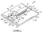
- a first embodiment of a cat's eye or road marker according to the invention is generally designated by the reference numeral 10.
- the marker 10 comprises a body 12 having a rectangular base 14 and an elongate head 16 interconnected by an elongate neck 18.
- the base 14, neck 18 and head 16 are integrally formed in a metal or rigid plastics extrusion 20 (shown in figure 3) and the marker body 12 is formed by severing it from the extrusion 20.
- the metal is preferably aluminium and the rigid plastic is preferably polycarbonate.
- the neck 18 extends between two opposed ends 14.1 of the base 14 and is located halfway between two opposed sides 14.2 thereof.
- the neck comprises two opposed elongate outer surfaces 18.1 and 18.2 sloping towards one another from a relatively wider region of the neck adjacent base 14 to a relatively narrower region adjacent head 16.
- the two opposed ends 18.3 of the neck 18 also slope inwardly towards one another.
- the transverse cross-sectional area of the neck 18 on line A is less than that of bottom surface 14.3 of base 14 and less than that of the head 16 in a region thereof adjacent neck 18 in a plane parallel to that of bottom surface 14.3. Accordingly, the body 12 has a uniform generally I-shape when sectioned and viewed on line B and lines parallel thereto.
- the base 14 defines a plurality of parallel dovetail shaped slots 22 in a bottom surface 14.3 thereof.
- the narrower ends of slots 22 lie in the plane of bottom surface 14.3.
- the base 14 provides ramps 14.4 extending away from the bottom surface 14.3 in a direction from the sides 14.2 of the base towards the neck 18.
- the minimum distance of the ramps 14.4 from the bottom surface 14.3 is typically 4mm and they form angles of in the order of 51° with the bottom surface 14.3.
- Carriers 26 for reflective elements 28 are removably and slidingly receivable in the open ended opposed slots to abut against surfaces 18.1 and 18.2 and to extend between the overhangs 16.1 and the base 14.
- the carriers 26 are mechanically arrested on the body by bending the overhanging regions 16.1 of the head outside the carriers 26 towards base 14.
- the markers are secured to a road surface (not shown) by a suitable adhesive which, when cured, forms a key in each of slots 22.
- threaded holes 30 In use, bolts 32 may be threaded into the holes 30 to serve as additional anchors for the markers 10 in the road or pavement structure.
- the body 12 is formed by severing a selected length L (100mm, 150mm, 200mm or 250mm or longer) from aluminium extrusion 20, thereby providing an integral structure. Thereafter the end regions 18.3 and 18.4 of the neck 18 and head 16 are machined away. As shown in figure 2, the dimension W of the body along end 14.1 of the base 14, is typically in the order of 100mm and the dimension of the aforementioned wider region N w of neck 18 is typically less than 30% thereof.
- the maximum cross sectional area of the head 16 in a plane parallel to the bottom surface 14.3 of the base is typically in the order of 20% of that of the rectangular area wherein bottom surface 14.3 of the base is located.
- a base 14 of 100mm x 100mm or 150mm or 200mm the distance between the top surface of the head and the bottom surface of the base is in the order of 22mm, according to the international standards.
- the method of manufacture and the marker 10 according to the invention and the marker system provide flexibility in that the marker size may easily be changed by severing shorter or longer bodies 12 from the extrusion 20. Furthermore, a large variety of known reflector carriers may easily and conveniently be mounted on the body, thereby to provide a customer with a wide selection at relatively low cost. Such reflector carriers include forty-three element carriers, twenty-three element carriers and seven element carriers of which the retro-reflective lenses may be any one of white, red, amber, green and blue in colour and which are being sold under the trade name "Swareflex".
- more than one reflector carrier 26 may be provided adjacent each of sidewalls 18.1 and 18.2 of the neck 18.
- FIG 4 there is shown a second embodiment of the marker body according to the invention designated 112 and which is substantially similar to the body 12 of figures 1 to 3, except that the neck 118 connecting head 116 to base 114 is not located halfway between the two opposed sides 114.2 of base 114, but is located substantially at one side of the base 114.
Landscapes
- Engineering & Computer Science (AREA)
- Architecture (AREA)
- Civil Engineering (AREA)
- Structural Engineering (AREA)
- Road Signs Or Road Markings (AREA)
- Aerials With Secondary Devices (AREA)
Claims (10)
- Organe (10) de marquage routier, comprenant :un corps rigide extrudé (12 ; 112), etun dispositif réflecteur (26, 28) monté sur le corps (12 ; 112),dans lequel le corps (12 ; 112) comporte une base (14, 114), un dispositif d'interconnexion (18 ; 118) et une tête (6, 116), formée en une seule pièce les uns avec les autres, dans lequel le dispositif d'interconnexion (18 ; 118) a une configuration inclinée et raccorde la base (14 ; 114) à la tête (16 ; 116), et dans lequel la tête (16 ; 116) a au moins une partie en surplomb (16.1) placée au-dessus de la base (14 ; 114), etdans lequel le dispositif réflecteur (26, 28) est monté entre la partie en surplomb (16.1) et la base (14 ; 114),
caractérisé en ce queune section de la tête (16 ; 116) est inférieure à 25 % de celle de la surface inférieure de la base (14 ; 114), etune section du dispositif incliné d'interconnexion (18 ; 118) dans la région relativement large adjacente à la base (14 ; 114) est inférieure à 30 % de celle de la surface inférieure (14.3) de la base (14 ; 114). - Organe de marquage routier selon la revendication 1, dans lequel la base (14) est rectangulaire, et dans lequel le dispositif d'interconnexion a la forme d'un col (18) qui est allongé et s'étend entre deux extrémités opposées (14.2) de la base (14) depuis une première région d'extrémité (14.1) de la base (14) vers une région opposée d'extrémité (14.1) de la base (14), des faces latérales opposées (18.1, 18.2) du col (18) étant tournées vers les deux côtés opposés (14.2) de la base (14).
- Organe de marquage routier selon la revendication 2, dans lequel les extrémités opposées (18.3, 18.4) du col allongé (18) sont inclinées l'une vers l'autre vers la tête (16).
- Organe de marquage routier selon la revendication 2 ou 3, dans lequel la surface supérieure de la base (14) forme une rampe ascendante (14.4) depuis chacun des côtés opposés (14.2) de la base (14) vers le col (18).
- Organe de marquage routier selon l'une quelconque des revendications 1 à 4, dans lequel les fentes (22) sont formées à la surface inférieure (14.3) de la base (14), chacune des fentes (22) ayant une forme en queue d'aronde en coupe transversale, avec une région relativement étroite de la fente (22) placée dans le plan de la surface inférieure (14.3) de la base (14).
- Organe de marquage routier selon l'une quelconque des revendications 1 à 5, dans lequel des fentes opposées (24.1, 24.2) sont délimitées en position immédiatement adjacente au col formé dans la base (14) et dans au moins une partie en surplomb (16.1) respectivement pour le positionnement du dispositif réflecteur (16, 28).
- Organe de marquage routier selon l'une quelconque des revendications 1 à 6, dans lequel le dispositif réflecteur (26, 28) comporte un disque (26) portant plusieurs éléments réfléchissants (28).
- Corps extrudé rigide (12 ; 112) destiné à un organe de marquage routier (10), comprenant :une base (14 ; 114), un dispositif d'interconnexion (18 ; 118) et une tête (16 ; 116) formés en une seule pièce les uns avec les autres,dans lequel le dispositif d'interconnexion (18 ; 118) a une configuration inclinée et raccorde la base (14 ; 114) à la tête (16 ; 116),dans lequel la tête (16 ; 116) a au moins une partie en surplomb (16.1) au-dessus de la base (14 ; 114), etdans lequel le corps délimite des fentes opposées dans la base (14 ; 114) et dans au moins une partie en surplomb (16.1) pour le logement du dispositif réflecteur (26, 28) de manière coulissante,
caractérisé en ce queune section de la tête (16 ; 116) est inférieure à 25 % de celle de la surface inférieure de la base (14 ; 114), etune section du dispositif incliné d'interconnexion (18 ; 118) dans la région relativement large adjacente à la base (14 ; 114) est inférieure à 30 % de celle de la surface inférieure (14.3) de la base (14 ; 114). - Procédé de production d'un organe de marquage routier (10), comprenant les étapes suivantes :l'extrusion d'un matériau non élastique sous forme d'un corps de marquage (12 ; 112) qui comporte une base (14 ; 114), un dispositif d'interconnexion (18 ; 118) et une tête (16 ; 116), formés en une seule pièce les uns avec les autres, dans lequel le dispositif d'interconnexion (18 ; 118) a une configuration inclinée et raccorde la base (14 ; 114) à la tête (16 ; 116), et dans lequel la tête (16 ; 116) possède au moins une partie en surplomb (16.1) au-dessus de la base (14 ; 114), etle montage d'un dispositif réflecteur (26, 28) sur le corps (12 ; 112) dans des fentes opposées (24.1, 24.2) délimitées dans la base (14 ; 114) et dans la partie en surplomb au moins (16.1),
caractérisé par l'étape supplémentaire suivante :l'arrêt mécanique du dispositif réflecteur (26, 28) sur le corps (12 ; 112) par déformation locale du corps (12 ; 112) afin que l'une au moins des fentes opposées (24.1, 24.2) soit bouchée,dans lequel une section de la tête (16 ; 116) est inférieure à 25 % de celle de la surface inférieure de la base (14 ; 114), etdans lequel une section du dispositif incliné d'interconnexion (18 ; 118) dans la région relativement large adjacente à la base (14 ; 114) est inférieure à 30 % de celle d'une surface inférieure (14.3) de la base (14 ; 114). - Procédé selon la revendication 9, dans lequel le dispositif réflecteur (26, 28) est arrêté mécaniquement par déformation locale de la partie en surplomb au moins (16.1) au-delà du dispositif réflecteur (26, 28) afin que la fente (24.2) délimitée dans la partie en surplomb (16.1) soit bouchée.
Applications Claiming Priority (3)
| Application Number | Priority Date | Filing Date | Title |
|---|---|---|---|
| ZA937783 | 1993-10-20 | ||
| ZA9307783 | 1993-10-20 | ||
| PCT/EP1994/003440 WO1995011347A1 (fr) | 1993-10-20 | 1994-10-19 | Clous reflecteurs pour routes |
Publications (2)
| Publication Number | Publication Date |
|---|---|
| EP0724670A1 EP0724670A1 (fr) | 1996-08-07 |
| EP0724670B1 true EP0724670B1 (fr) | 2000-02-02 |
Family
ID=25583333
Family Applications (1)
| Application Number | Title | Priority Date | Filing Date |
|---|---|---|---|
| EP94930192A Expired - Lifetime EP0724670B1 (fr) | 1993-10-20 | 1994-10-19 | Clous reflecteurs pour routes |
Country Status (9)
| Country | Link |
|---|---|
| US (1) | US5857802A (fr) |
| EP (1) | EP0724670B1 (fr) |
| CN (1) | CN1113135C (fr) |
| AP (1) | AP483A (fr) |
| AU (1) | AU687105B2 (fr) |
| BR (1) | BR9407884A (fr) |
| DE (1) | DE69422929T2 (fr) |
| WO (1) | WO1995011347A1 (fr) |
| ZA (1) | ZA948230B (fr) |
Families Citing this family (9)
| Publication number | Priority date | Publication date | Assignee | Title |
|---|---|---|---|---|
| US6428238B2 (en) | 1996-10-11 | 2002-08-06 | Pac-Tec, Inc. | Road marker collar |
| US6200064B1 (en) * | 1996-10-11 | 2001-03-13 | Pac-Tec, Inc. | Road marker with collar |
| US6102612A (en) * | 1998-06-16 | 2000-08-15 | Stimsonite Corporation | Controlled tire impact pavement marker |
| US6164865A (en) * | 1998-09-14 | 2000-12-26 | Mccallum; Gerald L. | Interlocking barrier system with multiple securing mechanisms |
| US6991400B1 (en) * | 2001-02-15 | 2006-01-31 | Negueloua Gerald I | Cap sealer for caulked joints |
| US20030059256A1 (en) * | 2001-09-27 | 2003-03-27 | Thomas Gallup | Solid pavement marker |
| US6955497B2 (en) * | 2003-05-21 | 2005-10-18 | Avery Dennison Corporation | Pavement marker |
| US20170002526A1 (en) * | 2014-01-21 | 2017-01-05 | Ignácio HERNÁNDEZ SANTACRUZ | Reflectors |
| CN111655932A (zh) | 2018-01-30 | 2020-09-11 | 3M创新有限公司 | 反光的凸起路面标记物及其制造方法 |
Family Cites Families (34)
| Publication number | Priority date | Publication date | Assignee | Title |
|---|---|---|---|---|
| DE873224C (de) * | 1951-11-09 | 1953-04-13 | Ernst Michel | Vorrichtung zur Verkehrssicherung mit Hilfe von Rueckstrahlern |
| CH323261A (fr) * | 1954-07-23 | 1957-07-31 | Polva Maroc S A | Elément marqueur destiné à être ancré dans la surface d'un sol, tel qu'une chaussée, et procédé de fabrication de l'élément marqueur |
| CH375747A (de) * | 1960-03-17 | 1964-03-15 | Leu Hans | Strassenmarkierung |
| DE1709463A1 (de) * | 1967-07-21 | 1976-08-26 | Amerace Corp | Strassenmarkierung |
| US3485148A (en) * | 1968-06-25 | 1969-12-23 | Amerace Esna Corp | Pavement markers with selectively replaceable reflectors |
| US3971623A (en) * | 1975-03-13 | 1976-07-27 | International Tools (1973) Ltd. | Roadway marker |
| US3975108A (en) * | 1975-06-09 | 1976-08-17 | Itl Industries, Inc. | Snow plowable pavement marker |
| GB1531793A (en) * | 1977-04-22 | 1978-11-08 | Indigrade Ltd | Road studs |
| US4232979A (en) * | 1978-12-18 | 1980-11-11 | Amerace Corporation | Pavement marker |
| DE7902220U1 (de) * | 1979-01-27 | 1980-07-03 | H. Debuschewitz Gmbh & Co Kg, 5000 Koeln | Bodenrueckstrahler |
| US4358217A (en) * | 1979-03-05 | 1982-11-09 | Stone Walter E | Highway traffic lane and road edge reflectors |
| US4428320A (en) * | 1981-06-08 | 1984-01-31 | Lukens General Industries, Inc. | Reflective paving marker |
| US4659248A (en) * | 1981-11-17 | 1987-04-21 | Amerace Corporation | Self cleaning pavement marker |
| US4445803A (en) * | 1982-12-17 | 1984-05-01 | Dixon Byron P | Resilient marker |
| US4521129A (en) * | 1983-06-17 | 1985-06-04 | Minnesota Mining And Manufacturing Company | Elastomeric pavement marker having improved configuration |
| US4534673A (en) * | 1983-04-11 | 1985-08-13 | Minnesota Mining And Manufacturing Company | Elastomeric pavement marker |
| CA1207174A (fr) * | 1984-02-14 | 1986-07-08 | Ronald A.W. Clarke | Dispositif de demarcation routiere, et son logement |
| US4594021A (en) * | 1984-04-23 | 1986-06-10 | Schaefer Hartmut | Marker block for divisions on trafficways in form of an oblong beam-like body and having reflective means |
| US4577992A (en) * | 1984-08-31 | 1986-03-25 | Jefferies George S | Snowplowable road marker apparatus |
| US4618281A (en) * | 1984-12-31 | 1986-10-21 | Ajemian Van R | Raised pavement marker brace |
| US4653955A (en) * | 1986-05-07 | 1987-03-31 | Ferro Corporation | Retroreflective device having curved retroreflective surface |
| US4726706A (en) * | 1986-06-02 | 1988-02-23 | Attar Adil H | Reflective pavement marker |
| US4815890A (en) * | 1986-08-26 | 1989-03-28 | Duncan Terence J | Low level traffic direction pavement marker |
| US4753548A (en) * | 1986-09-29 | 1988-06-28 | Pac-Tec, Inc. | Abrasive resistant pavement marker |
| US4797024A (en) * | 1986-09-29 | 1989-01-10 | Pac-Tec, Inc. | Abrasive resistant pavement marker |
| US4717281A (en) * | 1986-10-10 | 1988-01-05 | Shepherd Kathleen P | Road marker system and method of installation |
| US4883384A (en) * | 1988-12-14 | 1989-11-28 | Pac-Tec, Inc. | Protective roadway marker guard rails |
| US5061114A (en) * | 1990-02-05 | 1991-10-29 | Pac-Tec, Inc. | Reflective pavement marker and method of apparatus for making same |
| US5098217A (en) * | 1990-05-23 | 1992-03-24 | Pac-Tec, Inc. | Abrasion resistant coating for pavement marker |
| AU639369B2 (en) * | 1990-09-28 | 1993-07-22 | Hardman Catseye Pty Ltd | A pavement marker |
| US5104256A (en) * | 1990-10-17 | 1992-04-14 | Highway Ceramics, Inc. | Low profile pavement marker |
| US5240344A (en) * | 1990-10-19 | 1993-08-31 | Green William P | Road or street lane markers |
| US5327850A (en) * | 1991-05-02 | 1994-07-12 | Davidson Plastics Company | Roadway marker |
| US5173099A (en) * | 1991-05-30 | 1992-12-22 | Chen Hung Chun | Process for manufacturing road warning device for divided driveway |
-
1994
- 1994-10-19 US US08/632,396 patent/US5857802A/en not_active Expired - Fee Related
- 1994-10-19 WO PCT/EP1994/003440 patent/WO1995011347A1/fr not_active Ceased
- 1994-10-19 EP EP94930192A patent/EP0724670B1/fr not_active Expired - Lifetime
- 1994-10-19 DE DE69422929T patent/DE69422929T2/de not_active Expired - Fee Related
- 1994-10-19 AP APAP/P/1994/000688A patent/AP483A/en active
- 1994-10-19 BR BR9407884A patent/BR9407884A/pt not_active IP Right Cessation
- 1994-10-19 AU AU79384/94A patent/AU687105B2/en not_active Ceased
- 1994-10-20 CN CN94118699A patent/CN1113135C/zh not_active Expired - Lifetime
- 1994-10-20 ZA ZA948230A patent/ZA948230B/xx unknown
Also Published As
| Publication number | Publication date |
|---|---|
| US5857802A (en) | 1999-01-12 |
| AU687105B2 (en) | 1998-02-19 |
| CN1113135C (zh) | 2003-07-02 |
| ZA948230B (en) | 1995-06-12 |
| WO1995011347A1 (fr) | 1995-04-27 |
| BR9407884A (pt) | 1996-10-29 |
| EP0724670A1 (fr) | 1996-08-07 |
| AU7938494A (en) | 1995-05-08 |
| AP483A (en) | 1996-04-03 |
| DE69422929T2 (de) | 2000-06-15 |
| AP9400688A0 (en) | 1994-10-31 |
| CN1107193A (zh) | 1995-08-23 |
| DE69422929D1 (de) | 2000-03-09 |
Similar Documents
| Publication | Publication Date | Title |
|---|---|---|
| US5425596A (en) | Pavement marker | |
| US5327850A (en) | Roadway marker | |
| US4498733A (en) | Reflector structure | |
| US4515499A (en) | Traffic lane delineator | |
| US4073568A (en) | Retroreflector units with three mutually perpendicular surfaces defining a trihedral angle of a rectangular parallelepiped | |
| EP0724670B1 (fr) | Clous reflecteurs pour routes | |
| US5392728A (en) | Roadway markers with concave curved edges | |
| US5308186A (en) | Snowplowable road marker | |
| US5360286A (en) | Highway traffic barrier made from tires | |
| US4575278A (en) | Rain draining lane marker | |
| US5320446A (en) | Wild animal highway warning reflector | |
| US6698972B1 (en) | Process of manufacturing one piece reflective pavement marker and delineator | |
| US5502593A (en) | Compact pavement marker | |
| US4875799A (en) | Traffic lane marking device | |
| US4772155A (en) | Safety roadway delineator effective during rainy night-time driving conditions | |
| US5354143A (en) | Pavement markers and method for making | |
| US4227772A (en) | Pavement marker | |
| US6428238B2 (en) | Road marker collar | |
| US6234712B1 (en) | Reduced impact load snowplowable pavement marker | |
| US5950992A (en) | Guardrail reflector assembly | |
| US3790293A (en) | Pavement marker reflector member and assembly | |
| US4136990A (en) | Highway marker | |
| US4815890A (en) | Low level traffic direction pavement marker | |
| US3762825A (en) | Traffic lane marker and reflector | |
| GB2165873A (en) | Reflective road markers |
Legal Events
| Date | Code | Title | Description |
|---|---|---|---|
| PUAI | Public reference made under article 153(3) epc to a published international application that has entered the european phase |
Free format text: ORIGINAL CODE: 0009012 |
|
| 17P | Request for examination filed |
Effective date: 19960517 |
|
| AK | Designated contracting states |
Kind code of ref document: A1 Designated state(s): DE ES FR GB GR IT PT |
|
| 17Q | First examination report despatched |
Effective date: 19970618 |
|
| GRAG | Despatch of communication of intention to grant |
Free format text: ORIGINAL CODE: EPIDOS AGRA |
|
| GRAG | Despatch of communication of intention to grant |
Free format text: ORIGINAL CODE: EPIDOS AGRA |
|
| GRAG | Despatch of communication of intention to grant |
Free format text: ORIGINAL CODE: EPIDOS AGRA |
|
| GRAH | Despatch of communication of intention to grant a patent |
Free format text: ORIGINAL CODE: EPIDOS IGRA |
|
| GRAH | Despatch of communication of intention to grant a patent |
Free format text: ORIGINAL CODE: EPIDOS IGRA |
|
| GRAA | (expected) grant |
Free format text: ORIGINAL CODE: 0009210 |
|
| AK | Designated contracting states |
Kind code of ref document: B1 Designated state(s): DE ES FR GB GR IT PT |
|
| PG25 | Lapsed in a contracting state [announced via postgrant information from national office to epo] |
Ref country code: GR Free format text: LAPSE BECAUSE OF NON-PAYMENT OF DUE FEES Effective date: 20000202 Ref country code: FR Free format text: LAPSE BECAUSE OF FAILURE TO SUBMIT A TRANSLATION OF THE DESCRIPTION OR TO PAY THE FEE WITHIN THE PRESCRIBED TIME-LIMIT Effective date: 20000202 Ref country code: ES Free format text: THE PATENT HAS BEEN ANNULLED BY A DECISION OF A NATIONAL AUTHORITY Effective date: 20000202 |
|
| REF | Corresponds to: |
Ref document number: 69422929 Country of ref document: DE Date of ref document: 20000309 |
|
| ITF | It: translation for a ep patent filed | ||
| PG25 | Lapsed in a contracting state [announced via postgrant information from national office to epo] |
Ref country code: PT Free format text: LAPSE BECAUSE OF FAILURE TO SUBMIT A TRANSLATION OF THE DESCRIPTION OR TO PAY THE FEE WITHIN THE PRESCRIBED TIME-LIMIT Effective date: 20000502 |
|
| EN | Fr: translation not filed | ||
| PG25 | Lapsed in a contracting state [announced via postgrant information from national office to epo] |
Ref country code: GB Free format text: LAPSE BECAUSE OF NON-PAYMENT OF DUE FEES Effective date: 20001019 |
|
| PLBE | No opposition filed within time limit |
Free format text: ORIGINAL CODE: 0009261 |
|
| STAA | Information on the status of an ep patent application or granted ep patent |
Free format text: STATUS: NO OPPOSITION FILED WITHIN TIME LIMIT |
|
| 26N | No opposition filed | ||
| GBPC | Gb: european patent ceased through non-payment of renewal fee |
Effective date: 20001019 |
|
| PGFP | Annual fee paid to national office [announced via postgrant information from national office to epo] |
Ref country code: DE Payment date: 20011029 Year of fee payment: 8 |
|
| PG25 | Lapsed in a contracting state [announced via postgrant information from national office to epo] |
Ref country code: DE Free format text: LAPSE BECAUSE OF NON-PAYMENT OF DUE FEES Effective date: 20030501 |
|
| PG25 | Lapsed in a contracting state [announced via postgrant information from national office to epo] |
Ref country code: IT Free format text: LAPSE BECAUSE OF NON-PAYMENT OF DUE FEES;WARNING: LAPSES OF ITALIAN PATENTS WITH EFFECTIVE DATE BEFORE 2007 MAY HAVE OCCURRED AT ANY TIME BEFORE 2007. THE CORRECT EFFECTIVE DATE MAY BE DIFFERENT FROM THE ONE RECORDED. Effective date: 20051019 |