EP0724699B1 - Luftauslass - Google Patents
Luftauslass Download PDFInfo
- Publication number
- EP0724699B1 EP0724699B1 EP94928890A EP94928890A EP0724699B1 EP 0724699 B1 EP0724699 B1 EP 0724699B1 EP 94928890 A EP94928890 A EP 94928890A EP 94928890 A EP94928890 A EP 94928890A EP 0724699 B1 EP0724699 B1 EP 0724699B1
- Authority
- EP
- European Patent Office
- Prior art keywords
- air outlet
- cross
- outlet according
- oval
- air
- Prior art date
- Legal status (The legal status is an assumption and is not a legal conclusion. Google has not performed a legal analysis and makes no representation as to the accuracy of the status listed.)
- Expired - Lifetime
Links
- 230000004308 accommodation Effects 0.000 claims 3
- 238000003780 insertion Methods 0.000 description 2
- 230000037431 insertion Effects 0.000 description 2
- 238000004519 manufacturing process Methods 0.000 description 2
- 239000003973 paint Substances 0.000 description 2
- 230000006641 stabilisation Effects 0.000 description 2
- 238000011105 stabilization Methods 0.000 description 2
- 241000446313 Lamella Species 0.000 description 1
- 230000003247 decreasing effect Effects 0.000 description 1
- 238000010422 painting Methods 0.000 description 1
- 238000009423 ventilation Methods 0.000 description 1
- 238000003466 welding Methods 0.000 description 1
Images

Classifications
-
- F—MECHANICAL ENGINEERING; LIGHTING; HEATING; WEAPONS; BLASTING
- F24—HEATING; RANGES; VENTILATING
- F24F—AIR-CONDITIONING; AIR-HUMIDIFICATION; VENTILATION; USE OF AIR CURRENTS FOR SCREENING
- F24F13/00—Details common to, or for air-conditioning, air-humidification, ventilation or use of air currents for screening
- F24F13/02—Ducting arrangements
- F24F13/06—Outlets for directing or distributing air into rooms or spaces, e.g. ceiling air diffuser
Definitions
- the invention relates to an air outlet with louvers in an outlet plate, which has a crossbar can be fixed to a counter bearing.
- an outlet plate provided with louvers with a housing box and this with a corresponding Air duct system connected.
- the connection happens either by screwing on the corner or or by a central screw bolt, which is inside of the housing meets a crossbar. In any case or the screws are visible from the outside, which is aesthetic is not desirable.
- the present invention has for its object a improved truss attachment for an air outlet too find what a manufacturing and assembly effort decreased.
- the truss device leads to the solution of this task at least via holding plate with the outlet plate connected is.
- These holding plates are at the ends of the truss device put on or put on.
- a holding plate offer especially those that already exist in many air outlets Bearing plates, which have air deflection blades between them record, tape. These bearing plates have recesses for Inclusion of the axis of the air deflection lamella, around which this Air deflection slat rotates. You can use these bearing plates punched out of the outlet plate and folded, put on or be inserted into it (see utility model 87 00 243.4 or DE-OS 40 26 932.9).
- the holding plate on the respective trussing device are coordinated.
- there is the truss device from just one tube so have opposing ones Holding plate also only one hole. Should be preferred this hole is oval shaped and the cross section of the pipe section also be oval. This will prevent rotation guaranteed by truss device and outlet plate.
- both pipe sections should preferably be oval in cross section. Accordingly the holding plates have two superimposed ones oval holes, the distance of which is the distance of the crossing pipe sections corresponds.
- a second type of holding plate provided in which a slot in the form of a broken oval hole is provided. This enables that this type of holding plate at a later time be connected to a pipe section by this Pipe section is inserted into the slot. Here it is still possible to turn this holding plate.
- the holding plates have an angled T-bar through which Grooves designed to receive edge edges of the louvre will.
- Such designs of holding plates are in the German utility model 87 00 243 described. she ensure a high ease of assembly of the whole Arrangement as will be described later.
- plug-in parts Be plastic stoppers where a head and an insert is trained. The head hits against the outside Holding plate on while inserting the oval hole reaches through and engages in the oval tube section.
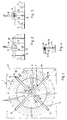
- an air outlet 1 is shown in plan view, which is commonly known commercially as DQJ.
- This air outlet 1 has arranged like a dial Louvers 2 in an outlet plate 3, which in the shown Embodiment have different lengths can.
- Air louvres 4 are assigned to each louver 2 between two bearing plates 5, as in the German Utility model 93 03 875 shown, stored. In the Figures 2 to 4 are these air deflection blades and their Storage indicated.
- a truss device 6 is provided, on the one hand a cross 7 with the air outlet 1 and on the other hand a threaded bolt 8 are connected to the counter bearing can.
- a threaded bolt 8 are connected to the counter bearing can.
- the cross 7 consists of two intersecting, in cross section oval pipe sections 9 and 10, which are in the middle of the threaded bolt 8 is penetrated and held together.
- Each pipe section 8 and 9 engages with corresponding ones oval holes 11 and 12 or slot-shaped recesses 13 of holding plates 14 and 15 through, which in the Louvers 2 are used.
- This replace these holding plates 14 and 15 partially the above-mentioned bearing plates 5, so that they themselves have a bearing recess 16th for an axis 17 of the air deflection blade 4.
- a plug-in part 18 which for example consists of Plastic can be molded.
- This plug-in part 18 has a head 19 and an insert 20. In use position the head 19 strikes the holding plate from the outside 14/15, while the insert 20 in the pipe section 9 or 10 intervenes. This is an attachment without any welding or the like. possible.
- the plug 18 can instead of the plug 18 also a screw or find a pop rivet connection. This requires but again a higher effort.
- FIGS. 5 to 8 it can be seen that two embodiments of holding plates are to be used. While in the holding plate 14 according to FIGS. 5 and 6 two oval holes 11 and 12 are arranged one above the other, is located above the oval hole 11, the above slot-shaped recess 13 in which an actual oval hole is broken outwards.
- Fig. 1 The definition of the truss device 6 compared to the Air outlet 1 takes place according to Fig. 1 as follows:
- the truss device is then between the holding plate 14 6 used and the corresponding plug-in parts 18th inserted through the oval holes 11 and 12. To this The crosshead device is pre-fixed.
- the holding plate 15 are provided.
- the threaded bolt 8 into the corresponding air slots 2 used first obliquely in the louvers inserted and then rotated. Slides when turning then the pipe section 9 into the slot-shaped recess 13, the axis 17 in the bearing recess 16 and the side edges of the louver 2 in the grooves 23 and 24. This is a very simple, quick and effective attachment.
Landscapes
- Engineering & Computer Science (AREA)
- Chemical & Material Sciences (AREA)
- Combustion & Propulsion (AREA)
- Mechanical Engineering (AREA)
- General Engineering & Computer Science (AREA)
- Duct Arrangements (AREA)
- Respiratory Apparatuses And Protective Means (AREA)
- Sampling And Sample Adjustment (AREA)
- Building Environments (AREA)
Description
Claims (9)
- Luftauslaß mit Luftschlitzen (2) in einer Auslaßplatte (3), welche über eine Traverseneinrichtung (6) an einem Gegenlager festlegbar ist,
dadurch gekennzeichnet,
daß die Traverseneinrichtung (6) über Halteplättchen (14, 15) mit der Auslaßplatte (3) verbunden ist. - Luftauslaß nach Anspruch 1, dadurch gekennzeichnet, daß das Halteplättchen (14, 15) zumindest ein ovales Loch (11, 12) und/oder eine schlitzförmige Ausnehmung (13) zur Aufnahme eines im Querschnitt ovalen Rohrabschnittes (9, 10) aufweist.
- Luftauslaß nach Anspruch 2, dadurch gekennzeichnet, daß die Halteplättchen (14) zwei übereinander angeordnete ovale Löcher (11, 12) zur Aufnahmen von sich kreuzenden im Querschnitt ovalen Rorabschnitten (9, 10) aufweisen.
- Luftauslaß nach Anspruch 2, dadurch gekennzeichnet, daß ein Halteplättchen (15) über einem ovalen Loch (11) eine schlitzförmige Ausnehmung (13) aufweist.
- Luftauslaß nach einem der Ansprüche 2 - 4, dadurch gekennzeichnet, daß das Halteplättchen (14, 15) eine Lagerausnehmung (16) für eine Achse (17) einer Luftlenklamelle (4) aufweist.
- Luftauslaß nach wenigstens einem der Ansprüche 2 - 5, dadurch gekennzeichnet, daß das Halteplättchen (14, 15) durch einen abgekanteten T-Steg (21) Nuten (23, 24) zur Aufnahme von Randkanten des Luftschlitzes (2) ausbildet.
- Luftauslaß nach wenigstens einem der Ansprüche 1 - 6, dadurch gekennzeichnet, daß die Verbindung zwischen Traverseneinrichtung (6) und Halteplättchen (14, 15) über Steckteile (18) erfolgt.
- Luftauslaß nach Anspruch 7, dadurch gekennzeichnet, daß das Steckteil (18) aus einem Kopf (19) und einem Einsatz (20) besteht.
- Luftauslaß nach wenigstens einem der Ansprüche 1 - 8, dadurch gekennzeichnet, daß die Traverseneinrichtung (6) einen Gewindebolzen (8) zur Festlegung an dem Gegenlager aufweist.
Applications Claiming Priority (3)
| Application Number | Priority Date | Filing Date | Title |
|---|---|---|---|
| DE4336806A DE4336806A1 (de) | 1993-10-28 | 1993-10-28 | Luftauslaß |
| DE4336806 | 1993-10-28 | ||
| PCT/EP1994/003350 WO1995012094A1 (de) | 1993-10-28 | 1994-10-12 | Luftauslass |
Publications (2)
| Publication Number | Publication Date |
|---|---|
| EP0724699A1 EP0724699A1 (de) | 1996-08-07 |
| EP0724699B1 true EP0724699B1 (de) | 1998-01-14 |
Family
ID=6501237
Family Applications (1)
| Application Number | Title | Priority Date | Filing Date |
|---|---|---|---|
| EP94928890A Expired - Lifetime EP0724699B1 (de) | 1993-10-28 | 1994-10-12 | Luftauslass |
Country Status (7)
| Country | Link |
|---|---|
| EP (1) | EP0724699B1 (de) |
| AT (1) | ATE162292T1 (de) |
| CZ (2) | CZ95196A3 (de) |
| DE (2) | DE4336806A1 (de) |
| ES (1) | ES2111957T3 (de) |
| HU (1) | HU218694B (de) |
| WO (1) | WO1995012094A1 (de) |
Families Citing this family (2)
| Publication number | Priority date | Publication date | Assignee | Title |
|---|---|---|---|---|
| DE19611817C2 (de) * | 1996-03-26 | 2000-10-26 | Schako Metallwarenfabrik | Filterkasten |
| DE19912567B4 (de) * | 1999-03-19 | 2006-08-10 | Werner Dipl.-Ing. Wildeboer | Luftleiteinrichtung für einen Luftdurchlaß |
Family Cites Families (6)
| Publication number | Priority date | Publication date | Assignee | Title |
|---|---|---|---|---|
| US2373741A (en) * | 1942-03-13 | 1945-04-17 | William J Caldwell | Adjustable nozzle |
| JPS5818050A (ja) * | 1981-07-24 | 1983-02-02 | Hitachi Ltd | グリル取付装置 |
| DE8700243U1 (de) * | 1987-01-07 | 1987-02-26 | Schako Metallwarenfabrik Ferdinand Schad KG Zweigniederlassung Kolbingen, 7201 Kolbingen | Vorrichtung zur Be- oder Entlüftung von Räumen |
| DE8904583U1 (de) * | 1989-04-12 | 1989-07-20 | "Schako" Metallwarenfabrik Ferdinand Schad KG Zweigniederlassung Kolbingen, 7201 Kolbingen | Vorrichtung zum Auslassen von Zuluft |
| DE8911555U1 (de) * | 1989-09-28 | 1990-01-04 | "Schako" Metallwarenfabrik Ferdinand Schad KG Zweigniederlassung Kolbingen, 7201 Kolbingen | Vorrichtung zum Zuführen von kalter und/oder warmer Zuluft in einen Raum |
| DE4026932A1 (de) * | 1990-08-25 | 1992-04-30 | Schako Metallwarenfabrik | Deckenauslass |
-
1993
- 1993-10-28 DE DE4336806A patent/DE4336806A1/de not_active Withdrawn
-
1994
- 1994-10-12 WO PCT/EP1994/003350 patent/WO1995012094A1/de not_active Ceased
- 1994-10-12 ES ES94928890T patent/ES2111957T3/es not_active Expired - Lifetime
- 1994-10-12 DE DE59405049T patent/DE59405049D1/de not_active Expired - Fee Related
- 1994-10-12 CZ CZ96951A patent/CZ95196A3/cs unknown
- 1994-10-12 AT AT94928890T patent/ATE162292T1/de not_active IP Right Cessation
- 1994-10-12 CZ CZ19977073U patent/CZ6610U1/cs not_active IP Right Cessation
- 1994-10-12 EP EP94928890A patent/EP0724699B1/de not_active Expired - Lifetime
- 1994-10-12 HU HU9601104A patent/HU218694B/hu not_active IP Right Cessation
Also Published As
| Publication number | Publication date |
|---|---|
| CZ95196A3 (en) | 1996-07-17 |
| ATE162292T1 (de) | 1998-01-15 |
| HU9601104D0 (en) | 1996-06-28 |
| DE59405049D1 (de) | 1998-02-19 |
| WO1995012094A1 (de) | 1995-05-04 |
| EP0724699A1 (de) | 1996-08-07 |
| HU218694B (hu) | 2000-11-28 |
| CZ6610U1 (cs) | 1997-09-30 |
| HUT74650A (en) | 1997-01-28 |
| DE4336806A1 (de) | 1995-05-04 |
| ES2111957T3 (es) | 1998-03-16 |
Similar Documents
| Publication | Publication Date | Title |
|---|---|---|
| DE19733134A1 (de) | Anordnung zur Belüftung von elektrischen und elektronischen Geräten und Baugruppen | |
| DE2114297B2 (de) | ||
| EP0329060B1 (de) | Tragvorrichtung für eine Wand- oder Deckenverkleidung | |
| DE4227532C2 (de) | Rahmenprofil für das Rahmengestell eines Schaltschrankes | |
| DD290030A5 (de) | Wand- und/oder deckenelement | |
| DE4336806A1 (de) | Luftauslaß | |
| DE2923903A1 (de) | Wandbefestigungselement fuer plattenheizkoerper | |
| EP0472934A1 (de) | Deckenauslass | |
| AT520997B1 (de) | Montagehalter | |
| DE2622147C2 (de) | Feuerschutzeinrichtung für Luftkanäle | |
| DE2142621A1 (de) | Verbindung von rechteckprofilen | |
| DE4110281A1 (de) | Lueftungsgitter | |
| DE2525977C2 (de) | Lüftungsgitter für die Belüftung von Innenräumen | |
| EP0793025B1 (de) | Metalldübel zur Verankerung in dünnen Wandplatten | |
| DE19535466A1 (de) | Luftauslaß | |
| DE10143918B4 (de) | Schaltschrank | |
| DE2757060C3 (de) | Abluftleitvorrichtung | |
| DE3901394A1 (de) | Stossverbindung zwischen zwei flachovalen lueftungsrohrabschnitten aus blech | |
| DE19930349B4 (de) | Schlitzauslaß und Verfahren zu dessen Herstellung | |
| EP0528198B1 (de) | Lamelle zur Befestigung eines Domes an einem Lamellenraster einer Leuchte | |
| EP3803225B1 (de) | Verdrängungsluftauslass | |
| DE202023102284U1 (de) | Lüftungsgitter | |
| DE19912567A1 (de) | Luftleiteinrichtung für einen Luftdurchlaß | |
| DE2411705A1 (de) | Stochersichere luefterwand | |
| DE2524293A1 (de) | Luftkasten mit rueckschlagklappe |
Legal Events
| Date | Code | Title | Description |
|---|---|---|---|
| PUAI | Public reference made under article 153(3) epc to a published international application that has entered the european phase |
Free format text: ORIGINAL CODE: 0009012 |
|
| 17P | Request for examination filed |
Effective date: 19960420 |
|
| AK | Designated contracting states |
Kind code of ref document: A1 Designated state(s): AT CH DE ES FR IT LI NL |
|
| GRAG | Despatch of communication of intention to grant |
Free format text: ORIGINAL CODE: EPIDOS AGRA |
|
| 17Q | First examination report despatched |
Effective date: 19970211 |
|
| GRAH | Despatch of communication of intention to grant a patent |
Free format text: ORIGINAL CODE: EPIDOS IGRA |
|
| GRAH | Despatch of communication of intention to grant a patent |
Free format text: ORIGINAL CODE: EPIDOS IGRA |
|
| GRAA | (expected) grant |
Free format text: ORIGINAL CODE: 0009210 |
|
| AK | Designated contracting states |
Kind code of ref document: B1 Designated state(s): AT CH DE ES FR IT LI NL |
|
| REF | Corresponds to: |
Ref document number: 162292 Country of ref document: AT Date of ref document: 19980115 Kind code of ref document: T |
|
| REG | Reference to a national code |
Ref country code: CH Ref legal event code: NV Representative=s name: FREI PATENTANWALTSBUERO Ref country code: CH Ref legal event code: EP |
|
| REF | Corresponds to: |
Ref document number: 59405049 Country of ref document: DE Date of ref document: 19980219 |
|
| ET | Fr: translation filed | ||
| REG | Reference to a national code |
Ref country code: ES Ref legal event code: FG2A Ref document number: 2111957 Country of ref document: ES Kind code of ref document: T3 |
|
| ITF | It: translation for a ep patent filed | ||
| PLBE | No opposition filed within time limit |
Free format text: ORIGINAL CODE: 0009261 |
|
| STAA | Information on the status of an ep patent application or granted ep patent |
Free format text: STATUS: NO OPPOSITION FILED WITHIN TIME LIMIT |
|
| 26N | No opposition filed | ||
| PGFP | Annual fee paid to national office [announced via postgrant information from national office to epo] |
Ref country code: NL Payment date: 20081015 Year of fee payment: 15 |
|
| PGFP | Annual fee paid to national office [announced via postgrant information from national office to epo] |
Ref country code: CH Payment date: 20081015 Year of fee payment: 15 |
|
| PGFP | Annual fee paid to national office [announced via postgrant information from national office to epo] |
Ref country code: ES Payment date: 20081027 Year of fee payment: 15 Ref country code: AT Payment date: 20081015 Year of fee payment: 15 |
|
| PGFP | Annual fee paid to national office [announced via postgrant information from national office to epo] |
Ref country code: IT Payment date: 20081025 Year of fee payment: 15 |
|
| PGFP | Annual fee paid to national office [announced via postgrant information from national office to epo] |
Ref country code: FR Payment date: 20081014 Year of fee payment: 15 |
|
| PGFP | Annual fee paid to national office [announced via postgrant information from national office to epo] |
Ref country code: DE Payment date: 20081218 Year of fee payment: 15 |
|
| REG | Reference to a national code |
Ref country code: NL Ref legal event code: V1 Effective date: 20100501 |
|
| REG | Reference to a national code |
Ref country code: CH Ref legal event code: PL |
|
| REG | Reference to a national code |
Ref country code: FR Ref legal event code: ST Effective date: 20100630 |
|
| PG25 | Lapsed in a contracting state [announced via postgrant information from national office to epo] |
Ref country code: NL Free format text: LAPSE BECAUSE OF NON-PAYMENT OF DUE FEES Effective date: 20100501 Ref country code: FR Free format text: LAPSE BECAUSE OF NON-PAYMENT OF DUE FEES Effective date: 20091102 Ref country code: DE Free format text: LAPSE BECAUSE OF NON-PAYMENT OF DUE FEES Effective date: 20100501 |
|
| PG25 | Lapsed in a contracting state [announced via postgrant information from national office to epo] |
Ref country code: AT Free format text: LAPSE BECAUSE OF NON-PAYMENT OF DUE FEES Effective date: 20091012 |
|
| PG25 | Lapsed in a contracting state [announced via postgrant information from national office to epo] |
Ref country code: LI Free format text: LAPSE BECAUSE OF NON-PAYMENT OF DUE FEES Effective date: 20091031 Ref country code: CH Free format text: LAPSE BECAUSE OF NON-PAYMENT OF DUE FEES Effective date: 20091031 |
|
| REG | Reference to a national code |
Ref country code: ES Ref legal event code: FD2A Effective date: 20110328 |
|
| PG25 | Lapsed in a contracting state [announced via postgrant information from national office to epo] |
Ref country code: IT Free format text: LAPSE BECAUSE OF NON-PAYMENT OF DUE FEES Effective date: 20091012 |
|
| PG25 | Lapsed in a contracting state [announced via postgrant information from national office to epo] |
Ref country code: ES Free format text: LAPSE BECAUSE OF NON-PAYMENT OF DUE FEES Effective date: 20110315 |
|
| PG25 | Lapsed in a contracting state [announced via postgrant information from national office to epo] |
Ref country code: ES Free format text: LAPSE BECAUSE OF NON-PAYMENT OF DUE FEES Effective date: 20091013 |