EP0724716B1 - Integrale Lecksuche an einem Verdampfer für Kältemaschinen mit weiterer Messung - Google Patents
Integrale Lecksuche an einem Verdampfer für Kältemaschinen mit weiterer Messung Download PDFInfo
- Publication number
- EP0724716B1 EP0724716B1 EP94929552A EP94929552A EP0724716B1 EP 0724716 B1 EP0724716 B1 EP 0724716B1 EP 94929552 A EP94929552 A EP 94929552A EP 94929552 A EP94929552 A EP 94929552A EP 0724716 B1 EP0724716 B1 EP 0724716B1
- Authority
- EP
- European Patent Office
- Prior art keywords
- valve
- evaporator
- measurement
- line
- chamber
- Prior art date
- Legal status (The legal status is an assumption and is not a legal conclusion. Google has not performed a legal analysis and makes no representation as to the accuracy of the status listed.)
- Expired - Lifetime
Links
- 238000005259 measurement Methods 0.000 title claims description 30
- 238000001514 detection method Methods 0.000 title claims description 29
- 238000000034 method Methods 0.000 claims description 17
- 239000007789 gas Substances 0.000 claims description 16
- 239000001307 helium Substances 0.000 claims description 15
- 229910052734 helium Inorganic materials 0.000 claims description 15
- SWQJXJOGLNCZEY-UHFFFAOYSA-N helium atom Chemical compound [He] SWQJXJOGLNCZEY-UHFFFAOYSA-N 0.000 claims description 14
- 239000002826 coolant Substances 0.000 description 21
- 239000003507 refrigerant Substances 0.000 description 10
- 230000035945 sensitivity Effects 0.000 description 4
- 238000001816 cooling Methods 0.000 description 3
- ATUOYWHBWRKTHZ-UHFFFAOYSA-N Propane Chemical compound CCC ATUOYWHBWRKTHZ-UHFFFAOYSA-N 0.000 description 2
- 230000006835 compression Effects 0.000 description 2
- 238000007906 compression Methods 0.000 description 2
- 238000005429 filling process Methods 0.000 description 2
- 230000001133 acceleration Effects 0.000 description 1
- XAGFODPZIPBFFR-UHFFFAOYSA-N aluminium Chemical compound [Al] XAGFODPZIPBFFR-UHFFFAOYSA-N 0.000 description 1
- 229910052782 aluminium Inorganic materials 0.000 description 1
- 239000001273 butane Substances 0.000 description 1
- 238000010586 diagram Methods 0.000 description 1
- 230000007613 environmental effect Effects 0.000 description 1
- 238000001704 evaporation Methods 0.000 description 1
- 230000008020 evaporation Effects 0.000 description 1
- 238000004880 explosion Methods 0.000 description 1
- 239000003292 glue Substances 0.000 description 1
- 150000002371 helium Chemical class 0.000 description 1
- 238000004519 manufacturing process Methods 0.000 description 1
- 238000012986 modification Methods 0.000 description 1
- 230000004048 modification Effects 0.000 description 1
- IJDNQMDRQITEOD-UHFFFAOYSA-N n-butane Chemical compound CCCC IJDNQMDRQITEOD-UHFFFAOYSA-N 0.000 description 1
- OFBQJSOFQDEBGM-UHFFFAOYSA-N n-pentane Natural products CCCCC OFBQJSOFQDEBGM-UHFFFAOYSA-N 0.000 description 1
- 230000000149 penetrating effect Effects 0.000 description 1
- 239000001294 propane Substances 0.000 description 1
- 238000005086 pumping Methods 0.000 description 1
- 238000005057 refrigeration Methods 0.000 description 1
- 238000005096 rolling process Methods 0.000 description 1
- 230000002123 temporal effect Effects 0.000 description 1
- 238000009423 ventilation Methods 0.000 description 1
Images
Classifications
-
- G—PHYSICS
- G01—MEASURING; TESTING
- G01M—TESTING STATIC OR DYNAMIC BALANCE OF MACHINES OR STRUCTURES; TESTING OF STRUCTURES OR APPARATUS, NOT OTHERWISE PROVIDED FOR
- G01M3/00—Investigating fluid-tightness of structures
- G01M3/02—Investigating fluid-tightness of structures by using fluid or vacuum
- G01M3/04—Investigating fluid-tightness of structures by using fluid or vacuum by detecting the presence of fluid at the leakage point
- G01M3/20—Investigating fluid-tightness of structures by using fluid or vacuum by detecting the presence of fluid at the leakage point using special tracer materials, e.g. dye, fluorescent material, radioactive material
- G01M3/22—Investigating fluid-tightness of structures by using fluid or vacuum by detecting the presence of fluid at the leakage point using special tracer materials, e.g. dye, fluorescent material, radioactive material for pipes, cables or tubes; for pipe joints or seals; for valves; for welds; for containers, e.g. radiators
- G01M3/226—Investigating fluid-tightness of structures by using fluid or vacuum by detecting the presence of fluid at the leakage point using special tracer materials, e.g. dye, fluorescent material, radioactive material for pipes, cables or tubes; for pipe joints or seals; for valves; for welds; for containers, e.g. radiators for containers, e.g. radiators
- G01M3/228—Investigating fluid-tightness of structures by using fluid or vacuum by detecting the presence of fluid at the leakage point using special tracer materials, e.g. dye, fluorescent material, radioactive material for pipes, cables or tubes; for pipe joints or seals; for valves; for welds; for containers, e.g. radiators for containers, e.g. radiators for radiators
-
- G—PHYSICS
- G01—MEASURING; TESTING
- G01M—TESTING STATIC OR DYNAMIC BALANCE OF MACHINES OR STRUCTURES; TESTING OF STRUCTURES OR APPARATUS, NOT OTHERWISE PROVIDED FOR
- G01M3/00—Investigating fluid-tightness of structures
- G01M3/02—Investigating fluid-tightness of structures by using fluid or vacuum
- G01M3/04—Investigating fluid-tightness of structures by using fluid or vacuum by detecting the presence of fluid at the leakage point
- G01M3/20—Investigating fluid-tightness of structures by using fluid or vacuum by detecting the presence of fluid at the leakage point using special tracer materials, e.g. dye, fluorescent material, radioactive material
- G01M3/202—Investigating fluid-tightness of structures by using fluid or vacuum by detecting the presence of fluid at the leakage point using special tracer materials, e.g. dye, fluorescent material, radioactive material using mass spectrometer detection systems
Definitions
- An evaporator is part of the coolant circuit the condensed coolant flows through a nozzle. An evaporation and cooling process takes place. The evaporator cools down and is therefore able to extract heat from its surroundings (cooling capacity).
- the Coolant circuit of a compression refrigerator can have one or more evaporators arranged in parallel.
- Household refrigerators are usually plate evaporators used. These consist of two e.g. by Glue or tightly connected by rolling Sheets, preferably made of aluminum.
- the channel through which the coolant vapor flows Embossed curvature In at least one of the Plate is the channel through which the coolant vapor flows Embossed curvature.
- the inlet nozzle is also a component of the plate evaporator. For example, it will made that the coolant channel in the inlet area with a pincer-like tool is narrowed.
- the lifespan of chillers, especially refrigerators depends largely on the tightness of the refrigerant circuit from. It is therefore known the refrigerant cycle a chiller based on the principle of sniffing leak detection to check for leaks. With the help of a so-called Sniffers become suspect areas by hand scanned. Gases are constantly sucked in through the sniffer and one set to a specific test gas Test gas detector supplied. The sensitivity of sniffing leak detection is limited. In addition, this is done by hand performed leak detection procedures the risk that through human error is a suspect area either not scanned at all or overlooked a leak there becomes. After all, this type of leak detection is time consuming.
- the aim of the present invention is further properties of test specimens with a cavity to investigate.
- evaporators for refrigeration machines that are properties that are essential for the efficiency of the chiller are crucial.
- a property of this kind is for example the ratio between the volume of the Refrigerant circuit and in the refrigerant circuit amount of refrigerant.
- That mentioned Relationship also scatters because Average volume of the refrigerant circuit assumed and the refrigerant charge always remains the same. Also have the properties of the inlet nozzle Influence on the efficiency of the chiller.
- the invention is therefore based on the object in addition to the tightness of the specimen, other properties to be able to recognize and measure.
- the invention is based on the knowledge that only one minor modification to that for integral leak detection required technical means is necessary to make accurate Knowledge of the other properties mentioned To receive the examinee. Knowing this data can, for example the refrigerant charge for measurements on evaporators can be individually adapted to each evaporator, so that optimal efficiencies can be achieved.
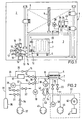
- the evaporator 7 in the chamber 3 Before carrying out the measurements, the evaporator 7 in the chamber 3 inserted and fixed (fixing blocks 4).
- the Inlet opening 9 of the evaporator 7 is connected to the high pressure connection 13, the outlet opening 12 with the low pressure connection 14 connected.
- the chamber 3 with the help of Chamber lid 5 closed vacuum-tight.
- the postponement the chamber cover 5 takes place with the help of the pneumatic cylinder 6.
- the chamber 3 and the means for moving the lid 5 are mounted on a work surface 2. Above the Working area 2 are operating and display devices. Valves, vacuum pumps, measuring tubes and the like are located below the work surface 2.
- the flow meter 17 and the valve 15 is a bypass line 36 assigned in which the valve 16 is located. This is opened immediately before the flow measurement and closed again immediately. This ensures that the pressure generated by the compressed air source 35 at the beginning the flow measurement is in full in front of the nozzle 11. For the immediately following flow measurement a measuring time of a few seconds is then sufficient.
- the volume measurement is then carried out only the valve 18 is closed. This takes place in Cavity of the test specimen 7 or in the refrigerant channel 8 Pressure build up instead. With the help of the pressure gauge 19 is this pressure build-up registered. It has been shown that extremely precise volume measurements are already being carried out can if the time measurements are made in a pressure range in which the pressure build-up in the coolant channel 8 is practically still linear.
- the volume of the Coolant channel 8 is proportional to the measured time. Out the measured time and that in the previous measurement the value supplied by the flow meter 17 allows the volume of the Determine coolant channel 8 in test specimen 7 exactly.
- Another method is measuring the pressure increase on the basis that takes place in the coolant channel 8, also in a pressure range in which the temporal Pressure increase is practically still linear.
- the steeper the Pressure rise curve the smaller the volume of the Coolant channel 8. From the flow meter 17 during the Flow measurement delivered value and the pressure increase the volume of the coolant channel 8 can be calculated.
- Valve 15 To fill the coolant channel 8 with helium Valve 15 closed and those in line 32 Valves 18 and 34 open. This makes the test port 14 and thus the outlet opening of the test specimen 7 with the vacuum pump 37 connected.
- the device under test 7 is expediently placed on a Pressure evacuated in the lower area of the rough vacuum lies.
- Valve 31 supplies a helium source (e.g. with 8 bar) to the line 32 connected. This helium flows into the coolant channel 8 a so that the leak detection can be started. With the help of the pressure gauge 26, these processes controlled.
- valve 38 With valve 38 open are inlet opening 9 and outlet opening 12 of the test specimen 7 in the evacuation phase with the vacuum pump 37 and in the Helium filling phase connected to the helium source. In addition to the Acceleration of the evacuation and filling process furthermore achieved that in the coolant channel 8 still residual gases are removed more thoroughly.
- the Chamber 3 evacuated using the vacuum pump 41.
- the valve 43 which is used for evacuation the chamber 3 is opened.
- the valve 43 is closed. The pressure control takes place with the aid of the pressure measuring device 28.
- the valve 43 is bypassed with the throttle valve 24 assigned. This enables the evacuation process after closing the valve 43 with reduced pumping power to continue. This way you can achieve a higher one Sensitivity.
- the leak detector 27 is switched on with the aid of the valve 25.
- the leak detector 27 comprises the backing pump 45, the high vacuum pump (turbomolecular vacuum pump) 46 and the mass spectrometer 47.
- the required operating pressure approx. 10 -4 mbar.
- the operating pressure is checked with the aid of the vacuum measuring instrument 48.
- Helium which may flow through a leak in the test specimen 7, reaches the mass spectrometer 47 (contra-flow principle) against the delivery direction of the high-vacuum pump 46 and is registered there.
- the helium located in the evaporator 7 is released via the expansion valve 33.
- the chamber 3 is flooded via the valve 23.
- the chamber 3 can then be opened for the purpose of changing the test piece 7.
- Figure 1 shows that the chamber 3 below the table surface 2nd equipped with an additional chamber 51 arranged on the side is.
- This chamber 51 is used for leak detection Components (valves 23, 24, 25, 43, pressure gauge 28) connected.
- the advantages of this solution are that the clear height of the chamber 3 itself and thus its volume small can be held. It also avoids that reduced Intake cross sections must be used and that Gas flows that occur during the evacuation and ventilation of the chamber 3 occur, exert forces on the test object.
Landscapes
- Physics & Mathematics (AREA)
- General Physics & Mathematics (AREA)
- Examining Or Testing Airtightness (AREA)
Description
- Figur 1
- eine Draufsicht auf eine für die Durchführung des erfindungsgemäßen Verfahrens geeignete Einrichtung und
- Figur 2
- ein Schaltschema für eine Einrichtung zur Durchführung des Untersuchungsverfahrens.
- Messung des Durchflusses durch die Düse 11
- Messung des Volumens des Kühlkanals 8
- Lecktest.
Claims (18)
- Verfahren zur integralen Lecksuche an einem Verdampfer (7) für Kältemaschinen mit Hilfe einer für die Durchführung dieses Verfahrens geeigneten Einrichtung, wobei diese Einrichtung eine der Aufnahme des Verdampfers (7) dienende, vakuumdicht verschließbare Kammer (3) umfasst, die mit Prüflingsanschlüssen (13, 14) ausgerüstet ist, welche der Herstellung der Verbindung von Messeinrichtungen mit einer Eintrittsöffnung (9) sowie einer Austrittsöffnung (12) des Hohlraumes (8) des Verdampfers (7) dienen, dadurch gekennzeichnet, dass nach dem Einsetzen des Verdampfers (7) in die Kammer (3) neben der integralen Lecksuche mindestens eine weitere Messung durchgeführt wird, und zwar eine Messung des Durchflusses durch den Hohlraum (8) und/oder eine Messung des Volumens des Hohlraumes (8) des Verdampfers (7).
- Verfahren nach Anspruch 1, dadurch gekennzeichnet, dass zunächst eine Durchflussmessung und danach die Leckuntersuchung durchgeführt werden.
- Verfahren nach Anspruch 1, dadurch gekennzeichnet, dass zunächst eine Volumenmessung und danach die Leckuntersuchung durchgeführt werden.
- Verfahren nach Anspruch 1, 2 oder 3, dadurch gekennzeichnet, dass nacheinander die DurchflussmesSung, die Volumenmessung und die Leckuntersuchung durchgeführt werden.
- Verfahren nach einem der Ansprüche 1 bis 4, dadurch gekennzeichnet, dass zur Volumenmessung im Prüfling (7) eine Druckerhöhung erzeugt wird und dass der Berechnung des Volumens die Steilheit der Druckanstiegskurve zugrundegelegt wird, und zwar in einem Bereich, in dem der Druckanstieg praktisch noch linear ist.
- Verfahren nach einem der vorhergehenden Ansprüche, dadurch gekennzeichnet, dass zur Durchführung der Lecksuche Helium als Testgas und ein nach dem Contra-flow-Prinzip arbeitender Leckdetektor (27) eingesetzt werden.
- Einrichtung zur Durchführung eines Verfahrens zur integralen Lecksuche an einem Verdampfer (7) für Kältemaschinen mit Hilfe einer für die Durchführung dieses Verfahrens geeigneten Einrichtung, wobei diese Einrichtung eine der Aufnahme des Verdampfers (7) dienende, vakuumdicht verschließbare Kammer (3) umfasst, die mit Prüflingsanschlüssen (13, 14) ausgerüstet ist, welche der Herstellung der Verbindung von Messeinrichtungen mit einer Eintrittsöffnung (9) sowie einer Austrittsöffnung (12) des Hohlraumes (8) des Verdampfers (7) dienen, und wobei nach dem Einsetzen des Verdampfers (7) in die Kammer (3) neben der integralen Lecksuche mindestens eine weitere Messung durchgeführt wird, und zwar eine Messung des Durchflusses durch den Hohlraum (8) und/oder eine Messung des Volumens des Hohlraumes (8), dadurch gekennzeichnet, dass der Prüflingsanschluss (13) über eine Leitung (31) mit einer Druckgasquelle (35) in Verbindung steht und dass sich in der Leitung (31) ein Flowmeter (17) und ein Ventil (15) befinden.
- Vorrichtung nach Anspruch 7, dadurch gekennzeichnet, dass dem Flowmeter (17) und dem Ventil (15) eine Bypassleitung (36) mit einem Ventil (16) zugeordnet ist.
- Vorrichtung nach einem der Ansprüche 7 oder 8, dadurch gekennzeichnet, dass der Prüflingsanschluss (14) über eine Leitung (32) mit Ventilen (18, 34) an eine Vakuumpumpe (37) anschließbar ist.
- Vorrichtung nach Anspruch 9, dadurch gekennzeichnet, dass in die Leitung (32) zwischen den Ventilen (18 und 34) Anschlußleitungen mit einem Entspannungsventil (33), einem Helium-Versorgungsventil (21) und einem Flutventil (22) münden.
- Vorrichtung nach Anspruch 9 oder 10, dadurch gekennzeichnet, dass an die Leitung (32) zwischen den Ventilen (18 und 34) ein Druckmessgerät (26) angeschlossen ist.
- Vorrichtung nach einem der Ansprüche 9, 10 oder 11, dadurch gekennzeichnet, dass an die Leitung (32) zwischen dem Prüflingsanschluss (14) und dem Ventil (18) ein Druckmessgerät (19) angeschlossen ist.
- Vorrichtung nach einem der Ansprüche 7 bis 12, dadurch gekennzeichnet, dass der zwischen dem Prüflingsanschluss (13) und dem Ventil (15) gelegene Abschnitt der Leiktung (31) mit dem zwischen dem Prüfungsanschluss (14) und dem Ventil (18) gelegenen Abschnitt der Leitung (32) über das Ventil (38) miteinander verbindbar sind.
- Vorrichtung nach einem der Ansprüche 7 bis 13, dadurch gekennzeichnet, dass an die Vakuumkammer (3) über eine Leitung (42) eine Vakuumpumpe (41) angeschlossen ist, und dass sich in der Leitung (42) zwei parallel geschaltete Ventile (24, 43) befinden, von denen das Ventil (24) als Drosselventil ausgebildet ist.
- Vorrichtung nach einem der Ansprüche 7 bis 14, dadurch gekennzeichnet, dass an die Kammer (3) über ein Ventil (25) ein Leckdetektor (27) angeschlossen ist, der ein Massenspektrometer (47) und eine im Gegenstrom vom Testgas durchströmte Hochvakuumpumpe (46) umfasst.
- Vorrichtung nach einem der Ansprüche 7 bis 15, dadurch gekennzeichnet, dass die Kammer (3) mit einer seitlich angeordneten Zusatzkammer (51) ausgerüstet ist, an die die zur Lecksuche notwendigen Mittel angeschlossen sind.
- Vorrichtung nach einem der Ansprüche 7 bis 16, dadurch gekennzeichnet, dass die Prüflingsanschlüsse (13, 14) mit zwischenevakuierten Doppeldichtungen ausgerüstet sind.
- Vorrichtung nach einem der Ansprüche 7 bis 17, dadurch gekennzeichnet, dass sie eine Arbeitsfläche (2) aufweist, dass sich oberhalb der Arbeitsfläche (2) Bedienungs- und Anzeigegeräte befinden und dass sich unterhalb der Arbeitsfläche (2) Ventile, Messröhren, Vakuumpumpen usw. befinden.
Applications Claiming Priority (3)
| Application Number | Priority Date | Filing Date | Title |
|---|---|---|---|
| DE4335894A DE4335894A1 (de) | 1993-10-21 | 1993-10-21 | Verfahren zur Untersuchung der Eigenschaften eines Prüflings mit einem Hohlraum sowie für die Durchführung dieses Verfahrens geeignete Einrichtung |
| DE4335894 | 1993-10-21 | ||
| PCT/EP1994/003405 WO1995011434A1 (de) | 1993-10-21 | 1994-10-15 | Verfahren zur untersuchung der eigenschaften eines prüflings mit einem hohlraum sowie für die durchführung dieses verfahrens geeignete einrichtung |
Publications (2)
| Publication Number | Publication Date |
|---|---|
| EP0724716A1 EP0724716A1 (de) | 1996-08-07 |
| EP0724716B1 true EP0724716B1 (de) | 1999-08-04 |
Family
ID=6500656
Family Applications (1)
| Application Number | Title | Priority Date | Filing Date |
|---|---|---|---|
| EP94929552A Expired - Lifetime EP0724716B1 (de) | 1993-10-21 | 1994-10-15 | Integrale Lecksuche an einem Verdampfer für Kältemaschinen mit weiterer Messung |
Country Status (3)
| Country | Link |
|---|---|
| EP (1) | EP0724716B1 (de) |
| DE (2) | DE4335894A1 (de) |
| WO (1) | WO1995011434A1 (de) |
Families Citing this family (7)
| Publication number | Priority date | Publication date | Assignee | Title |
|---|---|---|---|---|
| DE10354301B3 (de) * | 2003-11-20 | 2005-08-18 | Eaton Fluid Power Gmbh | Vakuummessbehälter |
| FR3068781A1 (fr) | 2017-07-06 | 2019-01-11 | Ateq | Procede de detection de fuite d'une piece creuse et installation pour la mise en œuvre d'un tel procede |
| CN109211485B (zh) * | 2017-07-06 | 2022-07-26 | 亚得克 | 检测中空零件泄露的方法和实施该方法的装置 |
| FR3073623B1 (fr) | 2017-11-16 | 2019-11-08 | Ateq | Installation et procede de detection et de localisation de fuite dans un circuit de transport d'un fluide, notamment d'un aeronef |
| FR3092171B1 (fr) | 2019-01-29 | 2021-04-30 | Ateq | Système de détection de fuite par gaz traceur et utilisation correspondante. |
| DE102020207524B3 (de) | 2020-06-18 | 2021-09-30 | Carl Zeiss Smt Gmbh | Verfahren zum Prüfen der Dichtigkeit mindestens eines Kanals |
| DE102020119600A1 (de) * | 2020-07-24 | 2022-01-27 | Inficon Gmbh | Vakuumlecksuchsystem, Gassteuereinheit und Verfahren zur Gaslecksuche |
Family Cites Families (11)
| Publication number | Priority date | Publication date | Assignee | Title |
|---|---|---|---|---|
| DE2009197A1 (en) * | 1970-02-27 | 1971-09-09 | Volkswagenwerk Ag | Gas leak testing device |
| SU1247663A1 (ru) * | 1984-12-19 | 1986-07-30 | Предприятие П/Я М-5612 | Способ определени объема емкости |
| SU1364938A1 (ru) * | 1986-05-29 | 1988-01-07 | Предприятие П/Я В-2739 | Способ определени локальной негерметичности полых изделий |
| SU1430772A1 (ru) * | 1987-03-26 | 1988-10-15 | Предприятие П/Я В-2190 | Способ испытани на герметичность изделий |
| DE3815308A1 (de) * | 1988-05-05 | 1989-11-16 | Rolf Pohlmann | Verfahren zum pruefen der dichtigkeit von gasrohrleitungen insbesondere in wohnhaeusern und geraetesatz zur durchfuehrung dieses verfahrens |
| US4899573A (en) * | 1989-02-24 | 1990-02-13 | American Glass Research, Inc. | Apparatus and an associated method for leak and volume inspection of containers |
| DE4008687A1 (de) * | 1990-03-17 | 1991-09-19 | Schuetz Werke Gmbh Co Kg | Pruefverfahren fuer sicherheitsbehaelter |
| DE4017853C2 (de) * | 1990-06-02 | 1993-12-23 | Martin Lehmann | Anschluß zum Befüllen eines Behältnisses und Vorrichtung zum Prüfen des Volumens von Behältnissen |
| FR2666654B1 (fr) * | 1990-09-12 | 1994-12-23 | Cit Alcatel | Dispositif de controle d'etancheite d'une piece. |
| DE4107787A1 (de) * | 1991-03-11 | 1992-09-17 | Pierburg Gmbh | Vorrichtung zum messen des anteils fluessigen brennstoffs in einem tank |
| DE4214958C2 (de) * | 1992-05-11 | 1994-06-09 | Kronseder Maschf Krones | Kontinuierlich arbeitende Inspektionsmaschine für Gefäße |
-
1993
- 1993-10-21 DE DE4335894A patent/DE4335894A1/de not_active Withdrawn
-
1994
- 1994-10-15 WO PCT/EP1994/003405 patent/WO1995011434A1/de not_active Ceased
- 1994-10-15 EP EP94929552A patent/EP0724716B1/de not_active Expired - Lifetime
- 1994-10-15 DE DE59408594T patent/DE59408594D1/de not_active Expired - Fee Related
Also Published As
| Publication number | Publication date |
|---|---|
| DE59408594D1 (de) | 1999-09-09 |
| WO1995011434A1 (de) | 1995-04-27 |
| DE4335894A1 (de) | 1995-04-27 |
| EP0724716A1 (de) | 1996-08-07 |
Similar Documents
| Publication | Publication Date | Title |
|---|---|---|
| EP0285864B1 (de) | Verfahren und Vorrichtung zur Leckprüfung an mit Flüssigkeiten gefüllten Systemen | |
| DE102011086486B4 (de) | Vorrichtung und Verfahren zur schnellen Lecksuche an formsteifen/schlaffen Verpackungen ohne Zusatz von Prüfgas | |
| EP0283543B1 (de) | Lecksuchgerät und Betriebsverfahren dazu | |
| EP2008073A2 (de) | Verfahren und vorrichtung zur bestimmung der dichtigkeit eines prüfobjekts | |
| EP2601498B1 (de) | Lecksuchgerät | |
| EP0805962A1 (de) | Testgas-lecksuchgerät | |
| DE69422551T2 (de) | Verfahren zum Einfüllen eines nichtazeotropen Kältemittels in einen Kältekreislauf und zum Einstellen dessen Zusammensetzung | |
| EP3894821B1 (de) | Dichtheitsprüfung eines flüssigkeitsgefüllten prüflings | |
| DE1648648B2 (de) | Anordnung zur Lecksuche nach dem Massenspektrometer Prinzip | |
| DE19627922A1 (de) | Verfahren und Vorrichtung zur Rückgewinnung des bei der Heliumlecksuche verwendeten Heliums | |
| WO2017084974A1 (de) | Lecksuche mit sauerstoff | |
| DE4335894A1 (de) | Verfahren zur Untersuchung der Eigenschaften eines Prüflings mit einem Hohlraum sowie für die Durchführung dieses Verfahrens geeignete Einrichtung | |
| DE10156205A1 (de) | Testgaslecksuchgerät | |
| EP0927345B1 (de) | Verfahren zur untersuchung einer mehrzahl ähnlicher prüflinge auf lecks | |
| DE2403360A1 (de) | Leckpruefverfahren | |
| DE10254120B3 (de) | Verfahren zur Dichtheitsprüfung von Klimaanlagen in Kraftfahrzeugen | |
| DE102006052551A1 (de) | Leckageprüfung bei einer Klimaanlage | |
| DE9320396U1 (de) | Einrichtung zur Untersuchung von Eigenschaften eines Prüflings mit einem Hohlraum | |
| DE102006039925B4 (de) | Verfahren zur Bestimmung des Kältemittelverlusts von Kälteanlagen | |
| DE19737869A1 (de) | Verfahren und Vorrichtung zur Dichtigkeitsprüfung | |
| DE4102179A1 (de) | Verfahren und anordnung zum betreiben einer kaeltemaschine | |
| DD288207A5 (de) | Einrichtung zum gasdichten absperren der druckleitung einer kompressionskaelteanlage | |
| DE3426677A1 (de) | Verfahren zur leckpruefung eines bauteils | |
| DE3332814A1 (de) | Dichtheitspruefgeraet zur lokalisierung von undichtigkeiten an hohlkoerpern | |
| DE2301262A1 (de) | Verfahren und vorrichtung zur leckpruefung von roehren und dergleichen teilen |
Legal Events
| Date | Code | Title | Description |
|---|---|---|---|
| PUAI | Public reference made under article 153(3) epc to a published international application that has entered the european phase |
Free format text: ORIGINAL CODE: 0009012 |
|
| 17P | Request for examination filed |
Effective date: 19960229 |
|
| AK | Designated contracting states |
Kind code of ref document: A1 Designated state(s): CH DE FR GB IT LI |
|
| RAP1 | Party data changed (applicant data changed or rights of an application transferred) |
Owner name: BALZERS UND LEYBOLD DEUTSCHLAND HOLDING AKTIENGESE |
|
| 17Q | First examination report despatched |
Effective date: 19970507 |
|
| GRAG | Despatch of communication of intention to grant |
Free format text: ORIGINAL CODE: EPIDOS AGRA |
|
| GRAG | Despatch of communication of intention to grant |
Free format text: ORIGINAL CODE: EPIDOS AGRA |
|
| GRAH | Despatch of communication of intention to grant a patent |
Free format text: ORIGINAL CODE: EPIDOS IGRA |
|
| GRAH | Despatch of communication of intention to grant a patent |
Free format text: ORIGINAL CODE: EPIDOS IGRA |
|
| GRAA | (expected) grant |
Free format text: ORIGINAL CODE: 0009210 |
|
| AK | Designated contracting states |
Kind code of ref document: B1 Designated state(s): CH DE FR GB IT LI |
|
| PG25 | Lapsed in a contracting state [announced via postgrant information from national office to epo] |
Ref country code: IT Free format text: LAPSE BECAUSE OF FAILURE TO SUBMIT A TRANSLATION OF THE DESCRIPTION OR TO PAY THE FEE WITHIN THE PRE;WARNING: LAPSES OF ITALIAN PATENTS WITH EFFECTIVE DATE BEFORE 2007 MAY HAVE OCCURRED AT ANY TIME BEFORE 2007. THE CORRECT EFFECTIVE DATE MAY BE DIFFERENT FROM THE ONE RECORDED.SCRIBED TIME-LIMIT Effective date: 19990804 Ref country code: GB Free format text: LAPSE BECAUSE OF FAILURE TO SUBMIT A TRANSLATION OF THE DESCRIPTION OR TO PAY THE FEE WITHIN THE PRESCRIBED TIME-LIMIT Effective date: 19990804 Ref country code: FR Free format text: LAPSE BECAUSE OF FAILURE TO SUBMIT A TRANSLATION OF THE DESCRIPTION OR TO PAY THE FEE WITHIN THE PRESCRIBED TIME-LIMIT Effective date: 19990804 |
|
| REG | Reference to a national code |
Ref country code: CH Ref legal event code: EP |
|
| REF | Corresponds to: |
Ref document number: 59408594 Country of ref document: DE Date of ref document: 19990909 |
|
| PG25 | Lapsed in a contracting state [announced via postgrant information from national office to epo] |
Ref country code: LI Free format text: LAPSE BECAUSE OF NON-PAYMENT OF DUE FEES Effective date: 19991031 Ref country code: CH Free format text: LAPSE BECAUSE OF NON-PAYMENT OF DUE FEES Effective date: 19991031 |
|
| EN | Fr: translation not filed | ||
| GBV | Gb: ep patent (uk) treated as always having been void in accordance with gb section 77(7)/1977 [no translation filed] |
Effective date: 19990804 |
|
| PLBE | No opposition filed within time limit |
Free format text: ORIGINAL CODE: 0009261 |
|
| STAA | Information on the status of an ep patent application or granted ep patent |
Free format text: STATUS: NO OPPOSITION FILED WITHIN TIME LIMIT |
|
| REG | Reference to a national code |
Ref country code: CH Ref legal event code: PL |
|
| 26N | No opposition filed | ||
| PGFP | Annual fee paid to national office [announced via postgrant information from national office to epo] |
Ref country code: DE Payment date: 20040917 Year of fee payment: 11 |
|
| PG25 | Lapsed in a contracting state [announced via postgrant information from national office to epo] |
Ref country code: DE Free format text: LAPSE BECAUSE OF NON-PAYMENT OF DUE FEES Effective date: 20060503 |