EP0724738B1 - Article a triedres trirectangle asymetriques et son procede de fabrication - Google Patents
Article a triedres trirectangle asymetriques et son procede de fabrication Download PDFInfo
- Publication number
- EP0724738B1 EP0724738B1 EP95901011A EP95901011A EP0724738B1 EP 0724738 B1 EP0724738 B1 EP 0724738B1 EP 95901011 A EP95901011 A EP 95901011A EP 95901011 A EP95901011 A EP 95901011A EP 0724738 B1 EP0724738 B1 EP 0724738B1
- Authority
- EP
- European Patent Office
- Prior art keywords
- cube corner
- groove
- article
- grooves
- substrate
- Prior art date
- Legal status (The legal status is an assumption and is not a legal conclusion. Google has not performed a legal analysis and makes no representation as to the accuracy of the status listed.)
- Expired - Lifetime
Links
- 238000004519 manufacturing process Methods 0.000 title claims description 33
- 238000000034 method Methods 0.000 title claims description 29
- 239000000758 substrate Substances 0.000 claims description 70
- 238000003754 machining Methods 0.000 claims description 25
- 239000002131 composite material Substances 0.000 claims description 17
- 238000007789 sealing Methods 0.000 claims description 5
- 239000012780 transparent material Substances 0.000 claims description 3
- 238000003491 array Methods 0.000 description 50
- 230000003287 optical effect Effects 0.000 description 47
- 239000000463 material Substances 0.000 description 20
- 238000000926 separation method Methods 0.000 description 15
- 238000005520 cutting process Methods 0.000 description 10
- 230000015572 biosynthetic process Effects 0.000 description 9
- 230000008901 benefit Effects 0.000 description 8
- 229910052751 metal Inorganic materials 0.000 description 4
- 239000002184 metal Substances 0.000 description 4
- 230000004048 modification Effects 0.000 description 4
- 238000012986 modification Methods 0.000 description 4
- 239000004417 polycarbonate Substances 0.000 description 4
- 229920000515 polycarbonate Polymers 0.000 description 4
- 229920006397 acrylic thermoplastic Polymers 0.000 description 3
- 230000004888 barrier function Effects 0.000 description 3
- 230000000694 effects Effects 0.000 description 3
- 238000005516 engineering process Methods 0.000 description 3
- 150000002739 metals Chemical class 0.000 description 3
- 229920003229 poly(methyl methacrylate) Polymers 0.000 description 3
- ISXSCDLOGDJUNJ-UHFFFAOYSA-N tert-butyl prop-2-enoate Chemical compound CC(C)(C)OC(=O)C=C ISXSCDLOGDJUNJ-UHFFFAOYSA-N 0.000 description 3
- PXHVJJICTQNCMI-UHFFFAOYSA-N Nickel Chemical compound [Ni] PXHVJJICTQNCMI-UHFFFAOYSA-N 0.000 description 2
- 230000009286 beneficial effect Effects 0.000 description 2
- 230000005540 biological transmission Effects 0.000 description 2
- 230000015556 catabolic process Effects 0.000 description 2
- 238000000576 coating method Methods 0.000 description 2
- 238000010276 construction Methods 0.000 description 2
- 230000001747 exhibiting effect Effects 0.000 description 2
- -1 ferrous metals Chemical class 0.000 description 2
- 239000004033 plastic Substances 0.000 description 2
- 229920003023 plastic Polymers 0.000 description 2
- 238000007493 shaping process Methods 0.000 description 2
- QNRATNLHPGXHMA-XZHTYLCXSA-N (r)-(6-ethoxyquinolin-4-yl)-[(2s,4s,5r)-5-ethyl-1-azabicyclo[2.2.2]octan-2-yl]methanol;hydrochloride Chemical compound Cl.C([C@H]([C@H](C1)CC)C2)CN1[C@@H]2[C@H](O)C1=CC=NC2=CC=C(OCC)C=C21 QNRATNLHPGXHMA-XZHTYLCXSA-N 0.000 description 1
- 229910001369 Brass Inorganic materials 0.000 description 1
- RYGMFSIKBFXOCR-UHFFFAOYSA-N Copper Chemical compound [Cu] RYGMFSIKBFXOCR-UHFFFAOYSA-N 0.000 description 1
- 241001465754 Metazoa Species 0.000 description 1
- 229920005372 Plexiglas® Polymers 0.000 description 1
- 239000004698 Polyethylene Substances 0.000 description 1
- 229920003182 Surlyn® Polymers 0.000 description 1
- 239000012963 UV stabilizer Substances 0.000 description 1
- 239000000654 additive Substances 0.000 description 1
- 230000002411 adverse Effects 0.000 description 1
- 230000004075 alteration Effects 0.000 description 1
- 229910052782 aluminium Inorganic materials 0.000 description 1
- XAGFODPZIPBFFR-UHFFFAOYSA-N aluminium Chemical compound [Al] XAGFODPZIPBFFR-UHFFFAOYSA-N 0.000 description 1
- 239000010951 brass Substances 0.000 description 1
- 229920006217 cellulose acetate butyrate Polymers 0.000 description 1
- 239000003086 colorant Substances 0.000 description 1
- 238000010924 continuous production Methods 0.000 description 1
- 229910052802 copper Inorganic materials 0.000 description 1
- 239000010949 copper Substances 0.000 description 1
- 230000000593 degrading effect Effects 0.000 description 1
- 230000001419 dependent effect Effects 0.000 description 1
- 238000009795 derivation Methods 0.000 description 1
- 229910003460 diamond Inorganic materials 0.000 description 1
- 239000010432 diamond Substances 0.000 description 1
- 239000000975 dye Substances 0.000 description 1
- 239000011521 glass Substances 0.000 description 1
- 238000000227 grinding Methods 0.000 description 1
- 238000010348 incorporation Methods 0.000 description 1
- 238000001746 injection moulding Methods 0.000 description 1
- 229920000554 ionomer Polymers 0.000 description 1
- 238000003801 milling Methods 0.000 description 1
- 229910052759 nickel Inorganic materials 0.000 description 1
- 239000000049 pigment Substances 0.000 description 1
- 229920000728 polyester Polymers 0.000 description 1
- 229920000573 polyethylene Polymers 0.000 description 1
- 239000004926 polymethyl methacrylate Substances 0.000 description 1
- 229920002635 polyurethane Polymers 0.000 description 1
- 239000004814 polyurethane Substances 0.000 description 1
- 230000008569 process Effects 0.000 description 1
- 238000004886 process control Methods 0.000 description 1
- 230000009467 reduction Effects 0.000 description 1
- 239000011347 resin Substances 0.000 description 1
- 229920005989 resin Polymers 0.000 description 1
- 229920001169 thermoplastic Polymers 0.000 description 1
- 229920001187 thermosetting polymer Polymers 0.000 description 1
- 239000004416 thermosoftening plastic Substances 0.000 description 1
- 238000007514 turning Methods 0.000 description 1
Images




Classifications
-
- G—PHYSICS
- G02—OPTICS
- G02B—OPTICAL ELEMENTS, SYSTEMS OR APPARATUS
- G02B5/00—Optical elements other than lenses
- G02B5/12—Reflex reflectors
- G02B5/122—Reflex reflectors cube corner, trihedral or triple reflector type
- G02B5/124—Reflex reflectors cube corner, trihedral or triple reflector type plural reflecting elements forming part of a unitary plate or sheet
-
- Y—GENERAL TAGGING OF NEW TECHNOLOGICAL DEVELOPMENTS; GENERAL TAGGING OF CROSS-SECTIONAL TECHNOLOGIES SPANNING OVER SEVERAL SECTIONS OF THE IPC; TECHNICAL SUBJECTS COVERED BY FORMER USPC CROSS-REFERENCE ART COLLECTIONS [XRACs] AND DIGESTS
- Y10—TECHNICAL SUBJECTS COVERED BY FORMER USPC
- Y10T—TECHNICAL SUBJECTS COVERED BY FORMER US CLASSIFICATION
- Y10T29/00—Metal working
- Y10T29/49—Method of mechanical manufacture
- Y10T29/49995—Shaping one-piece blank by removing material
- Y10T29/49996—Successive distinct removal operations
-
- Y—GENERAL TAGGING OF NEW TECHNOLOGICAL DEVELOPMENTS; GENERAL TAGGING OF CROSS-SECTIONAL TECHNOLOGIES SPANNING OVER SEVERAL SECTIONS OF THE IPC; TECHNICAL SUBJECTS COVERED BY FORMER USPC CROSS-REFERENCE ART COLLECTIONS [XRACs] AND DIGESTS
- Y10—TECHNICAL SUBJECTS COVERED BY FORMER USPC
- Y10T—TECHNICAL SUBJECTS COVERED BY FORMER US CLASSIFICATION
- Y10T409/00—Gear cutting, milling, or planing
- Y10T409/30—Milling
- Y10T409/303752—Process
Definitions
- This invention relates to retroreflective articles having prismatic retroreflective elements.
- Retroreflective elements including prismatic designs incorporating one or more raised structures commonly known as cube corners. Retroreflective sheeting which employs cube corner type reflecting elements is well known. Cube corner reflecting elements are trihedral structures which have three approximately mutually perpendicular lateral faces meeting in a single corner. Light rays are typically reflected at the cube faces due to either total internal reflection or reflective coatings.
- the manufacture of directly machined arrays comprising retroreflective cube corner elements has many inefficiencies and limitations. Total light return and percent active aperture are adversely affected by these limitations, and overall production costs versus performance are often higher relative to the new class of articles and methods of manufacture taught below.
- the asymmetric arrays of this invention permit excellent manufacturing flexibility and production of cube corner element designs which are highly tailorable to particular needs.
- the invention comprises a method of manufacturing a retroreflective cube corner article comprising the steps of providing a machinable substrate material suitable for forming reflective surfaces, and creating a plurality of geometric structures including cube corner elements in the substrate.
- the step of creating the cube corner elements comprises directly machining at least three sets of parallel grooves in the substrate so that only one side of at least one groove in at least one groove set forms cube corner element optical surfaces.
- the invention also includes retroreflective replicas of an article manufactured according to this method.
- the invention also includes a method of manufacturing an article having a plurality of geometric structures including cube corner elements formed by directly machining three sets of parallel grooves into a machinable substrate.
- a first groove set of parallel grooves is directly machined along a first path in the substrate.
- a second groove set of parallel grooves is directly machined along a second path in the substrate.
- a third groove set comprising at least one additional groove is directly machined along a third path in the substrate. Only one side of at least one groove in at least one groove set forms cube corner element optical surfaces.
- the invention also comprises a retroreflective cube corner article which is a replica of a machined substrate in which a plurality of geometric structures including cube corner elements are directly machined.
- Each cube corner element is bounded by a groove from each of three sets of parallel grooves. Only one side of at least one groove in at least one groove set forms cube corner element optical surfaces.
- the article exhibits asymmetric entrance angularity when rotated about an axis within the plane of the substrate.
- the invention also comprises a retroreflective article which is a replica of a directly machined substrate having a plurality of geometric structures including directly machined canted cube corner elements.
- the cube corner elements are arranged between a plurality of grooves in the substrate which intersect at angles of other than 90°.
- Each cube corner element has a symmetry axis, and the symmetry axis of substantially every one of the cube corner elements in the article is in substantially parallel relation to each other.
- the invention also comprises a retroreflective cube corner element composite sheeting comprising a plurality of zones of retroreflective cube corner elements in an ordered array within each zone.
- the array of each zone comprises a replica of a directly machined substrate in which a plurality of cube corner elements are machined in the substrate.
- Each cube corner element is bounded by a groove from each of three sets of parallel grooves in the substrate, and only one side of at least one groove in at least one groove set forms cube corner element optical surfaces.
- the invention also comprises a retroreflective cube corner element composite sheeting comprising a plurality of zones of retroreflective cube corner elements in an ordered array within each zone.
- the array of each zone comprises a replica of a directly machined substrate in which a plurality of cube corner elements are machined in the substrate between a plurality of grooves which intersect at angles of other than 90°.
- Each cube corner element has a symmetry axis, and the symmetry axis of substantially every one of the cube corner elements within each zone is in substantially parallel relation to each other.
- molds made by different techniques including those known as pin bundling and direct machining. Molds manufactured using pin bundling are made by assembling together individual pins which each have an end portion shaped with features of a cube-corner retroreflective element.
- U.S. Patent No. 3,926,402 (Heenan et al) and U.S. Patent No. 3,632,695 (Howell) are examples of pin bundling.
- the direct machining technique also known generally as ruling, comprises cutting portions of a substrate to create a pattern of grooves which intersect to form cube corner elements.
- the grooved substrate is referred to as a master from which a series of impressions, i.e. replicas, may be formed.
- the master is useful as a retroreflective article, however replicas, including multi-generational replicas, are more commonly used as the retroreflective article.
- Direct machining is an excellent method for manufacturing master molds for small micro-cube arrays. Small micro-cube arrays are particularly beneficial for producing thin replica arrays with improved flexibility, such as continuous rolled goods for sheeting purposes. Micro-cube arrays are also more conducive to continuous process manufacturing. The process of manufacturing large arrays is also relatively easier using direct machining methods rather than other techniques.
- One example of direct machining is shown in U.S. Patent No. 4,588,258 (Hoopman).
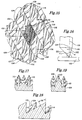
- Figure 1 illustrates a method by which directly machined masters of conventional cube arrays are manufactured.
- a directly machinable substrate 20 receives a plurality of parallel grooves 23, arranged in two non-parallel sets. Grooves through directly machinable substrate 20 are formed by a machine tool with two opposing cutting surfaces for cutting cube corner optical faces. Examples of shaping, ruling, and milling techniques suitable for forming directly machined grooves are discussed in U.S. Patent No. 3,712,706 (Stamm).
- the two groove sets 23 produce the partial cube shapes 39 depicted in the sectional views of Figure 2 and Figure 3.
- Machine tool 26, such as that shown in Figure 4 is typically mounted on a post 35 and has a cutting surface 29 on each side of a tool central axis 32.
- partial cube shapes 39 are shown as rhombus shaped structures formed in substrate 20. At least two grooves 23 in both non-parallel groove sets are required to produce shapes 39. A third groove 41, as shown in sectional view dashed lines in Figure 5, is required to produce conventional cube corner elements. Portions of a conventional cube array 42 after completion of the three groove sets are shown in Figures 6 and 7. Both sides of all grooves 23, 41 form cube corner element optical surfaces in array 42. An equilateral triangle is formed at the base of each cube corner reflecting element 44, 45. The grooves 23 and 41 mutually intersect at representative locations 43. Another example of this grooving is shown in US. Patent No. 3,712,706 (Stamm). U.S. Patent Nos.
- German patent reference DE 42 42 264 (Gubela) in which a structure is formed having a micro-double triad and two single traids within a rhombic body.
- the structure is formed in a work piece using turning angles of 60 degrees and grinding directions which do not cross each other at one point, resulting in only two of the directions having a common point of intersection.
- cube corner element retroreflective arrays comprise non-canted cubes which have individual symmetry axes 46, 47 that are perpendicular to a base plane 48, as shown in Figure 7.
- the symmetry axis is a central or optical axis which is a trisector of the internal or dihedral angles defined by the faces of the element.
- the resulting canted cube-corner elements combine to produce an array which retroreflects over a wide range of entrance angles. This is taught in U.S. Patent No.
- Hoopman 4,588,258
- the Hoopman structure is manufactured with three sets of parallel V-shaped grooves 49, 50, 51 that intersect to form matched pairs of canted cube corner elements 53, 54 in array 55. Both sides of all grooves 49, 50, 51 form cube corner element optical surfaces in array 55.
- Figure 9 illustrates the symmetry axis 57 for cube corner element 53, and the symmetry axis 58 for cube corner element 54.
- the symmetry axes are each tilted at angle ⁇ with respect to a line 60 that lies normal to a base plane 63, or the front surface, of the element.
- the base plane is usually co-planar or parallel with the front surface of a sheeting comprising the cube corner element array.
- Cube corner elements 53, 54 are geometrically congruent, exhibit symmetric optical retroreflective performance with respect to entrance angle when rotated about an axis within the plane of the substrate, and have symmetry axes which are not parallel to each other. Entrance angle is commonly defined as the angle formed between the light ray entering the front surface and line 60.
- Canting may be in either a forward or backward direction.
- the Hoopman patent includes disclosure of a structure having an amount of cant up to 13° for a refractive index of 1.5.
- Hoopman also discloses a cube with a cant of 9.736°.
- This geometry represents the maximum forward cant of cubes in a conventional array before the grooving tool damages cube optical surfaces. The damage normally occurs during formation of a third groove when the tool removes edge portions of adjacent elements. For example, as shown in Figure 8, for forward cants beyond 9.736°, the cube edge 65 is formed by the first two grooves 49, 50 and is removed by forming the primary groove 51.
- U.S. Patent No. 2,310,790 discloses a structure which is canted in a direction opposite that shown in the Hoopman patent.
- optical performance is conveniently defined by the percent of the surface area that is actually retroreflective, i.e. which comprises an effective area or active aperture.
- the percent active aperture varies as a function of the amount of canting, refractive index, and the entrance angle.
- shaded areas 68 of Figure 10 represent the active apertures of the individual cube corner retroreflective elements in array 42.
- the active apertures shown in Figure 10 are a uniform hexagonal size and shape.
- the percent active aperture of this equilateral 60°-60°-60° base angle geometry array at a zero entrance angle is about 67 percent, which is the maximum possible for a conventional three groove set array.
- Conventional cube corner retroreflective element designs include structural and optical limitations which are overcome by use of the asymmetric cube corner retroreflective element structures and methods of manufacture described below.
- Use of this new class of asymmetric retroreflective cube corner element structures and manufacturing methods permits diverse cube corner element shaping. For example, cubes in a single array may be readily manufactured with raised discontinuous geometric structures having different heights and non-vertical optical surfaces. Non-vertical cube surfaces are more easily metalized, processed, and replicated.
- Use of asymmetric methods and structures also permits manufacture of cubes which have highly tailorable asymmetric optical performance. For example, at many entrance angles, including at zero entrance angle, asymmetric structures outperform conventional structures by exhibiting higher percent active apertures or by providing improved divergence profiles, or both.
- Asymmetric manufacturing techniques also produce enhanced optical performance resulting from closely spaced intermixed cubes with different active aperture shapes and sizes. This presents more uniform appearances of asymmetric arrays over a wide range of viewing distances under both day and night observation conditions.
- Such advantages of asymmetric cube corner elements enhance the usefulness of articles having these elements.
- Such articles include, for example, traffic control materials, retroreflective vehicle markings, photoelectric sensors, directional reflectors, and reflective garments for human or animal use.
- Asymmetric cubes are not derived from the simple matching of pairs of cubes or from a modification of conventional pairs of cubes. Therefore, asymmetric arrays permit placement of optically active cubes in the areas which, if conventional, would not be optically active.
- Asymmetric cube corner element arrays may be of simple or composite construction. Manufacture of asymmetric cube corner element master arrays, as well as multi-generational replicas, results in diverse and highly adaptable optical performance and cost efficiencies. These and other advantages are described more fully below.
- a substrate suitable for forming retroreflective surfaces according to this invention may comprise any material suitable for forming directly machined grooves or groove sets. Suitable materials should machine cleanly without burr formation, exhibit low ductility and low graininess, and maintain dimensional accuracy after groove formation.
- a variety of materials such as machinable plastics or metals may be utilized. Suitable plastics comprise thermoplastic or thermoset materials such as acrylics or other materials. Suitable metals include aluminum, brass, nickel, and copper. Preferred metals include non-ferrous metals. Preferred machining materials should also minimize wear of the cutting tool during formation of the grooves.
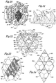
- Figure 15 discloses a method by which directly machined masters of asymmetric cube corner element arrays are manufactured.
- a directly machined substrate 100 receives a plurality of parallel grooves arranged in two non-parallel sets, which may have variable spacing between grooves. Grooves may be formed using either single or multiple passes of a machine tool through substrate 100.
- Each groove is preferably formed by a machine tool which has only one side configured for cutting a retroreflective non-vertical optical surface and which is maintained in an approximately constant orientation relative to the substrate during the formation of each groove.
- Each groove forms the side surfaces of geometric structures which may include cube corner optical or non-optical elements.
- a more detailed description of a method of manufacturing an asymmetric cube corner element array is to directly machine a first groove set 104 of parallel grooves 106 cut into substrate 100 along a first path.
- a second groove set 107 of parallel grooves 108 is then directly machined along a second path in substrate 100.
- the machining of the first and second groove sets also referred to as the two secondary grooves or secondary groove sets, creates a plurality of rhombus or diamond shaped partial cube sub-elements 109, depicted in shaded highlight in one instance for ease of recognition.
- Each partial cube sub-element comprises two orthogonal optical faces 110, as shown in Figures 15, 17 and 19.
- grooves 106 and 108 form the orthogonal faces 110 on partial cube sub-element 109.
- the secondary grooves intersect at locations 114.
- Asymmetric arrays may be compared to conventional arrays at this point of manufacture by comparing analogous views of Figures 1 and 15, 2 and 19, 3 and 17, and 5 and 18.
- a third or primary groove set which may contain as few as one groove, is cut along a third path in substrate 100.
- a representative primary groove 116 which in this example mutually intersects the secondary grooves 106 and 108, is shown in dotted lines. A more detailed discussion of such primary groove(s) is found below in relation to groove set 128 and groove(s) 130 depicted in the array embodiment of Figure 20.
- Each of the secondary grooves 106, 108 are preferably formed using a novel half angle tool 118, shown in one embodiment in Figure 16.
- the half angle tool 118 is typically mounted on a post 119 with a post axis 124.
- Half angle tool 118 comprises a cutting surface 120 for cutting retroreflective optical surfaces into substrate 100, and a relief surface 122.
- Relief surface 122 may actually cut substrate 100, but it will preferably not cut or shape optical surfaces which provide retroreflection.
- the relief angle X may be any angle, although a preferred range of angles is between 0° and 30°. In Figures 15, and 17-23 relief angle X is 0°.
- the tool side angle Y shown in Figure 16 is non-zero and preferably specified to create orthogonal or nearly orthogonal cube optical surfaces. This provides a preferred machine tool which has only one side configured for cutting an optical surface of a cube corner element.
- the half angle tool 118 is typically mounted offset on the post axis 124 with tool side angle x not equal to relief angle y.
- the tool axis is set perpendicular to the substrate during direct machining.
- the half angle tool 118 may be mounted centered on the post axis 124.
- Tool side angle x will equal relief angle y in this case, and the tool axis 124 is tilted relative to the substrate during direct machining.
- Intermediate combinations of offset tool mounting and tilting of the post during direct machining may also be beneficially utilized to produce the desired groove side and relief angles in the substrate.
- groove side angle for secondary grooves 106, 108 is the same. However, different groove side angles may be used provided corresponding variations in relative secondary groove orientation are utilized to maintain orthogonal or nearly orthogonal partial cube sub-element surfaces.
- a third or primary groove set 128, which may contain as few as one groove 130, is preferably cut using a pass along a third path in substrate 100.
- the addition of a plurality of parallel primary grooves 130 is shown in Figures 20 and 21.
- Third groove set 128 is cut through partial cube sub-elements so that non-canted individual cube corner elements 134, 135, 136, with cube peaks 137, 138, 139 are formed by the intersections of the primary groove(s) with the orthogonal faces of the partial cube sub-elements.
- Primary grooves 130 may intersect the secondary grooves either individually or at the locations of the secondary groove intersections.
- Another embodiment of this method of manufacturing asymmetric cube corner elements is to directly machine three non-parallel sets of grooves into substrate 100 in any order using at least one machine tool configured similarly to half angle tool 118.
- the invention also comprises a retroreflective cube corner article which is a replica of a directly machined substrate in which a plurality of geometric structures including cube corner elements are machined in the substrate.
- each cube corner element is bounded by at least one groove from each of three sets of parallel grooves in the substrate. Only one side of at least one groove in at least one groove set forms cube corner element optical surfaces.
- grooves or groove sets in a method of forming cube corner elements according to this invention may comprise a different scope and meaning from grooves or groove sets which bound or form a cube corner element in known articles. For example, in known articles, multiple passes of a machine tool may be required to form a single groove.
- inventions of this method include creation of an article, or replicas of the article, which further modify the shape of the retroreflected light pattern.
- These embodiments comprise at least one groove side angle in at least one set of grooves which differs from the angle necessary to produce an orthogonal intersection with other faces of elements defined by the groove sides.
- at least one set of grooves may comprise a repeating pattern of at least two groove side angles that differ from one another.
- Shapes of grooving tools, or other techniques may create cube corner elements in which at least a significant portion of at least one cube corner element optical face on at least some of the cubes is arcuate. The arcuate face may be concave or convex.
- the arcuate face which was initially formed by one of the grooves in one of the groove sets, is flat in a direction parallel to said groove.
- the arcuate face may be cylindrical, with the axis of the cylinder parallel to said groove, or may have a varying radius of curvature in a direction perpendicular to said groove.
- Figure 20 further discloses asymmetric cube array 141 in which primary grooves 130 do not pass through the secondary grooves 106, 108 at the mutual intersection locations 114 of the secondary grooves.
- Primary grooves 130 are equally spaced and centered on secondary groove intersection locations 114.
- Array 141 presents yet another novel feature of asymmetric cube corner technology.
- a method is disclosed for manufacturing a cube corner article by directly machining three non-parallel non-mutually intersecting sets of grooves. Preferably, these sets intersect at included angles less than 90°. It is recognized that certain machining imprecisions may create minor, unintentional separation between grooves at intersections. However, this invention involves intentional and substantial separation.
- a separation distance between the intersections of the grooves within two groove sets with at least one groove in a third groove set which is greater than about 0.01 millimeters would likely provide the advantages of this feature.
- the precise minimum separation distance is dependent on the specific tooling, substrate, process controls, and the desired optical performance sought.
- Non-mutually intersecting groove sets create individual cube corner elements with different active aperture sizes and shapes. Arrays may even be formed with cube corners created by a combination of mutually and non-mutually intersecting groove sets.
- the position of the groove sets is controlled to produce maximum total light return over a desired range of entrance angles.
- the distance between grooves in at least one groove set might not be equal to the distance between grooves in at least another of the groove sets.
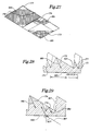
- Figures 21 and 22 illustrate the multiple cube surfaces which are formed during direct machining of a groove in substrate 100.
- Groove 108 is formed by machining surfaces 147 on numerous cube corner elements.
- Groove 106 is formed by machining surfaces 150, and groove 130 is formed by the machining of surfaces 153.
- Figures 20-22 show how the tool(s) used with the methods of this invention form more than one optical surface simultaneously.
- Figure 21 shows that the plurality of optical surfaces and cube peaks 137, 138, 139 are created at different heights above a common reference plane 154.
- Asymmetric cube corner element arrays are preferably formed using at least three sets of parallel grooves where only one side of at least one groove in at least one of the groove sets forms cube corner element optical surfaces.
- Figure 23 is a plan view of a portion of asymmetric retroreflective cube corner element array 141 depicted in Figure 22 with shaded areas 155, 156, 157 representing three different active apertures, intermixed and arranged in close proximity and corresponding to cube types 134, 135, and 136.
- a non-canted asymmetric cube corner element array similar to that shown in Figures 22 and 23 may have a percent active aperture greater than 70 percent and possibly as high as about 92 percent at 0° entrance angle.
- Figures 15 and 17-23 disclose arrays manufactured with a half angle tool 118 with a relief angle X equal to zero.
- the tool axis 124 was set perpendicular to the substrate during direct machining.
- a non-zero relief angle X was used to machine array 158 in Figure 24 and to produce non-vertical non-reflective relief surfaces 160.
- This relief angle selection flexibility provided by asymmetric array manufacturing methods permits controllable selection of percent active aperture loss due to increased relief angles.
- non-vertical relief surfaces 160 are quite helpful during the manufacture and mechanical separation of replicas since interlocking vertical faces are eliminated.
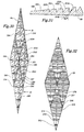
- Figures 26 and 27 illustrate an asymmetric array 165 with the symmetry axis canted forward by 21.78°. This amount of forward canting is beyond the 9.736° limit associated with conventional cube arrays.
- Each of the primary grooves 167 has a 4° relief angle, and each of the secondary grooves 169, 170 has a 20° relief angle.
- the secondary groove intersection locations 171 are designed with a spacing distance D 1 .
- Primary grooves 167 are equally spaced, also with the distance D 1 , and are positioned at .155D 1 from each adjacent intersection location 171. This pattern is repeated in other partial cube sub-elements.
- Trihedron 177 is an example of a structure formed by asymmetric cube corner element technology which is not retroreflective because the three faces are not orthogonal.
- Figure 27 shows the multiple differently sized and shaped active apertures 184, 185, 186, intermixed and arranged in close proximity, and corresponding to the three cube types numbered 172, 173, and 174 at a 60° entrance angle and a refractive index of 1.59.
- Total percent active aperture for array 165 is roughly 59 percent under these conditions. This design is useful in applications requiring high brightness at high entrance angles, for example, in pavement markers, roadway dividers, barriers, and similar uses.
- Figures 28 and 29 are side section views of canted asymmetric array 165.
- Figure 28 shows cube 172 with a symmetry axis 188.
- Figure 29 shows cubes 173, 174 with symmetry axes 189, 190 respectively.
- the shape of each of the retroreflective cubes 172, 173, 174 differs, the symmetry axes 188, 189, 190 are essentially parallel.
- Figure 29 illustrates the ray path of a light ray 187 entering array 165 at a 60° entrance angle.
- Another embodiment of this invention comprises an article that is constructed from a machinable substrate which has a plurality of directly machined geometric structures including retroreflective cube corner elements arranged between a plurality of grooves in the substrate. Each of the grooves intersects other grooves at included angles other than 90°, and each cube corner element has a symmetry axis which is in substantially parallel relation to the other symmetry axes.
- each cube corner element is preferably within a range of angles between about backward 35° and forward 54°.
- Retroreflective replicas, including multi-generational replicas, of this article may be made which have the same inventive features as the master article machined from the substrate, and it is recognized that all of the replicas are within the scope of this invention as well as the master article.
- Figures 30 and 31 disclose, in plan and sectional views, asymmetric cube corner element array 191.
- Array 191 comprises a plurality of cube corner elements each formed from primary and secondary grooves intersecting with included angles 82°, 82°, and 16°.
- Primary grooves are equally spaced through array 191, with some of the primary grooves mutually intersecting the secondary grooves at locations 194.
- the primary grooves 195 have a 30° relief angle
- the secondary grooves 196, 197 have a 3° relief angle.
- array 191 With light ray 208 entering array 191 at a 60° entrance angle and a refractive index of 1.59, the array demonstrates an exceptional 63 percent active aperture as schematically shown in Figure 32.
- This percent active aperture represents the combined optical performance of multiple differently sized and shaped apertures 212, 213, 214, 215, 216, 217, and 218, intermixed and arranged in close proximity, and corresponding to the different types of retroreflective cube corner elements 198, 199, 200, 201, 202, 203, and 204.
- Array 191 is also useful in applications requiring high brightness at high entrance angles such as pavement or channel markers, roadway dividers, barriers, and similar uses.
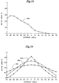
- FIG. 33 is a representative graph depicting percent active area/aperture 228 versus entrance angle for an asymmetric retroreflective cube corner element array shown in Figure 26 with a refractive index of 1.59.
- the asymmetrical optical performance based on entrance angle provides efficiencies and other advantages not previously possible in the field of retroreflective cube corner element design and use. Therefore, another embodiment of this invention comprises a retroreflective article or replica which exhibits asymmetric entrance angularity when rotated about an axis within the plane of the substrate from which it is machined.
- the article is manufactured by directly machining a substrate to create cube corner elements between three non-parallel sets of parallel grooves.
- Figure 34 provides further illustration of the asymmetric optical performance of this class of articles.
- the optical performance is represented by percent active area/aperture data lines versus entrance angle, and is shown for both conventional and asymmetric designs for a refractive index of 1.59.
- Data line 232 depicts the performance of a conventional 55°-55°-70° geometry array as shown in Figure 8; and line 235 depicts a conventional non-canted 60°-60°-60° geometry array as shown in Figure 6.
- line 244 depicts a non-canted asymmetric array as shown in Figure 24.
- a comparison between conventional geometry data lines 232, 235 and asymmetric geometry data line 244 demonstrates that higher active aperture percents are achievable with an asymmetric structure.
- the asymmetric array well exceeds the limits of conventional array percent active apertures at entrance angles up to about 25°.
- This asymmetric geometry is particularly beneficial for use in applications requiring retroreflective sheeting having substantial total light return, such as traffic control materials, retroreflective vehicle markings, photo-electric sensors, internally illuminated signs, and reflective garments.
- the enhanced optical performance and design flexibility resulting from asymmetric techniques relates directly to improved product performance and marketing advantage.
- Total light return for retroreflective sheeting is derived from the product of percent active aperture and retroreflected light ray intensity. For some combinations of cube geometries, entrance angles, and refractive index, significant reductions in ray intensity may result in relatively poor total light return even though percent active aperture is relatively high.
- retroreflective cube corner element arrays which rely on total internal reflection of the retroreflected light rays. Ray intensity is substantially reduced if the critical angle for total internal reflection is exceeded at one of the cube faces.
- Metallized or other reflective coatings on a portion of an array may be utilized advantageously in such situations. A portion, in this context, may comprise all or part of an array.
- Asymmetric cube corner element arrays relying on total internal reflection is such that total internal reflection breakdown will occur for all cubes simultaneously. This contrasts with conventional arrays, based on matched pairs of cubes, where total internal reflection breakdown occurs for only half of the cubes for a given cube geometry, entrance angle, and refractive index.
- Asymmetric cube corner element arrays relying on total internal reflection may therefore be beneficially designed as directional retroreflectors for applications such as marine channel markers and passive airport runway markings.
- Composite tiling is the technique for combining zones of cube corner elements having different orientations. This is used with conventional arrays to provide sheeting with a uniform appearance at high angles of incidence regardless of orientation. However, composite tiling permits further modification to optical performance of asymmetric arrays, as well as to arrays comprising non-triangular based cube corner prisms.
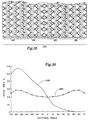
- composite array 252 comprises several zones of asymmetric arrays 165, as shown in Figure 26.
- Each of the zones 165 may have a similar size and shape, but each zone is oriented in a 180° relation to adjacent zones.
- Figure 36 shows the effect of this particular composite tiling arrangement on percent active aperture.
- Data line 228 represents the percent active aperture versus entrance angle for array 165.
- data line 260 illustrates a substantially constant value for percent active aperture versus entrance angle for composite array 252 over an extremely wide range of entrance angles.
- the combined optical effect of numerous zones 165 in a composite array is useful for applications requiring roughly constant brightness over a wide range of entrance angles.
- Data line 260 also illustrates that composite tiled zones of asymmetric cube corner elements can provide symmetric entrance angularity during rotation about an axis within the plane of the composite array.
- the zones of asymmetric arrays may be different sizes and may also be oriented other than 180° relative to adjacent zones.
- the size of the zones should be selected according to the requirements of particular applications. For example, traffic control applications may require zones which are sufficiently small that they are not visually resolvable by the unaided human eye at the minimum expected viewing distance. This provides a composite array with a uniform appearance.
- channel marking or directional reflector applications may require zones which are sufficiently large that they can be easily resolved by the unaided human eye at maximum required viewing distance.
- Figure 37 is a side section view of one embodiment of the present invention. This view shows part of an asymmetric array 264 which is similar to array 141 shown in Figure 21, although this embodiment of the invention may also be used with other array configurations. Figure 37 further illustrates the advantages of asymmetric manufacturing methods in providing geometric structures at different heights above a common reference plane. These structures may comprise individual retroreflective cube corner elements 268, 269, non-retroreflective pyramids, frustums, posts 282, or other structures positioned above common reference plane 274.
- Cube peaks 271, 272, or other features machined from the original substrate may also be truncated for specialized effect or use. Truncation may be accomplished by various techniques, including, for example, controlling depth of cut of the grooves, or further removal of substrate material after formation of the primary and secondary grooves.
- Retroreflective directly machined cube corner articles are often designed to receive a sealing film which is applied to the retroreflective article in order to maintain a low refractive index material, such as air, next to the retroreflective elements for improved performance.
- this medium is often placed in direct contact with the cube corner elements in ways which degrade total light return.
- a sealing medium 280 may be placed on the highest surface 283 of the array without contacting and degrading the optical properties of lower retroreflective cube corner elements.
- the highest surface may comprise cube corner elements, non-retroreflective pyramids, frustums, posts, or other structures. In Figure 37, the highest surface 283 has been truncated.
- the truncated surfaces may be used both to hold the medium above the cube corner elements as well as to increase the light transmissivity of the sheeting. Light transmissivity of the sheeting may be increased through use of a transparent or partially transparent sealing medium.
- Figure 38 is a side view of another embodiment of the present invention. This view shows part of an asymmetric array 285 similar to a portion of array 264 in Figure 37 but including the use of a separation surface 288.
- the lateral faces 292, 293 of geometric structures 295, 296 form the boundary edges 299, 300 for the separation surface.
- the lateral faces may be either cube corner element optical surfaces or relief surfaces.
- the separation surface 288 may have flat or curved portions when taken in cross section.
- Separation surfaces may be advantageously utilized to increase light transmission or transparency in sheeting, including flexible sheeting, utilizing asymmetric retroreflective cube corner element arrays. For example, this is particularly useful in articles such as automotive signal light reflectors, which are normally manufactured using injection molding.
- separation surfaces are shown in combination with truncated surfaces of highest surfaces 283, although either feature may be utilized independently.
- Separation surface 288 may be formed using a machining tool with a flat or curved tip, or by further removal of material from a replica of the asymmetric cube corner element array master.
- Suitable materials for retroreflective articles or sheeting of this invention are preferably transparent materials which are dimensionally stable, durable, weatherable, and easily replicated into the desired configuration.
- suitable materials include glass; acrylics, which have an index of refraction of about 1.5, such as Plexiglas brand resin manufactured by Rohm and Haas Company; polycarbonates, which have an index of refraction of about 1.59; reactive materials such as taught in United States Patents Nos. 4,576,850, 4,582,885 and 4,668,558; polyethylene based ionomers, such as those marketed under the brand name of SURLYN by E. I.
- Dupont de Nemours and Co., Inc. polyesters, polyurethanes; and cellulose acetate butyrates.
- Polycarbonates are particularly suitable because of their toughness and relatively higher refractive index, which generally contributes to improved retroreflective performance over a wider range of entrance angles.
- These materials may also include dyes, colorants, pigments, UV stabilizers, or other additives. Transparency of the materials ensures that the separation or truncated surfaces will transmit light through those portions of the article or sheeting.
- truncated or separation surfaces does not eliminate the retroreflectivity of the article, but rather it renders the entire article partially transparent. In some applications requiring partially transparent materials, low indices of refraction of the article will improve the range of light transmitted through the article. In these applications, the increased transmission range of acrylics (refractive index of about 1.5) is desirable.
- materials having high indices of refraction are preferred.
- materials such as polycarbonates, with refractive indices of about 1.59, are used to increase the difference between the indices of the material and air, thus increasing retroreflection.
- Polycarbonates are also generally preferred for their temperature stability and impact resistance.
- Figures 39 and 40 illustrate an asymmetric array 305 comprising a plurality of cube corner elements each formed from primary and secondary grooves intersecting with included angles 74°, 74°, and 32°.
- Each of the primary grooves 308 has a 30° relief angle and each of the secondary grooves 309, 310 has a 3° relief angle.
- the secondary groove intersection locations 313 are designed with a spacing D 2 .
- Three primary grooves are positioned in the partial cube sub-element with varying spacing at .20D 2 , .55D 2 , and .83D 2 from the secondary groove intersections 313. This pattern is repeated in other partial cube sub-elements.
- FIG. 39 there are six different cube types depicted by numerals 316, 317, 318, 319, 320, and 321.
- Trihedrons 325, 326 are examples of structures which are not retroreflective because the three faces are not orthogonal.
- Figure 40 shows, for entrance angle 60° and refractive index 1.59, the six active apertures 329, 330, 331, 332, 333, and 334, intermixed and arranged in close proximity, and associated with cube types numbered 316 through 321, respectively.
- Percent active aperture is roughly 63 percent for array 305.
- the active aperture shapes in this design have roughly equal dimensions both parallel and perpendicular to the primary grooves even at a 60° entrance angle.
- the asymmetric array 305 is particularly useful in applications requiring high brightness at high entrance angles, such as pavement or channel markers, roadway dividers, barriers, and similar uses.
Landscapes
- Physics & Mathematics (AREA)
- General Physics & Mathematics (AREA)
- Optics & Photonics (AREA)
- Optical Elements Other Than Lenses (AREA)
- Laminated Bodies (AREA)
Claims (23)
- Objet à trièdres trirectangles comprenant un substrat (100) ayant une surface structurée comportant une matrice de structures géométriques (134, 135, 136) formée par au moins trois ensembles de rainures se coupant (104, 107, 128), chaque structure géométrique comportant trois faces agencées selon un élément à trièdre trirectangle, caractérisé en ce qu'au moins certaines des structures géométriques (135, 136) comportent également une quatrième face qui ne fait pas partie d'un élément à trièdre trirectangle, et dans lequel au moins certaines des rainures (130) comportent :une première surface latérale s'étendant depuis le sommet de rainure formant l'une des trois faces d'élément à trièdre trirectangle ou au moins une structure géométrique (134, 135) ; etune deuxième surface latérale s'étendant depuis le sommet de rainure formant l'une des quatrièmes faces d'au moins une autre structure géométrique (135, 136).
- Objet à trièdres trirectangles selon la revendication 1, dans lequel sensiblement chaque rainure dans au moins un ensemble de rainures (128) comporte :une première surface latérale s'étendant depuis le sommet de rainure formant l'une des trois faces d'élément à trièdre trirectangle de certaines des structures géométriques ;une deuxième surface latérale s'étendant depuis le sommet de rainure formant l'une des quatrièmes faces de l'autre des structures géométriques.
- Objet à trièdres trirectangles selon la revendication 1 ou 2, dans lequel chaque rainure dans au moins un ensemble de rainures (128) comporte :une première surface latérale s'étendant depuis le sommet de rainure formant l'une des trois faces d'élément à trièdre trirectangle de certaines des structures géométriques ;une deuxième surface latérale s'étendant depuis le sommet de rainure formant l'une des quatrièmes faces de l'autre des structures géométriques.
- Objet à trièdres trirectangles selon la revendication 1, 2 ou 3, dans lequel le substrat (100) comporte un plan principal associé à celui-ci et dans lequel en outreladite première surface latérale forme un premier angle avec le plan principal et ladite deuxième surface latérale forme un deuxième angle avec ledit plan principal, ledit premier angle n'étant pas égal audit deuxième angle.
- Objet à trièdres trirectangles selon l'une quelconque des revendications 1 à 4, dans lequel chaque élément à trièdre trirectangle a un axe de symétrie et dans lequel en outreles axes de symétrie de sensiblement chaque élément à trièdre trirectangle (134, 135, 136) de ladite matrice sont inclinés dans la même direction.
- Objet à trièdres trirectangles selon l'une quelconque des revendications 1 à 5, dans lequel :une pluralité de rainures (130) à l'intérieur d'un ensemble de rainures (123) coupent les ensembles de rainures restants (104, 107) au moins à 0,01 mm de l'intersection (114) des ensembles de rainures restants (104, 107).
- Objet à trièdres trirectangles selon l'une quelconque des revendications 1 à 6, dans lequel :le sommet de rainure d'une première rainure est disposé à une première distance au-dessus d'un plan de base (154) et le sommet de rainure d'une deuxième rainure est disposé à une deuxième distance, différente de ladite première distance, au-dessus dudit plan de base (154).
- Objet à trièdres trirectangles selon l'une quelconque des revendications 1 à 7, dans lequel :la distance entre les rainures dans au moins un ensemble n'est pas égale à la distance entre les rainures dans au moins un autre des ensembles.
- Objet à trièdres trirectangles selon l'une quelconque des revendications 1 à 8, dans lequel :toutes les rainures parallèles dans l'un quelconques des ensembles ne sont pas équidistantes.
- Objet à trièdres trirectangles selon l'une quelconque des revendications 1 à 9, dans lequel :au moins une surface d'un élément à trièdre trirectangle est courbée sur une portion significative de ladite surface.
- Objet à trièdres trirectangles selon l'une quelconque des revendications 1 à 10, dans lequel :la forme de la surface courbée est sensiblement cylindrique, de façon que l'axe du cylindre soit approximativement parallèle à la rainure qui délimite ladite surface courbée.
- Objet à trièdres trirectangles selon l'une quelconque des revendications 1 à 11, dans lequel :ladite matrice est agencée pour présenter une angularité d'attaque asymétrique lorsqu'on la fait tourner autour d'un axe disposé à l'intérieur du plan principal dudit substrat (100).
- Objet à trièdres trirectangles selon l'une quelconque des revendications 1 à 12, dans lequel :ledit objet est agencé pour présenter une ouverture active supérieur à 70% en réponse à la lumière frappant une surface de base approximativement perpendiculaire à un plan de base (154), ladite surface de base étant disposée à l'opposé de ladite surface structurée.
- Objet à trièdres trirectangles selon l'une quelconque des revendications 1 à 13, dans lequel :ledit substrat (100) comprend un matériau sensiblement optiquement transparent convenable pour être utilisé dans une toile rétroréfléchissante.
- Objet à trièdres trirectangles selon l'une quelconque des revendications 1 à 14, dans lequel :une portion dudit objet est optiquement transmissive.
- Objet à trièdres trirectangles selon l'une quelconque des revendications 1 à 15, comprenant en outre :un support d'étanchéité (280) relié à une portion dudit substrat (100).
- Objet composite à trièdres trirectangles comprenant un substrat (100) ayant une surface structurée comportant :un premier objet à trièdres trirectangles selon l'une quelconque des revendications 1 à 16 et ayant une première orientation ; etun deuxième objet à trièdres trirectangles formé par au moins deux ensembles de rainures se coupant dans le substrat (100) et ayant une deuxième orientation.
- Objet à trièdres trirectangles selon la revendication 17, dans lequel :ladite orientation dudit deuxième objet à trièdres trirectangles est différente de celle dudit premier objet à trièdres trirectangles.
- Objet à trièdres trirectangles selon la revendication 17 ou 18, dans lequel :le deuxième objet à trièdres trirectangles est sélectionné de façon que ledit objet composite présente une angularité d'attaque symétrique lorsqu'on le fait tourner autour d'un axe disposé à l'intérieur du plan principal dudit substrat (100).
- Procédé de fabrication d'un objet à trièdres trirectangles comportant une matrice de structures géométriques dans lequel chaque structure géométrique comporte trois faces agencées selon un élément à trièdre trirectangle, au moins certaines des structures géométriques comportent également une quatrième face qui ne fait pas partie d'un élément à trièdre trirectangle, le procédé comprenant les étapes consistant à :fournir un substrat pouvant être usiné (100) ;usiner trois ensembles de rainures se coupant (104, 107, 128) dans ledit substrat (100) de façon queune première surface latérale s'étendant depuis le sommet de rainure d'au moins certaines des rainures (130) forme l'une des trois faces d'élément à trièdre trirectangle ou au moins une structure géométrique (134, 135) ;une deuxième surface latérale s'étendant depuis le sommet de rainure desdites au moins certaines des rainures (130) forme l'une des quatrièmes faces d'au moins une autre structure géométrique.
- Procédé selon la revendication 20, comprenant en outre l'étape consistante à :former une reproduction négative dudit objet à trièdres trirectangles.
- Procédé selon la revendication 21, comprenant en outre l'étape consistant à :former, à partir de ladite reproduction négative, une reproduction positive dudit objet à trièdres trirectangles.
- Procédé selon les revendications 20 à 22, dans lequel :des ensembles de rainures sont usinés de façon que les intersections des rainures à l'intérieur de deux ensembles de rainures ne soient pas coïncidentes avec au moins une rainure dans un troisième ensemble de rainures.
Applications Claiming Priority (3)
| Application Number | Priority Date | Filing Date | Title |
|---|---|---|---|
| US139462 | 1980-04-11 | ||
| US13946293A | 1993-10-20 | 1993-10-20 | |
| PCT/US1994/011942 WO1995011465A2 (fr) | 1993-10-20 | 1994-10-20 | Article a triedres trirectangle asymetriques et son procede de fabrication |
Publications (2)
| Publication Number | Publication Date |
|---|---|
| EP0724738A1 EP0724738A1 (fr) | 1996-08-07 |
| EP0724738B1 true EP0724738B1 (fr) | 2000-05-10 |
Family
ID=22486781
Family Applications (1)
| Application Number | Title | Priority Date | Filing Date |
|---|---|---|---|
| EP95901011A Expired - Lifetime EP0724738B1 (fr) | 1993-10-20 | 1994-10-20 | Article a triedres trirectangle asymetriques et son procede de fabrication |
Country Status (7)
| Country | Link |
|---|---|
| US (2) | US5564870A (fr) |
| EP (1) | EP0724738B1 (fr) |
| JP (1) | JP3834596B2 (fr) |
| CN (1) | CN1054918C (fr) |
| CA (1) | CA2173231A1 (fr) |
| DE (1) | DE69424436T2 (fr) |
| WO (1) | WO1995011465A2 (fr) |
Families Citing this family (57)
| Publication number | Priority date | Publication date | Assignee | Title |
|---|---|---|---|---|
| JP3590061B2 (ja) * | 1993-10-20 | 2004-11-17 | ミネソタ マイニング アンド マニュファクチャリング カンパニー | 再帰反射性コーナキューブ物品とその製作方法 |
| EP0724735B1 (fr) * | 1993-10-20 | 2002-02-20 | Minnesota Mining And Manufacturing Company | Article a triedres trirectangles retroreflechissant ayant une structure surelevee directement usinee et son procede de fabrication |
| US5600484A (en) * | 1993-10-20 | 1997-02-04 | Minnesota Mining And Manufacturing Company | Machining techniques for retroreflective cube corner article and method of manufacture |
| AU694619B2 (en) * | 1995-03-03 | 1998-07-23 | Minnesota Mining And Manufacturing Company | Light directing film having variable height structured surface and light directing article constructed therefrom |
| US5706132A (en) * | 1996-01-19 | 1998-01-06 | Minnesota Mining And Manufacturing Company | Dual orientation retroreflective sheeting |
| US6015214A (en) | 1996-05-30 | 2000-01-18 | Stimsonite Corporation | Retroreflective articles having microcubes, and tools and methods for forming microcubes |
| DE69732025T2 (de) * | 1996-10-18 | 2005-11-03 | Nippon Carbide Kogyo K.K. | Würfelecken retro-reflektorfolie mit tetraeder elementen |
| US6021559A (en) * | 1996-11-01 | 2000-02-08 | 3M Innovative Properties Company | Methods of making a cube corner article master mold |
| DE29707066U1 (de) * | 1997-04-21 | 1997-08-14 | IMOS Gubela GmbH, 77871 Renchen | Mikroretroflektor |
| US5889615A (en) * | 1997-06-27 | 1999-03-30 | Minnesota Mining And Manufacturing Company | Dual axis retroreflective articles |
| US6253442B1 (en) * | 1997-07-02 | 2001-07-03 | 3M Innovative Properties Company | Retroreflective cube corner sheeting mold and method for making the same |
| EP0993363B1 (fr) * | 1997-07-02 | 2003-08-27 | Minnesota Mining And Manufacturing Company | Revetement de triedre trirectangle retroreflechissant, moules de fabrication et procede de fabrication |
| US5981032A (en) * | 1997-07-02 | 1999-11-09 | 3M Innovative Properties Company | Retroreflective cube corner sheeting mold and sheeting formed therefrom |
| JP4235750B2 (ja) | 1997-07-02 | 2009-03-11 | スリーエム カンパニー | 再帰反射キューブコーナー製品の成形用の型に使用する薄板、この薄板を備える型組立体、及びこの型組立体から製造される再帰反射シート |
| US5898523A (en) * | 1997-07-02 | 1999-04-27 | Minnesota Mining & Manufacturing Company | Tiled retroreflective sheeting composed of highly canted cube corner elements |
| CA2303782A1 (fr) * | 1997-09-25 | 1999-04-01 | Minnesota Mining And Manufacturing Company | Article reflechissant a double usage |
| JP3580999B2 (ja) | 1997-11-17 | 2004-10-27 | 日本カーバイド工業株式会社 | 三角錐型キューブコーナー再帰反射シート |
| US6036322A (en) | 1997-12-01 | 2000-03-14 | Reflexite Corporation | Multi-orientation retroreflective structure |
| JP3975001B2 (ja) | 1998-04-22 | 2007-09-12 | 日本カーバイド工業株式会社 | 三角錐型キユーブコーナー再帰反射シート |
| US6287670B1 (en) | 1999-01-11 | 2001-09-11 | 3M Innovative Properties Company | Cube corner cavity based retroreflectors and methods for making same |
| US6540367B1 (en) * | 1999-04-07 | 2003-04-01 | 3M Innovative Properties Company | Structured surface articles containing geometric structures with compound faces and methods for making same |
| JP2001133614A (ja) * | 1999-10-29 | 2001-05-18 | Hitachi Chem Co Ltd | 拡散反射板及びその転写原型、その製造方法及びそれを用いたベースフィルム、転写フィルム、並びにこれらを用いた拡散反射板の製造方法 |
| JP3975039B2 (ja) | 1999-12-13 | 2007-09-12 | 日本カーバイド工業株式会社 | 三角錐型キューブコーナー再帰反射素子 |
| EP1271189A4 (fr) | 2000-01-31 | 2010-02-24 | Nippon Carbide Kogyo Kk | Element retroreflechissant triedre-rectangle triangulaire |
| US8728610B2 (en) * | 2000-02-25 | 2014-05-20 | 3M Innovative Properties Company | Compound mold and structured surface articles containing geometric structures with compound faces and method of making same |
| JP3468418B2 (ja) | 2000-03-15 | 2003-11-17 | 日本カーバイド工業株式会社 | 三角錐型キユーブコーナー型再帰反射シート |
| JP4028155B2 (ja) | 2000-04-11 | 2007-12-26 | 日本カーバイド工業株式会社 | 蛍光性再帰反射シート |
| US6626544B2 (en) | 2001-03-28 | 2003-09-30 | Reflexite Corporation | Prismatic retroreflector having a multi-plane facet |
| ES2332826T3 (es) * | 2001-06-19 | 2010-02-12 | Nippon Carbide Kogyo Kabushiki Kaisha | Producto retrorreflectivo que incluye un circuito integrado encerrado. |
| US6883921B2 (en) | 2001-08-09 | 2005-04-26 | Nippon Carbide Kogyo Kabushiki Kaisha | Retroreflection device |
| US6862141B2 (en) * | 2002-05-20 | 2005-03-01 | General Electric Company | Optical substrate and method of making |
| US7859759B2 (en) * | 2002-05-20 | 2010-12-28 | Sabic Innovative Plastics Ip B.V. | Film, backlight displays, and methods for making the same |
| US7180672B2 (en) * | 2002-05-20 | 2007-02-20 | General Electric Company | Optical substrate and method of making |
| US6952627B2 (en) * | 2002-12-18 | 2005-10-04 | General Electric Company | Method and apparatus for fabricating light management substrates |
| WO2005054909A1 (fr) * | 2003-12-02 | 2005-06-16 | Nippon Carbide Kogyo Kabushiki Kaisha | Article retroreflechissant sous forme de cube pyramidal triangulaire possedant une surface laterale reflechissante incurvee |
| US7072092B2 (en) * | 2003-12-31 | 2006-07-04 | General Electric Company | Optical substrate with modulated structure |
| US7195360B2 (en) * | 2004-12-28 | 2007-03-27 | 3M Innovative Properties Company | Prismatic retroreflective article and method |
| AU2005322041B2 (en) * | 2004-12-28 | 2009-10-08 | 3M Innovative Properties Company | Prismatic retroreflective article with fluorine- or silicon-containing prisms |
| US7866871B2 (en) * | 2006-01-13 | 2011-01-11 | Avery Dennison Corporation | Light enhancing structures with a plurality of arrays of elongate features |
| US7674028B2 (en) | 2006-01-13 | 2010-03-09 | Avery Dennison Corporation | Light enhancing structures with multiple arrays of elongate features of varying characteristics |
| US7366393B2 (en) * | 2006-01-13 | 2008-04-29 | Optical Research Associates | Light enhancing structures with three or more arrays of elongate features |
| US7547105B2 (en) | 2007-07-16 | 2009-06-16 | 3M Innovative Properties Company | Prismatic retroreflective article with cross-linked image layer and method of making same |
| US20090214828A1 (en) * | 2008-02-26 | 2009-08-27 | Vicki Herzl Watkins | Blunt tip prism film and methods for making the same |
| US8393229B2 (en) * | 2010-02-24 | 2013-03-12 | The Hong Kong Research Institute Of Textiles And Apparel Limited | Soft pressure sensing device |
| USD665584S1 (en) | 2010-03-05 | 2012-08-21 | Orafol Europe Gmbh | Retro-reflective sheeting with a corner cube surface pattern having angular corner cube circular regions |
| US20110216411A1 (en) * | 2010-03-05 | 2011-09-08 | David Reed | Patterned sheeting with periodic rotated patterned regions |
| US9651721B2 (en) * | 2012-08-27 | 2017-05-16 | Avery Dennison Corporation | Retroreflector with low refractive index backing |
| US20160011346A1 (en) | 2014-07-14 | 2016-01-14 | Sergiy Vasylyev | High incidence angle retroreflective sheeting |
| KR102239965B1 (ko) * | 2014-08-01 | 2021-04-15 | 미래나노텍(주) | 비대칭 피라미드 패턴을 포함하는 고휘도 광학시트 및 그 제조방법 |
| CN104133260B (zh) * | 2014-08-08 | 2016-09-14 | 浙江道明光电科技有限公司 | 一种新型的微棱镜型反光材料模具的制作方法 |
| US10925268B1 (en) * | 2015-03-13 | 2021-02-23 | Ray D. Flasco | Inside corner cubic surface reflector fishing lure |
| JP2017116779A (ja) * | 2015-12-25 | 2017-06-29 | スリーエム イノベイティブ プロパティズ カンパニー | 再帰性反射ライセンスプレート、及び再帰性反射シート |
| JP6730871B2 (ja) * | 2016-04-07 | 2020-07-29 | デクセリアルズ株式会社 | 光学体、窓材及びロールカーテン |
| CN106990460B (zh) * | 2017-04-20 | 2023-09-26 | 苏州苏大维格科技集团股份有限公司 | 微棱镜型反光膜及其制造方法 |
| US11001979B2 (en) | 2018-08-13 | 2021-05-11 | Vergence Automation, Inc. | Methods and apparatus for ultrawide entrance angle reflective articles for use with autonomous vehicle machine vision systems |
| US11762133B1 (en) | 2018-09-13 | 2023-09-19 | Vergence Automation, Inc. | Retroreflective materials and articles incorporating near-ideal total internal retroreflective elements |
| FR3112399B1 (fr) * | 2020-07-08 | 2022-06-24 | Commissariat Energie Atomique | Cible ultrasonique pour le contrôle non destructif |
Family Cites Families (56)
| Publication number | Priority date | Publication date | Assignee | Title |
|---|---|---|---|---|
| US2310790A (en) * | 1943-02-09 | Optical reflecting material | ||
| US835648A (en) * | 1906-03-13 | 1906-11-13 | Zeiss Carl Fa | Reflector. |
| US1591572A (en) * | 1925-02-05 | 1926-07-06 | Jonathan C Stimson | Process and apparatus for making central triple reflectors |
| US2027441A (en) * | 1932-11-23 | 1936-01-14 | Landis Aaron | Ornamentation for bags |
| GB423464A (en) * | 1932-12-31 | 1935-02-01 | Gustave Leray | Improvements in light reflectors |
| GB441319A (en) * | 1933-12-21 | 1936-01-16 | Gustave Leray | Improvements in or relating to light reflectors |
| GB463304A (en) * | 1934-09-20 | 1937-03-22 | Marc Aurele Marie Jacques Gall | Improvements in or relating to reflectors |
| US2407680A (en) * | 1945-03-02 | 1946-09-17 | Minnesota Mining & Mfg | Reflex light reflector |
| US3190178A (en) * | 1961-06-29 | 1965-06-22 | Minnesota Mining & Mfg | Reflex-reflecting sheeting |
| US3417959A (en) * | 1966-11-14 | 1968-12-24 | Minnesota Mining & Mfg | Die for forming retro-reflective article |
| US3924929A (en) * | 1966-11-14 | 1975-12-09 | Minnesota Mining & Mfg | Retro-reflective sheet material |
| US4208090A (en) * | 1967-03-24 | 1980-06-17 | Amerace Corporation | Reflector structure |
| US3922065A (en) * | 1968-05-31 | 1975-11-25 | Minnesota Mining & Mfg | Cube-corner retro-reflective article |
| US3632695A (en) * | 1970-03-05 | 1972-01-04 | Reflex Corp Canada Ltd | Making a combined lens and reflector |
| US3684348A (en) * | 1970-09-29 | 1972-08-15 | Rowland Dev Corp | Retroreflective material |
| US3689346A (en) * | 1970-09-29 | 1972-09-05 | Rowland Dev Corp | Method for producing retroreflective material |
| US3810804A (en) * | 1970-09-29 | 1974-05-14 | Rowland Dev Corp | Method of making retroreflective material |
| US3812706A (en) * | 1971-12-10 | 1974-05-28 | Texaco Inc | Consistometer |
| US3712706A (en) * | 1971-01-04 | 1973-01-23 | American Cyanamid Co | Retroreflective surface |
| US3811983A (en) * | 1972-06-23 | 1974-05-21 | Rowland Dev Corp | Method for producing retroreflective sheeting |
| US3873184A (en) * | 1973-02-16 | 1975-03-25 | Amerace Esna Corp | Reflector with interspersed angled reflex elements |
| US3926402A (en) * | 1973-04-24 | 1975-12-16 | Amerace Corp | Pin having nonaligned cube axis and pin axis and bundle of such pins |
| US3924928A (en) * | 1975-03-12 | 1975-12-09 | Robert C Trimble | Attachment for reflectors for spoke wheels |
| US4025159A (en) * | 1976-02-17 | 1977-05-24 | Minnesota Mining And Manufacturing Company | Cellular retroreflective sheeting |
| US4066331A (en) * | 1976-06-25 | 1978-01-03 | Beatrice Foods Co. | Cube corner type retroreflectors with improved cube corner unit relationships |
| US4349598A (en) * | 1976-12-01 | 1982-09-14 | Minnesota Mining And Manufacturing Company | High incidence angle retroreflective material |
| AU4673679A (en) * | 1979-05-07 | 1980-11-13 | Ferro Corporation | Retroreflective marking tape |
| US4149304A (en) * | 1977-09-12 | 1979-04-17 | Brynjegard Olaf G | Method of making rolls for forming radar reflective surfaces |
| US4202600A (en) * | 1978-04-24 | 1980-05-13 | Avery International Corporation | Diced retroreflective sheeting |
| US4576850A (en) * | 1978-07-20 | 1986-03-18 | Minnesota Mining And Manufacturing Company | Shaped plastic articles having replicated microstructure surfaces |
| US4668558A (en) * | 1978-07-20 | 1987-05-26 | Minnesota Mining And Manufacturing Company | Shaped plastic articles having replicated microstructure surfaces |
| US4582885A (en) * | 1978-07-20 | 1986-04-15 | Minnesota Mining And Manufacturing Company | Shaped plastic articles having replicated microstructure surfaces |
| US4243618A (en) * | 1978-10-23 | 1981-01-06 | Avery International Corporation | Method for forming retroreflective sheeting |
| US4498733A (en) * | 1982-07-02 | 1985-02-12 | Amerace Corporation | Reflector structure |
| US5156863A (en) * | 1982-09-30 | 1992-10-20 | Stimsonite Corporation | Continuous embossing belt |
| US4478769A (en) * | 1982-09-30 | 1984-10-23 | Amerace Corporation | Method for forming an embossing tool with an optically precise pattern |
| US4712867A (en) * | 1983-03-09 | 1987-12-15 | Santa Barbara Research Center | Retroreflector |
| US4588258A (en) * | 1983-09-12 | 1986-05-13 | Minnesota Mining And Manufacturing Company | Cube-corner retroreflective articles having wide angularity in multiple viewing planes |
| US4618518A (en) * | 1984-08-10 | 1986-10-21 | Amerace Corporation | Retroreflective sheeting and methods for making same |
| US4726706A (en) * | 1986-06-02 | 1988-02-23 | Attar Adil H | Reflective pavement marker |
| US4703999A (en) * | 1986-06-16 | 1987-11-03 | Minnesota Mining And Manufacturing Company | Wide-angle-reflective cube-corner retroreflective sheeting |
| US4938563A (en) * | 1986-11-21 | 1990-07-03 | Minnesota Mining And Manufacturing Company | High efficiency cube corner retroflective material |
| US4775219A (en) * | 1986-11-21 | 1988-10-04 | Minnesota Mining & Manufacturing Company | Cube-corner retroreflective articles having tailored divergence profiles |
| US4801193A (en) * | 1988-03-04 | 1989-01-31 | Reflexite Corporation | Retroreflective sheet material and method of making same |
| US4952023A (en) * | 1988-03-18 | 1990-08-28 | Minnesota Mining And Manufacturing Company | Internally illuminated retroreflective sign |
| US4895428A (en) * | 1988-07-26 | 1990-01-23 | Minnesota Mining And Manufacturing Company | High efficiency retroreflective material |
| US5183597A (en) * | 1989-02-10 | 1993-02-02 | Minnesota Mining And Manufacturing Company | Method of molding microstructure bearing composite plastic articles |
| US5175030A (en) * | 1989-02-10 | 1992-12-29 | Minnesota Mining And Manufacturing Company | Microstructure-bearing composite plastic articles and method of making |
| US5122902A (en) * | 1989-03-31 | 1992-06-16 | Minnesota Mining And Manufacturing Company | Retroreflective articles having light-transmissive surfaces |
| US5171624A (en) * | 1990-06-01 | 1992-12-15 | Reflexite Corporation | Retroreflective microprismatic material and method of making same |
| US5138488A (en) * | 1990-09-10 | 1992-08-11 | Minnesota Mining And Manufacturing Company | Retroreflective material with improved angularity |
| US5237449A (en) * | 1991-01-29 | 1993-08-17 | Nelson Optics Company, Inc. | Biased lenticular sign system |
| DE4242264C2 (de) * | 1992-12-15 | 1994-09-22 | Gubela Sen Hans Erich | Körper oder Bauteil mit einer Mikrodoppeltripel aufweisenden Oberfläche sowie Verfahren zur Herstellung eines derartigen Körpers oder Bauteils |
| DE9217179U1 (de) * | 1992-12-16 | 1993-04-22 | Gubela Sen., Hans-Erich, 77871 Renchen | Mikrodoppeltripel-Flächen |
| US5272562A (en) * | 1993-02-05 | 1993-12-21 | Minnesota Mining And Manufacturing Company | Cube-corner retroreflective articles |
| US5450235A (en) * | 1993-10-20 | 1995-09-12 | Minnesota Mining And Manufacturing Company | Flexible cube-corner retroreflective sheeting |
-
1994
- 1994-10-20 EP EP95901011A patent/EP0724738B1/fr not_active Expired - Lifetime
- 1994-10-20 WO PCT/US1994/011942 patent/WO1995011465A2/fr not_active Ceased
- 1994-10-20 US US08/326,588 patent/US5564870A/en not_active Expired - Lifetime
- 1994-10-20 DE DE69424436T patent/DE69424436T2/de not_active Expired - Fee Related
- 1994-10-20 CA CA002173231A patent/CA2173231A1/fr not_active Abandoned
- 1994-10-20 JP JP51219695A patent/JP3834596B2/ja not_active Expired - Fee Related
- 1994-10-20 CN CN94193784.4A patent/CN1054918C/zh not_active Expired - Fee Related
-
1996
- 1996-06-06 US US08/660,785 patent/US5831767A/en not_active Expired - Lifetime
Also Published As
| Publication number | Publication date |
|---|---|
| JP3834596B2 (ja) | 2006-10-18 |
| WO1995011465A2 (fr) | 1995-04-27 |
| CN1133091A (zh) | 1996-10-09 |
| DE69424436T2 (de) | 2001-01-04 |
| WO1995011465A3 (fr) | 1995-05-11 |
| EP0724738A1 (fr) | 1996-08-07 |
| US5564870A (en) | 1996-10-15 |
| DE69424436D1 (de) | 2000-06-15 |
| JPH09504621A (ja) | 1997-05-06 |
| CA2173231A1 (fr) | 1995-04-27 |
| CN1054918C (zh) | 2000-07-26 |
| US5831767A (en) | 1998-11-03 |
Similar Documents
| Publication | Publication Date | Title |
|---|---|---|
| US5831767A (en) | Asymmetric cube corner article | |
| EP0724733B1 (fr) | Article a coins cubiques a structure multiple et procede de fabrication associe | |
| US6413615B2 (en) | Cube corner geometric structures in a substrate formed by both replicating and machining processes | |
| US5600484A (en) | Machining techniques for retroreflective cube corner article and method of manufacture | |
| EP0724732B1 (fr) | Article a triedres trirectangles retroreflechissant comprenant des ensembles de deux rainures et son procede de fabrication | |
| EP0724735B1 (fr) | Article a triedres trirectangles retroreflechissant ayant une structure surelevee directement usinee et son procede de fabrication | |
| US7261426B2 (en) | Lamina comprising cube corner elements and retroreflective sheeting | |
| EP0724739B1 (fr) | Article a triedres trirectangles retroreflechissant a zones surelevees et procede de fabrication | |
| WO1995011470A1 (fr) | Nouvelles techniques d'usinage pour article a triedres trirectangles retroreflechissant et procede de fabrication d'un tel article |
Legal Events
| Date | Code | Title | Description |
|---|---|---|---|
| PUAI | Public reference made under article 153(3) epc to a published international application that has entered the european phase |
Free format text: ORIGINAL CODE: 0009012 |
|
| 17P | Request for examination filed |
Effective date: 19960514 |
|
| AK | Designated contracting states |
Kind code of ref document: A1 Designated state(s): DE FR GB IT |
|
| 17Q | First examination report despatched |
Effective date: 19971219 |
|
| GRAG | Despatch of communication of intention to grant |
Free format text: ORIGINAL CODE: EPIDOS AGRA |
|
| GRAG | Despatch of communication of intention to grant |
Free format text: ORIGINAL CODE: EPIDOS AGRA |
|
| GRAG | Despatch of communication of intention to grant |
Free format text: ORIGINAL CODE: EPIDOS AGRA |
|
| GRAH | Despatch of communication of intention to grant a patent |
Free format text: ORIGINAL CODE: EPIDOS IGRA |
|
| GRAH | Despatch of communication of intention to grant a patent |
Free format text: ORIGINAL CODE: EPIDOS IGRA |
|
| GRAA | (expected) grant |
Free format text: ORIGINAL CODE: 0009210 |
|
| AK | Designated contracting states |
Kind code of ref document: B1 Designated state(s): DE FR GB IT |
|
| REF | Corresponds to: |
Ref document number: 69424436 Country of ref document: DE Date of ref document: 20000615 |
|
| ET | Fr: translation filed | ||
| ITF | It: translation for a ep patent filed | ||
| PGFP | Annual fee paid to national office [announced via postgrant information from national office to epo] |
Ref country code: DE Payment date: 20001003 Year of fee payment: 7 |
|
| PLBE | No opposition filed within time limit |
Free format text: ORIGINAL CODE: 0009261 |
|
| STAA | Information on the status of an ep patent application or granted ep patent |
Free format text: STATUS: NO OPPOSITION FILED WITHIN TIME LIMIT |
|
| 26N | No opposition filed | ||
| REG | Reference to a national code |
Ref country code: GB Ref legal event code: IF02 |
|
| PG25 | Lapsed in a contracting state [announced via postgrant information from national office to epo] |
Ref country code: DE Free format text: LAPSE BECAUSE OF NON-PAYMENT OF DUE FEES Effective date: 20020702 |
|
| PG25 | Lapsed in a contracting state [announced via postgrant information from national office to epo] |
Ref country code: IT Free format text: LAPSE BECAUSE OF NON-PAYMENT OF DUE FEES Effective date: 20051020 |
|
| PGFP | Annual fee paid to national office [announced via postgrant information from national office to epo] |
Ref country code: GB Payment date: 20071029 Year of fee payment: 14 Ref country code: FR Payment date: 20071017 Year of fee payment: 14 |
|
| GBPC | Gb: european patent ceased through non-payment of renewal fee |
Effective date: 20081020 |
|
| REG | Reference to a national code |
Ref country code: FR Ref legal event code: ST Effective date: 20090630 |
|
| PG25 | Lapsed in a contracting state [announced via postgrant information from national office to epo] |
Ref country code: FR Free format text: LAPSE BECAUSE OF NON-PAYMENT OF DUE FEES Effective date: 20081031 |
|
| PG25 | Lapsed in a contracting state [announced via postgrant information from national office to epo] |
Ref country code: GB Free format text: LAPSE BECAUSE OF NON-PAYMENT OF DUE FEES Effective date: 20081020 |