EP0724765B1 - A method of manufacturing an electrical coil or transformer winding having an insulation device - Google Patents
A method of manufacturing an electrical coil or transformer winding having an insulation device Download PDFInfo
- Publication number
- EP0724765B1 EP0724765B1 EP93903857A EP93903857A EP0724765B1 EP 0724765 B1 EP0724765 B1 EP 0724765B1 EP 93903857 A EP93903857 A EP 93903857A EP 93903857 A EP93903857 A EP 93903857A EP 0724765 B1 EP0724765 B1 EP 0724765B1
- Authority
- EP
- European Patent Office
- Prior art keywords
- winding
- insulation
- sectional profile
- insulation layer
- coil
- Prior art date
- Legal status (The legal status is an assumption and is not a legal conclusion. Google has not performed a legal analysis and makes no representation as to the accuracy of the status listed.)
- Expired - Lifetime
Links
Images

Classifications
-
- H—ELECTRICITY
- H01—ELECTRIC ELEMENTS
- H01F—MAGNETS; INDUCTANCES; TRANSFORMERS; SELECTION OF MATERIALS FOR THEIR MAGNETIC PROPERTIES
- H01F41/00—Apparatus or processes specially adapted for manufacturing or assembling magnets, inductances or transformers; Apparatus or processes specially adapted for manufacturing materials characterised by their magnetic properties
- H01F41/02—Apparatus or processes specially adapted for manufacturing or assembling magnets, inductances or transformers; Apparatus or processes specially adapted for manufacturing materials characterised by their magnetic properties for manufacturing cores, coils, or magnets
- H01F41/04—Apparatus or processes specially adapted for manufacturing or assembling magnets, inductances or transformers; Apparatus or processes specially adapted for manufacturing materials characterised by their magnetic properties for manufacturing cores, coils, or magnets for manufacturing coils
- H01F41/12—Insulating of windings
- H01F41/125—Other insulating structures; Insulating between coil and core, between different winding sections, around the coil
-
- H—ELECTRICITY
- H01—ELECTRIC ELEMENTS
- H01F—MAGNETS; INDUCTANCES; TRANSFORMERS; SELECTION OF MATERIALS FOR THEIR MAGNETIC PROPERTIES
- H01F27/00—Details of transformers or inductances, in general
- H01F27/28—Coils; Windings; Conductive connections
- H01F27/32—Insulating of coils, windings, or parts thereof
- H01F27/324—Insulation between coil and core, between different winding sections, around the coil; Other insulation structures
Definitions
- the invention relates to a method of manufacturing an electrical coil or transformer having at least one winding with a substantially rectangular winding cross-section, in which an insulation layer made from a flexible foil material of a predetermined thickness is provided to extend on the internal side and the end faces of said winding.
- such insulation layers are used to perform an insulation barrier between the mains voltage, e.g. 220V, and the user-touchable components of electrical appliances, and the electrical energy authorities make specific demands on the insulation properties for different application purposes.
- a creepage distance of at least 6 to 8 mm between any part of the primary winding and any part of the secondary winding is thus frequently required, together with a minimum thickness of the insulation barrier which in dependence on the use may vary between 0.4 and 1.0 mm.
- a minimum thickness of the insulation barrier which in dependence on the use may vary between 0.4 and 1.0 mm.
- an electromagnetic transformer having overlapping primary and secondary windings separated by an insulation applied in the form of a layer of insulating tape wound arond the external side of the innermost winding and having a width such that edges of the tape may be deformed by outwards bending to extend radially outwards over the inner faces of end-cheeks of coil form, whereby a tray is formed in which the outer secondary winding may be located.
- edges of the tape will be stretched so that the thickness of the parts of the insulation covering said end-cheeks will be reduced in an uncontrollable manner.
- the method according to the invention is characterized in that following shaping of the insulation layer into a substantially tubular form corresponding to the external side of said winding, the layer is deformed to provide a substantially U-shaped axial sectional profile corresponding to said inner side and end faces.
- the method according to the invention may in principle be used both for coreless coils and for any winding on a transformer of the type concerned, i.e. the primary winding or the secondary winding alone or both of them, and it may as well be used for each of the primary or secondary windings in a transformer with a number of primary and/or secondary windings.
- the obtained insulation barrier is appropriate in connection with windings disposed in standard as well as in special coil forms but may further be used with no coil form in that the winding is effected on a special mandrel and is supported by the encircling insulation barrier.
- An essential advantage obtained by the invention is in particular an improved distribution between effective copper area and insulated winding cross-section, which offers the possibility of reducing the transformer dimensions or of lower operating temperatures. Owing to the possibility of increasing the effective coil width an improved coupling between the windings is obtained as a substantial advantage for the transformer, which is in particular of importance as regards high-frequency pulse transformers of the switch-mode type.
- the invention further provides for a productional relief because it is possible to a higher degree to avoid insulated supply lines through sufficient encapsulation of the individual windings.
- the insulation material consists of a shrinkable material and the deformation is effected by shrinking.
- shrinkable material may be available in the form of an extruded tubular blank (shrink-flex) or in the form of tape.
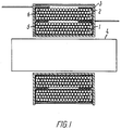
- the primary winding 1 and the secondary winding 2 are disposed coaxially one over the other in a common coil form 3 so that the two windings in their full length overlap each other.
- the coil form 3 surrounds on its side an iron core 4.
- Each of the windings 1 and 2 consists in a known manner of a considerable number of turns of lacquered copper wire wound in such a manner that each of the windings is imparted a mainly rectangular winding or copper cross-section.
- the primary winding 1 as well as the secondary winding 2 are provided with an insulation device according to the invention in the form of insulating layers 5 and 6 completely covering in the illustrated Example the internal side of each winding facing the core 4, and the end faces of the winding, and are further bent in over and cover at least part of the external side of the winding.
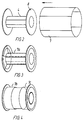
- the insulation layer is obtained in that a layer of foil material is firstly shaped to a tubular form 7 corresponding to the outer dimension of the end walls 8 of the coil form 3 or, if no coil form is used, the outer dimension of the coil itself or the winding.
- the foil layer 7 shaped to a tubular form is subsequently deformed to a substantially U-shaped cross-sectional profile 7a as illustrated in Fig. 3, corresponding to the coil form 3 or, if no coil form is used, to the winding cross-section of the coil.
- the U-shaped cross-sectional profile is provided with end portions 7b, 7c with such a radial width that they project so much beyond the intended winding width that after winding they may be bent in over the external side of the coil or winding and cover a substantial part of or possibly the entire of this side.
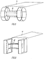
- Producing the insulation layer with the tubular form 7 prior to deforming it to the U-shaped cross-sectional profile may be effected by cutting from a blank extruded in a tubular form a suitable insulation material or, as illustrated in Figs 5 and 6, by any other method that is more appropriate for a practical production in that the coil form 10, 10' is wound with a webshaped insulation material 9, 9' to constitute the tubular form 7.
- the insulation material is a shrinkable material and the deformation to the U-shaped cross-sectional profile is effected by a shrinking process, preferably by controlled thermal stress.
- insulation devices 11 and 12 are thus arranged both around the primary winding 13 and the secondary winding 14 in such a manner that they cover the internal sides and end faces of both windings and further cover part of the external sides of the windings.
- Figs 8 and 9 show designs in which only the primary winding 13' and the secondary winding 14', respectively, have an insulation device 11' and 12', respectively, designed in the same manner as in Fig. 7.
- Fig. 10 illustrates an embodiment in which an insulation device 15 around a primary winding 16 completely encapsulates the winding also on its external side.
- FIG. 11 illustrates an insulation device 17 encapsulating a single coil winding 18.
- Figs 12 and 13 illustrate alternative embodiments forming for each of the illustrated primary and secondary windings 19, 19' and 20, 20', respectively, two separate insulation layers each from their respective foil material shaped to a tubular form as described in the foregoing and afterwards deformed to a substantially L-shaped cross-section covering part of the internal side of the winding and one end face thereof and of which an end portion is folded in over part of the external side of the winding.
- each of the windings 19 and 20 provided two separate insulation devices 21, 22 and 23, 24, respectively, covering only end portions of the windings whereas, in the embodiment in Fig. 13 there are for each of the windings 10' and 20' provided two separate insulation devices 25, 26 and 27, 28 overlapping each other on the internal side of the winding.
Landscapes
- Engineering & Computer Science (AREA)
- Power Engineering (AREA)
- Manufacturing & Machinery (AREA)
- Insulating Of Coils (AREA)
Applications Claiming Priority (3)
| Application Number | Priority Date | Filing Date | Title |
|---|---|---|---|
| DK120/92 | 1992-01-31 | ||
| DK12092A DK169799B1 (da) | 1992-01-31 | 1992-01-31 | Isolationsindretning for elektriske spoler og transformatorviklinger |
| PCT/DK1993/000031 WO1993015516A1 (en) | 1992-01-31 | 1993-01-28 | An insulation device for electrical coils and transformer windings |
Publications (2)
| Publication Number | Publication Date |
|---|---|
| EP0724765A1 EP0724765A1 (en) | 1996-08-07 |
| EP0724765B1 true EP0724765B1 (en) | 1997-09-03 |
Family
ID=8089978
Family Applications (1)
| Application Number | Title | Priority Date | Filing Date |
|---|---|---|---|
| EP93903857A Expired - Lifetime EP0724765B1 (en) | 1992-01-31 | 1993-01-28 | A method of manufacturing an electrical coil or transformer winding having an insulation device |
Country Status (5)
| Country | Link |
|---|---|
| EP (1) | EP0724765B1 (da) |
| AU (1) | AU3492393A (da) |
| DE (1) | DE69313671D1 (da) |
| DK (1) | DK169799B1 (da) |
| WO (1) | WO1993015516A1 (da) |
Families Citing this family (4)
| Publication number | Priority date | Publication date | Assignee | Title |
|---|---|---|---|---|
| US6326877B1 (en) * | 1999-06-16 | 2001-12-04 | Square D Company | Transformer coil support structure |
| BRPI0706119A2 (pt) * | 2007-10-02 | 2009-06-02 | Whirlpool Sa | processo de isolamento elétrico de uma bobina de um dispositivo elétrico e arranjo de isolamento elétrico de uma bobina de um dispositivo elétrico |
| ITUB20156089A1 (it) | 2015-12-02 | 2017-06-02 | Itacoil S R L | Nastro isolante per componenti elettrici |
| NO349491B1 (en) * | 2020-11-04 | 2026-02-02 | Seid As | High-voltage transformer for a plasma-based gas-treatment apparatus |
Family Cites Families (1)
| Publication number | Priority date | Publication date | Assignee | Title |
|---|---|---|---|---|
| GB8501455D0 (en) * | 1985-01-21 | 1985-02-20 | Gen Electric Co Plc | Electromagnetic transformers |
-
1992
- 1992-01-31 DK DK12092A patent/DK169799B1/da not_active IP Right Cessation
-
1993
- 1993-01-28 DE DE69313671T patent/DE69313671D1/de not_active Expired - Lifetime
- 1993-01-28 WO PCT/DK1993/000031 patent/WO1993015516A1/en not_active Ceased
- 1993-01-28 EP EP93903857A patent/EP0724765B1/en not_active Expired - Lifetime
- 1993-01-28 AU AU34923/93A patent/AU3492393A/en not_active Abandoned
Also Published As
| Publication number | Publication date |
|---|---|
| AU3492393A (en) | 1993-09-01 |
| DK12092D0 (da) | 1992-01-31 |
| DK169799B1 (da) | 1995-02-27 |
| DK12092A (da) | 1993-08-01 |
| WO1993015516A1 (en) | 1993-08-05 |
| DE69313671D1 (de) | 1997-10-09 |
| EP0724765A1 (en) | 1996-08-07 |
Similar Documents
| Publication | Publication Date | Title |
|---|---|---|
| US4901048A (en) | Magnetic core multiple tap or windings devices | |
| US4814735A (en) | Magnetic core multiple tap or windings devices | |
| US5202664A (en) | Three phase transformer with frame shaped winding assemblies | |
| US3958328A (en) | Method of making a transformer coil assembly | |
| GB2273819A (en) | Multi-core electric conductor insulation arrangement | |
| CN101454851A (zh) | 具有箔导体的盘绕式变压器及其制造方法 | |
| JPH06181135A (ja) | 配電用変圧器 | |
| AU2004248846B2 (en) | Three-phase transformer | |
| US7142085B2 (en) | Insulation and integrated heat sink for high frequency, low output voltage toroidal inductors and transformers | |
| US4592133A (en) | Method of constructing an electrical transformer | |
| EP1058279B1 (en) | Boosting transformer for high-frequency heating device | |
| EP0724765B1 (en) | A method of manufacturing an electrical coil or transformer winding having an insulation device | |
| US6492892B1 (en) | Magnet wire having differential build insulation | |
| JP2649881B2 (ja) | 高周波変圧器 | |
| JP2005158857A (ja) | モールドコイル | |
| US3657677A (en) | Electrical transformer | |
| JP2925792B2 (ja) | 高周波電源用薄形コイルの製造方法 | |
| US3702451A (en) | Electrical inductive apparatus | |
| US20040003492A1 (en) | Method for winding transformers | |
| JPH05175059A (ja) | 変圧器 | |
| US3648207A (en) | Apparatus for starting and operating electric discharge lamps | |
| TWI278874B (en) | Transformer using coil modules and related manufacturing method thereof | |
| US20040095220A1 (en) | Transformer using coil modules and related manufacturing method thereof | |
| JP2001067943A (ja) | コイル巻線用平角多層絶縁電線 | |
| RU2058606C1 (ru) | Способ изготовления электромагнитного элемента |
Legal Events
| Date | Code | Title | Description |
|---|---|---|---|
| PUAI | Public reference made under article 153(3) epc to a published international application that has entered the european phase |
Free format text: ORIGINAL CODE: 0009012 |
|
| 17P | Request for examination filed |
Effective date: 19940722 |
|
| AK | Designated contracting states |
Kind code of ref document: A1 Designated state(s): DE DK FR GB SE |
|
| GRAG | Despatch of communication of intention to grant |
Free format text: ORIGINAL CODE: EPIDOS AGRA |
|
| 17Q | First examination report despatched |
Effective date: 19961113 |
|
| GRAH | Despatch of communication of intention to grant a patent |
Free format text: ORIGINAL CODE: EPIDOS IGRA |
|
| GRAH | Despatch of communication of intention to grant a patent |
Free format text: ORIGINAL CODE: EPIDOS IGRA |
|
| GRAA | (expected) grant |
Free format text: ORIGINAL CODE: 0009210 |
|
| AK | Designated contracting states |
Kind code of ref document: B1 Designated state(s): DE DK FR GB SE |
|
| PG25 | Lapsed in a contracting state [announced via postgrant information from national office to epo] |
Ref country code: FR Free format text: LAPSE BECAUSE OF FAILURE TO SUBMIT A TRANSLATION OF THE DESCRIPTION OR TO PAY THE FEE WITHIN THE PRESCRIBED TIME-LIMIT Effective date: 19970903 Ref country code: DK Free format text: LAPSE BECAUSE OF NON-PAYMENT OF DUE FEES Effective date: 19970903 |
|
| REF | Corresponds to: |
Ref document number: 69313671 Country of ref document: DE Date of ref document: 19971009 |
|
| PG25 | Lapsed in a contracting state [announced via postgrant information from national office to epo] |
Ref country code: SE Effective date: 19971203 |
|
| PG25 | Lapsed in a contracting state [announced via postgrant information from national office to epo] |
Ref country code: DE Effective date: 19971204 |
|
| PG25 | Lapsed in a contracting state [announced via postgrant information from national office to epo] |
Ref country code: GB Free format text: LAPSE BECAUSE OF NON-PAYMENT OF DUE FEES Effective date: 19980128 |
|
| EN | Fr: translation not filed | ||
| PLBE | No opposition filed within time limit |
Free format text: ORIGINAL CODE: 0009261 |
|
| STAA | Information on the status of an ep patent application or granted ep patent |
Free format text: STATUS: NO OPPOSITION FILED WITHIN TIME LIMIT |
|
| 26N | No opposition filed | ||
| GBPC | Gb: european patent ceased through non-payment of renewal fee |
Effective date: 19980128 |