EP0724954B1 - Verfahren und Vorrichtung zum Falten eines Etiketts - Google Patents
Verfahren und Vorrichtung zum Falten eines Etiketts Download PDFInfo
- Publication number
- EP0724954B1 EP0724954B1 EP95810822A EP95810822A EP0724954B1 EP 0724954 B1 EP0724954 B1 EP 0724954B1 EP 95810822 A EP95810822 A EP 95810822A EP 95810822 A EP95810822 A EP 95810822A EP 0724954 B1 EP0724954 B1 EP 0724954B1
- Authority
- EP
- European Patent Office
- Prior art keywords
- drum
- blank
- rail
- surface portion
- disposed
- Prior art date
- Legal status (The legal status is an assumption and is not a legal conclusion. Google has not performed a legal analysis and makes no representation as to the accuracy of the status listed.)
- Expired - Lifetime
Links
- 238000000034 method Methods 0.000 title claims description 19
- 238000007493 shaping process Methods 0.000 claims description 32
- 238000011144 upstream manufacturing Methods 0.000 claims description 15
- 238000003825 pressing Methods 0.000 claims description 6
- 230000000694 effects Effects 0.000 claims description 4
- 239000000853 adhesive Substances 0.000 claims description 3
- 230000001070 adhesive effect Effects 0.000 claims description 3
- 241000135309 Processus Species 0.000 description 2
- 230000015572 biosynthetic process Effects 0.000 description 2
- 230000003247 decreasing effect Effects 0.000 description 2
- 239000003292 glue Substances 0.000 description 2
- 239000000463 material Substances 0.000 description 2
- 241001417494 Sciaenidae Species 0.000 description 1
- 230000001154 acute effect Effects 0.000 description 1
- 230000000295 complement effect Effects 0.000 description 1
- 235000009508 confectionery Nutrition 0.000 description 1
- 238000010276 construction Methods 0.000 description 1
- 230000007423 decrease Effects 0.000 description 1
- 238000000151 deposition Methods 0.000 description 1
- 238000006073 displacement reaction Methods 0.000 description 1
- 239000000835 fiber Substances 0.000 description 1
- 230000001788 irregular Effects 0.000 description 1
- 238000004806 packaging method and process Methods 0.000 description 1
- 239000000725 suspension Substances 0.000 description 1
Images


Classifications
-
- B—PERFORMING OPERATIONS; TRANSPORTING
- B31—MAKING ARTICLES OF PAPER, CARDBOARD OR MATERIAL WORKED IN A MANNER ANALOGOUS TO PAPER; WORKING PAPER, CARDBOARD OR MATERIAL WORKED IN A MANNER ANALOGOUS TO PAPER
- B31F—MECHANICAL WORKING OR DEFORMATION OF PAPER, CARDBOARD OR MATERIAL WORKED IN A MANNER ANALOGOUS TO PAPER
- B31F1/00—Mechanical deformation without removing material, e.g. in combination with laminating
- B31F1/0003—Shaping by bending, folding, twisting, straightening, flattening or rim-rolling; Shaping by bending, folding or rim-rolling combined with joining; Apparatus therefor
- B31F1/0006—Bending or folding; Folding edges combined with joining; Reinforcing edges during the folding thereof
- B31F1/0009—Bending or folding; Folding edges combined with joining; Reinforcing edges during the folding thereof of plates, sheets or webs
- B31F1/0019—Bending or folding; Folding edges combined with joining; Reinforcing edges during the folding thereof of plates, sheets or webs the plates, sheets or webs moving continuously
- B31F1/0029—Folding edges; Folding edges combined with joining; Reinforcing edges during the folding thereof, e.g. by introducing a thread; Folding the edges of a sheathing
-
- B—PERFORMING OPERATIONS; TRANSPORTING
- B31—MAKING ARTICLES OF PAPER, CARDBOARD OR MATERIAL WORKED IN A MANNER ANALOGOUS TO PAPER; WORKING PAPER, CARDBOARD OR MATERIAL WORKED IN A MANNER ANALOGOUS TO PAPER
- B31B—MAKING CONTAINERS OF PAPER, CARDBOARD OR MATERIAL WORKED IN A MANNER ANALOGOUS TO PAPER
- B31B50/00—Making rigid or semi-rigid containers, e.g. boxes or cartons
- B31B50/26—Folding sheets, blanks or webs
- B31B50/36—Folding sheets, blanks or webs by continuously feeding the sheets, blanks or webs to stationary members, e.g. plates, ploughs or cores
-
- B—PERFORMING OPERATIONS; TRANSPORTING
- B31—MAKING ARTICLES OF PAPER, CARDBOARD OR MATERIAL WORKED IN A MANNER ANALOGOUS TO PAPER; WORKING PAPER, CARDBOARD OR MATERIAL WORKED IN A MANNER ANALOGOUS TO PAPER
- B31B—MAKING CONTAINERS OF PAPER, CARDBOARD OR MATERIAL WORKED IN A MANNER ANALOGOUS TO PAPER
- B31B50/00—Making rigid or semi-rigid containers, e.g. boxes or cartons
- B31B50/60—Uniting opposed surfaces or edges; Taping
- B31B50/62—Uniting opposed surfaces or edges; Taping by adhesives
- B31B50/622—Applying glue on already formed boxes
Definitions
- the present invention relates firstly to a method by which a first portion of a label is folded over a second portion of the same label according to the preamble of claim 1. It also relates to a device capable of carrying out said method.
- Patent EP-B-0.514 340 describes a method and a device by which various operations are carried out for the preparation of a packaging blank, respectively of a label.
- the device described in particular comprises a drum on the cylindrical lateral surface of which a label is maintained, various preparation operations being successively carried out during the rotation of the drum.
- One of these operations consists in folding down a first portion of the label by 180 ° onto a second portion of the same label.
- the patent in question indicates that this operation is carried out using a semi-helical guide rail. Since the label is placed on a cylindrical drum, the fold line around which the fold is to be made is arched according to the diameter of the drum.
- a first object of the present invention is therefore to precisely define a method by which this folding operation is carried out, while a second object of the invention, as defined in the claims 5 to 11, is to specify the characteristics of a folding device suitable for this operation.
- FIG. 1 shows a label 1 held on the external cylindrical surface of a rotating drum 2, the label being arranged longitudinally and parallel to the axis of rotation of the drum, folding means 3 being provided for folding down the portion 10 of the label 1 on the portion 11 around the range line 12; pressure roller means 4 are arranged at the outlet of the pad means 3 in order to consolidate the fold or, if necessary, if a drop of glue has been placed on one of the portions 10 or 11 before the fold is carried out, by means not shown arranged upstream of the folding means 3, to consolidate the bonding of the folded portion.
- the drum 2 comprises in particular a first support disc 20 on which the portion of the label 1 close to the fold line 11 is supported.
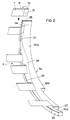
- FIG. 2 represents, seen in perspective, the guide or shaping rail 30, which is the main element of the folding device 3 according to the invention, on which a plurality of label portions 1 are seen to pass, in order to describe the different stages of folding down the surface portion 10 on the adjacent portion 11 around the fold line 12.
- the rail 30 is here shown seen from its concave face.
- the portions represented of the labels 1 relate only to the central part at the end of the label 1, the shape of the latter having been simplified compared to the shape shown in the figure. 1 so as not to overload the figure.
- the label 1 is maintained on the drum 2, not shown in this figure, the different labels represented here corresponding to different angular positions of the drum, respectively various stages of the process.
- the shaping rail 30 consists of a preferably metallic piece, having the general shape of a circular crown segment, of relatively small thickness. It comprises a first portion 30A extending over approximately a third of the length of the rail 30, followed by a second portion 30B extending over most of the length of the rail 30, then a third portion 30C, relatively short and constituting the end of the rail 30. As can best be seen in FIG.
- the edge 31 on the first portion 30A of the rail 30 directed towards the drum 2, respectively towards the first support disc 20, is perpendicular to the longitudinal axis of said drum, while the same edge 32 on the second portion 30B takes the form of a helix directed towards the drum 2, and that the edge 33 corresponding to the portion 30C is again perpendicular to the longitudinal axis of the drum 2.
- the outer face of the portion 30A, respectively the convex part of this portion of the rail 30 is cut in a bevel so as to have a surface 34 in the form of a portion of a truncated cone inclined towards the edge 31 , the axis of said truncated cone being coincident with the axis of rotation of the drum 2; the theoretical apex of this truncated cone would be on said axis, in the direction of the drum. It can be seen in FIG.
- this surface 34 has a general shape of a triangle, that its height increases rapidly from the upstream end of the porton 30A, ie from the nose 35 of said portion, to a maximum value and then slowly decreases until the end of portion 30A. It may be recalled that the end of this surface 34 facing the drum 2, respectively the edge 31 is perpendicular to the axis of the drum 2.
- this surface 36 On the other face of the rail 30, that is to say on the concave part of the latter, there is also a bevel cut, defining another surface 36, also in shape portion of truncated cone, the axis of which also coincides with the axis of rotation of the drum 2, but the apex of which is in the direction opposite to that of the drum.
- the intersection of this surface 36 with the internal face of the rail has the general shape of a triangle, its height increasing from a point located near the nose 35 of the portion 30A, to a maximum value located on the meeting line between the portions 30A and 30B then decreasing on the portion 30B to cancel out on the meeting line between the portions 30B and 30C.
- the end of this surface 36 facing the drum therefore corresponds to the edge 31 on the portion 30A and then to the edge 32 of helical shape on the portion 30B.
- the surface 37 corresponding to the concave internal face of the portion 30C simply has the shape of a circular cylindrical portion.
- FIGS. 3B and 5B show a portion of a label 1 seen in profile, arranged on the drum 2 in rotation and moving towards the shaping rail 30 in order to fold the surface portion 10 around the fold line 12 to fold it over the surface portion 11 as indicated by the arrow.
- FIG. 3B it can be seen that the label 1 is held on the drum 2 in a position such that the fold line 12 is very slightly set back towards the drum relative to the edge 31 of the portion 30A.
- the different folding steps can now be followed in FIG. 2.
- the label 1 therefore comes upstream of the portion 30A of the rail 30, being positioned as we have just seen.
- the portion 10 of the label engages on the convex part of the rail 30, respectively on the surface 34 located on the other side of the rail 30 as shown in Figure 2 where the portion 10 begins to fold, being guided by the surface 34.
- the folding angle increases regularly until reaching 90 ° when the label reaches the end of the portion 30A, ie at the start of the portion 30B, respectively at the point where the helical edge 32 begins.
- the label is then guided by the surface 36 located on the concave face of the rail 30 where the fold continues to form until the surface portion 10 is completely folded over the portion 11 when the label 1 arrives on the portion 30C.
- the surface portion 10 of the label 1 has been folded back 180 ° from the entry to the exit of the label on the rail 30.
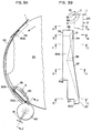
- FIGS. 3A and 3B a first embodiment of the means for holding and guiding the label is shown in FIGS. 3A and 3B, their operation being described with reference to FIGS. 4A to 4F.
- These holding means 5 are arranged on the first support disc 20, which in this case has a support surface, on which the label 1 rests, wider than that shown in FIG. 1, or which can be offset in the direction of the shaping rail 30, so that the label 1 can rest on this surface up to the fold line 12 (see upper part of FIG. 3B).
- suction nozzles 50 On this bearing surface of the disc 20, suction nozzles 50 have been distributed along the same generatrices of the drum 2 as the suction nozzles described in the patent mentioned above.
- the suction nozzles 50 are connected to the same suction device as the suction nozzles of the patent mentioned above and operate simultaneously with them. If it is desired that the label 1 remains flat during folding, it is possible to provide a frame 51 surrounding the mouth of each nozzle 50 on the bearing surface of the disc 20, thus defining a plane bearing surface, or then create a flat at the mouth of each nozzle 40 (see FIG. 3A).
- FIGS. 4A to 4F Several stages of the folding process are shown in FIGS. 4A to 4F which correspond respectively to the state of the label 1 along lines A to F of FIGS. 3A and 3B.
- FIG. 4A the label 1 has not yet entered the folding device, it is firmly held on the support disc 20, in particular by a suction nozzle 50.
- FIG. 4B the portion 10 has then been slid on the convex side of the portion 30A of the shaping rail 30 and is therefore supported on the surface 34 which begins to form the fold.
- FIG. 4C also shows a subsequent step where the portion 30A already includes the surface 36 on its concave face, the folding here is mainly carried out by the edge 31 which is always parallel to the fold 12. In the step shown in FIG.
- the portion 10 has tilted from the convex face to the concave face of the rail 30, over the helical edge 32 and is now guided by the surface 36 of the portion 30B of the shaping rail 30.
- This tilting operation is caused by the offset of the rail 30 relative to the disc 20 as described below.
- the portion 10 is completely folded over the portion 11, the fold being held by the surface 37 against the surface d support of the support disc 20. In order to fully form the fold 12, it is then crushed by a roller 40 pressing firmly against the support surface of the disc 20.
- the roller 40 is mounted on suspension means 41, for example spring-loaded, so as to be able to maintain a constant pressure despite the shape irregular of the bearing surface of the disc 20. It was indicated in the aforementioned patent that a device for depositing one or more spots of adhesive was placed before the pad device so that after folding the portion surface 10 ad hère on the corresponding portion 11; the support exerted by the roller 40 on the portion 10 folded over the portion 11 bearing on the bearing surface of the bearing disc 20 makes it possible to consolidate this bonded bond. On examining FIGS.
- the rail 30, respectively its portions 30A, 30B and 30C or the edges 31 and 32 move relatively to the bearing surface of the bearing disc 20; this is not the case, the rail 30 is absolutely fixed, this effect of relative displacement being obtained by an offset of the surfaces of the cylindrical segment of the rail 30 relative to the cylindrical periphery of the support disc 20, so that the nose 35 of the portion 30A is tangent or slightly inside the envelope of the periphery of the support disc 20 and the portion 30C is slightly spaced from this periphery (see FIG. 3A), the support surface 37 of said portion 30C then being coaxial with the cylindrical bearing surface of the disc 31 in order to keep the fold closed, maintained between the two said surfaces, as seen in FIG. 4E.
- the edge 31, 32 of the shaping rail 30 progressively passes from a tangent position or below the cylindrical bearing surface of the disc to an external position, parallel to said cylindrical bearing surface, label 1 exactly following the periphery of disc 31, will see its portion 10 engage on the surface 34 disposed outside of the rail 30 then later after having tilted over the edge 31.32 at the moment when said edge crosses the cylindrical bearing surface of the disc, it will see said portion 10 follow the surfaces 36 then 37 located inside the rail 30.
- the second embodiment of the holding and guiding means described below corresponds to the preferred embodiment of these; this embodiment is shown in Figures 5A and 5B, different stages of the action of these means during the folding process being shown in Figures 6A to 6G in the same manner as above.
- the folding and holding means according to this embodiment consist only of fixed and stationary elements excluding the drum 2 in rotation.
- the shaping rail 30 is absolutely identical to that described above, but unlike the previous embodiment, the support disc 20 no longer comes in close proximity to the fold line 12 but is clearly set back from this line, as shown in FIG. 5B.
- the means 6 for holding the label 1 during the folding operation comprise, apart from those described in the patent mentioned above and arranged on the drum 2, a first internal support rail 60 and a second external support rail 61 provided with a support tab 62, these elements as well as the shaping rail 30 being fixed and immobile.
- the first internal support rail 60 consists of a circular ring segment generally disposed inside the concave surface of the rail 30, so as to present a cylindrical offset support surface 63 in the exact extension of the surface support of the disc 20, it generally provides support on the back of the label 1 before and during the folding thereof; consequently, the circumference portion covered by the rail 60 also extends upstream from that covered by the rail 30.
- the second external support rail 61 also consists of a circular crown segment; it is arranged parallel to the rail 60, on the side of the drum 2, but is not exactly coaxial with it.
- the concave face of this rail 61 has a cylindrical surface 64 disposed opposite the bearing surface 63 of the rail 60, the spacing between the surfaces 64 and 63 decreasing, passing from a large spacing towards the upstream parts of the rails 60 and 61, leaving the label 1 relatively free between the surfaces 63 and 64, at a reduced spacing towards the parts downstream of said rails where the folded portion 10 is pressed on the portion 11 of the label 1 as we will see below.
- a portion of the back of the label 1 rests on a portion of the bearing surface 63 of cylindrical shape while a portion of the opposite face of the label 1 is guided or maintained by the second support rail 61.
- the fold line 12 will therefore take an arcuate shape during said path.
- the essential part of the second support rail 61 consists of a support tongue 62 projecting from a portion of a circle on the inside of the rail 61 closest to the shaping rail 30, said tongue having an edge directed towards the bearing surface 63 of the rail 60 and whose length and position correspond approximately to that of the portion of the surface 36 located on the portion 30A of the rail 30. (see FIG. 5B).
- the way in which the shaping rail 30 cooperates with the holding means consisting of the first support rail 60 and the second support rail 61 described above, in order to make the fold around the beach line 12, is shown in Figures 6A to 6G.
- the label 1 is held on the drum 2 as described in the previously mentioned patent.
- its portion disposed behind the folding line 12, ie on the side of the rest of the label 1 comes to bear on the bearing surface 63 of the inner bearing rail 60 and engages under the bearing surface 64 of the outer bearing rail 61 without coming into direct contact with said surface.
- the portion 10 of the label 1 meets the surface 34 of the portion 30A of the shaping rail 30.
- the end of label 1 is slightly raised; due to the spacing of the two bearing surfaces 63 and 64, the portion of the label 1 comprising the fold line 12 can be straightened so as to be relatively straight in this place, that is to say not arcuate .
- the fold around the fold line 12 can be initiated before the latter is arched again.
- the fold is accentuated even that the label has an arcuate shape, the surface portion slightly behind the beach line 12 being strongly pressed by the edge of the tongue 62 against the surface d 'support 63.
- the fold is more and more pronounced; the pinching of the label 1 between the edge of the tongue 62 and the bearing surface 63 giving the arcuate shape described in the fold line, cooperating with the increase in the folding angle caused by the surface of support in the form of a truncated cone portion 34 creates a tilting of the surface portion 10 around the arcuate fold line 12, the fold being now guided by the edge 31.
- FIG. 6E it can be seen that the label 1, after the mentioned tilting, has passed on the other side of the rail 30, and is now opposite the portion 30B of the rail 30. It is the surface 36, the edge 32 of which has the helical shape mentioned previously , which contributes to continuing the formation of the fold.
Landscapes
- Engineering & Computer Science (AREA)
- Mechanical Engineering (AREA)
- Labeling Devices (AREA)
- Making Paper Articles (AREA)
Claims (11)
- Verfahren, durch welches ein erster Oberflächenteil (10) angeordnet an einem Ende eines Etiketts (1) um 180° um eine Biegelinie (12) auf einen zweiten Oberflächenteil (11) des genannten Etiketts umgebogen wird, benachbart dem genannten ersten Oberflächenteil, wobei das Etikett der Länge nach angeordnet ist, und auf einer Mantellinie einer rotierenden Trommel (2) gehalten wird, wobei mindestens der genannte erste Oberflächenteil (10) eine kreisförmige Endfläche der genannten Trommel überragt, wobei die Biegelinie (12) senkrecht zur Rotationsachse der Trommel (2) ist, eine Schiene (30) zum in Form bringen die allgemeine Form eines kreisförmigen Ringsegmentes aufweist, welches in der Nähe des genannten Endes der Trommel (2) angeordnet ist, und eine Kante (31, 32, 33) aufweist, die gegen die genannte Trommel gerichtet ist, auf eine solche Weise, dass die konvexe Fläche des Teiles (30A) hinten an der genannten Schiene tangential oder leicht unterhalb der zylindrischen Oberfläche, die durch die umhüllende der Trommel gebildet wird angeordnet ist, wobei die konkave Fläche des Teils (30C) vorne an der genannten Schiene leicht oberhalb und koaxial mit der genannten zylindrischen Fläche angeordnet ist, wobei das Verfahren durch folgende Schritte gekennzeichnet ist:der erste Oberflächenteil (10) der Etiketts (1) wird auf die konvexe Fläche des Endes hinter einem ersten Längenteil (30A) der genannten Schiene zum in Form bringen zugeführt, auf welcher die genannte Kante (31), die gegen die Trommel (2) gerichtet ist, im allgemeinen parallel zur genannten Biegelinie (12) ist, wo unter dem Effekt der Vorwärtsbewegung des genannten ersten Oberflächenteils (10) gegen eine abgeschrägte kegelstumpfförmige Oberfläche (34), die auf der genannten konvexen Fläche angeordnet ist, der genannte erste Oberflächenteil (10) sich zu biegen beginnt, der genannte erste Oberflächenteil danach oberhalb der genannten Kante der Schiene zum in Form bringen (32) durchtritt, um auf die konkave Fläche (36) eines zweiten Teils (30B) der Länge der genannten Schiene zum in Form bringen zugeführt zu werden, auf welcher die genannte Kante (32) die gegen die Trommel gerichtet ist, von gegen die Trommel gerichteter spiralförmiger Form ist, wo unter dem Effekt der Vorwärtsbewegung des genannten ersten Oberflächenteils (10) gegen eine andere abgeschrägte Oberfläche (36) in Form eines Kegelstumpfes dieser ganz gegen den genannten zweiten Oberflächenteil (11) umgebogen wird,wobei Mittel zum Halten und Führen (5, 6) mit der genannten Schiene zum in Form bringen zusammenwirken, vorgesehen sind um zum Halten und Führen des Etiketts während der Tätigkeit des Faltens.
- Verfahren nach Patentanspruch 1, wo die Halte- und Führungsmittel (6) aus einer ersten inneren Führungsschiene (60) und aus einer zweiten äusseren Führungsschiene (61) bestehen, wobei der Rücken des zweiten Teils der Oberfläche (11) des Etiketts sich gegen eine äussere zylindrische Oberfläche (63) der ersten inneren Führungsschiene stützt, wobei die äussere zylindrische Oberfläche in der Verlängerung der zylindrischen Oberfläche der Trommel (2) liegt, der zweite Oberflächenteil (11) des Etiketts gegen die genannte äussere zylindrische Oberfläche der ersten inneren Führungsschiene durch einen vorstehenden Lappen (62) gedrückt wird, welcher Teil der zweiten externen Führungsschiene (61) ist und beiderseits vom Längenteil der Schiene zum in Form bringen (30) angeordnet ist, wo der genannte erste Oberflächenteil (11) des Etiketts oberhalb der Kante (32) der genannten Schiene zum in Form bringen durchtritt.
- Verfahren nach Patentanspruch 1, wo die Haltemittel (5) aus Ansaugmitteln (50) bestehen, welche auf einer Stützfläche einer Stützscheibe (20) der Trommel (2) angeordnet sind, und die Rückseite des zweiten Teils der Oberfläche (11) des Etiketts sich auf die genannte Stützfläche bis zur Biegelinie (12) abstützt, der genannte erste Oberflächenteil (10) ausserhalb der genannten Stützfläche angeordnet ist.
- Verfahren nach einem der Patentansprüche 2 oder 3, wo die bogenförmige Faltlinie (12) durch Mittel (51; 63, 64) gerichtet wird, um die Faltung des genannten ersten Teils der Oberfläche (10) um die genannte Faltlinie (12) einzuleiten.
- Vorrichtung zum Umlegen um 180° eines ersten Oberflächenteils (10) der an einem Ende eines Etiketts (1) angeordnet ist, um eine Faltlinie (12) auf einen zweiten Oberflächenteil (11) des genannten Etiketts benachbart am genannten ersten Oberflächenteil, wobei das Etikett der Länge nach angeordnet ist und auf einer Mantellinie einer in Rotation befindlichen Trommel (2) gehalten ist, wobei mindestens der genannte erste Oberflächenteil (10) eine kreisförmige Endfläche der genannten Trommel überragt und die Faltlinie (12) senkrecht zur Rotationsachse der Trommel ist, dadurch gekennzeichnet, dassdie genannte Vorrichtung eine feste Schiene zum in Form bringen (30) umfasst, welche die allgemeine Form eines kreisförmigen Ringsegmentes aufweist und in der Nähe der genannten Endfläche der Trommel (2) angeordnet ist, und eine Kante (31, 32, 33) aufweist, die gegen die Trommel gerichtet ist und die konvexe Fläche des hinteren Endes (30A) der genannten Schiene tangentiell oder leicht unterhalb der zylindrischen Oberfläche angeordnet ist, welche durch die Umhüllende der Trommel (2) gebildet wird, wobei die konkave Fläche des anderen Endes (30C) der genannten Schiene leicht oberhalb und koaxial zur genannten zylindrischen Fläche angeordnet ist,die konvexe Fläche eines ersten Längenteils (30A) gegen das hintere Ende der genannten Schiene zum in Form bringen eine abgeschrägte Oberfläche (34) in Form eines Kegelstumpfes aufweist, wobei die gegen die Trommel (2) gerichtete Kante (31) im allgemeinen parallel zur Faltlinie (12) auf dem genannten ersten Längenteil (30A) ist, die konkave Fläche des genannten ersten Längenteils (30A) und eines zweiten Längenteils (30B) benachbart der genannten Schiene zum in Form bringen eine andere abgeschrägte Oberfläche (36) in Form eines Kegelstumpfes aufweisen, die genannte Kante (32) gegen die Trommel auf dem genannten zweiten Längenteil (30B) gerichtet ist und eine spiralförmige, in Richtung der Trommel gerichtete Form aufweist undMittel zum Halten und Führen (5; 6) des Etiketts (1) mit der genannten Schiene zum in Form bringen zusammenwirken.
- Vorrichtung nach Patentanspruch 5, wobei die Halte- und Führungsmittel (6) des Etiketts (1) aus einer ersten inneren Führungsschiene (60) bestehen, welche eine äussere zylindrische Oberfläche (63) umfasst, die in der Verlängerung der Oberfläche der zylindrischen Umhüllung der Trommel (2) angeordnet ist und einer zweiten äusseren Führungsschiene (61), welche einen vorstehenden Lappen (62) umfasst, dessen Kante parallel zur Biegungslinie (12) ist und teilweise gegenüber dem ersten Längenteil (30A) und teilweise gegenüber dem zweiten Längenteil (30B) der Schiene zum in Form bringen (30) angeordnet ist.
- Vorrichtung nach Patentanspruch 5, in welcher die zweite äussere Führungsschiene (61) hinter dem genannten vorstehenden Lappen (62) eine konkave Stützfläche (64) umfasst, welche mit Abstand von der äusseren zylindrischen Oberfläche (63) der ersten inneren Stützschiene (60) angeordnet ist, wobei der Abstand der beiden genannten Flächen das Geraderichten der Biegelinie (12) erlaubt, um die Faltung des ersten Oberflächenteils (10) des Etiketts (1) um die genannte Biegelinie (12) einzuleiten.
- Vorrichtung nach Patentanspruch 5, welche im weiteren Mittel zum Ablagern von mindestens einem Tropfen Klebstoff auf dem genannten zweiten Teil des Etiketts (11) umfasst, welche hinter oder gegen das hintere Ende der genannten Schiene zum in Form bringen (30) angeordnet sind, wie auch Druckmittel (4), welche aus zwei Druckrollen (40, 42) gebildet sind, die vorne an der genannten Schiene zum in Form bringen angeordnet sind, wobei die genannten Druckrollen, welche den ersten Oberflächenteil (10) des Etiketts stützen, welches komplett auf den zweiten Oberflächenteil (11) umgelegt ist.
- Vorrichtung nach Patentanspruch 5, wobei die Halte- und Führungsmittel (5) des Etiketts aus einer Stützscheibe (20) gebildet werden, welche einen Teil der Trommel (2) bildet, die eine zylindrische oder plane Stützfläche aufweist, auf welcher die Rückseite des zweiten Oberflächenteils (11) des Etiketts bis zur Faltlinie (12) abgestützt ist, der genannte erste Oberflächenteil (10) ausserhalb der genannten Stützfläche angeordnet ist, die genannte Stützscheibe pneumatische Ansaugmittel (50) umfasst, um das Etikett auf der genannten Stützfläche zu halten, im speziellen während der Tätigkeit des Umfaltens.
- Vorrichtung nach Patentanspruch 9, in welcher die Stützfläche der genannten Stützscheibe (20) Stützmittel (51) umfasst, welche erlauben, das Etikett eben auf der genannten Stützscheibe zu halten.
- Vorrichtung nach einem der Patentansprüche 9 oder 10, umfassend im weiteren Mittel zum Ablagern von mindestens einem Tropfen Klebstoff auf dem genannten zweiten Teil (11) des Etiketts, welche hinten an oder gegen das Ende hinten an der genannten Schiene zum in Form bringen (30) angeordnet sind, wie Druckmittel (4), die aus einer Druckrolle (40) bestehen, welche vorne an der genannten Schiene zum in Form bringen angeordnet sind, wobei die genannte Druckrolle auf den ersten Oberflächenteil (10) des Etiketts drückt, welches komplett auf den zweiten Oberflächenteil (11) gefaltet ist, in Abstützung auf die Stützoberfläche der genannten Stützscheibe (20).
Applications Claiming Priority (2)
| Application Number | Priority Date | Filing Date | Title |
|---|---|---|---|
| US08/371,345 US5716313A (en) | 1991-05-16 | 1995-01-11 | Apparatus and method for folding blanks |
| US371345 | 1995-01-11 |
Publications (2)
| Publication Number | Publication Date |
|---|---|
| EP0724954A1 EP0724954A1 (de) | 1996-08-07 |
| EP0724954B1 true EP0724954B1 (de) | 1997-11-12 |
Family
ID=23463586
Family Applications (1)
| Application Number | Title | Priority Date | Filing Date |
|---|---|---|---|
| EP95810822A Expired - Lifetime EP0724954B1 (de) | 1995-01-11 | 1995-12-29 | Verfahren und Vorrichtung zum Falten eines Etiketts |
Country Status (3)
| Country | Link |
|---|---|
| US (1) | US5716313A (de) |
| EP (1) | EP0724954B1 (de) |
| DE (1) | DE69501037T2 (de) |
Families Citing this family (23)
| Publication number | Priority date | Publication date | Assignee | Title |
|---|---|---|---|---|
| IT1292615B1 (it) * | 1997-06-10 | 1999-02-08 | Gd Spa | Metodo di rilevamento di materiale adesivo su uno sbozzato per un contenitore di articoli da fumo. |
| JP3568462B2 (ja) * | 2000-07-10 | 2004-09-22 | 日東電工株式会社 | 封緘装置 |
| US6575886B1 (en) * | 2001-02-01 | 2003-06-10 | Nigrelli Systems, Inc. | High speed wrap-around multipacker |
| FR2831147B1 (fr) * | 2001-10-19 | 2004-02-06 | Leroux Gilles Sa | Dispositif de transport dans un systeme d'embossage de carte |
| TWI350792B (en) * | 2007-01-17 | 2011-10-21 | Bobst Sa | Folding device for a folding and gluing machine |
| EP1946918B1 (de) * | 2007-01-17 | 2011-04-20 | Bobst Sa | Biegevorrichtung für eine Biege-Klebe-Presse |
| DE102007057820C5 (de) * | 2007-11-30 | 2020-07-16 | Windmöller & Hölscher Kg | Gegenlage Düsenbeleimung |
| ES2939598T3 (es) | 2011-11-10 | 2023-04-25 | Packsize Llc | Máquina de conversión elevada con guía de extracción |
| US10052838B2 (en) * | 2012-01-09 | 2018-08-21 | Packsize Llc | Converting machine with an upward outfeed guide |
| US10093438B2 (en) | 2014-12-29 | 2018-10-09 | Packsize Llc | Converting machine |
| JP7043426B2 (ja) | 2016-06-16 | 2022-03-29 | パックサイズ・リミテッド・ライアビリティ・カンパニー | 箱テンプレート製造システムおよび方法 |
| US10850469B2 (en) | 2016-06-16 | 2020-12-01 | Packsize Llc | Box forming machine |
| US11242214B2 (en) | 2017-01-18 | 2022-02-08 | Packsize Llc | Converting machine with fold sensing mechanism |
| SE541921C2 (en) | 2017-03-06 | 2020-01-07 | Packsize Llc | A box erecting method and system |
| SE1750727A1 (sv) | 2017-06-08 | 2018-10-09 | Packsize Llc | Tool head positioning mechanism for a converting machine, and method for positioning a plurality of tool heads in a converting machine |
| US11173685B2 (en) | 2017-12-18 | 2021-11-16 | Packsize Llc | Method for erecting boxes |
| US11305903B2 (en) | 2018-04-05 | 2022-04-19 | Avercon BVBA | Box template folding process and mechanisms |
| US11247427B2 (en) | 2018-04-05 | 2022-02-15 | Avercon BVBA | Packaging machine infeed, separation, and creasing mechanisms |
| WO2019246344A1 (en) | 2018-06-21 | 2019-12-26 | Packsize Llc | Packaging machine and systems |
| SE543046C2 (en) | 2018-09-05 | 2020-09-29 | Packsize Llc | A box erecting method and system |
| US11524474B2 (en) | 2018-11-30 | 2022-12-13 | Packsize Llc | Adjustable cutting and creasing heads for creating angled cuts and creases |
| WO2020146334A1 (en) | 2019-01-07 | 2020-07-16 | Packsize Llc | Box erecting machine |
| US11701854B2 (en) | 2019-03-14 | 2023-07-18 | Packsize Llc | Packaging machine and systems |
Family Cites Families (7)
| Publication number | Priority date | Publication date | Assignee | Title |
|---|---|---|---|---|
| US1426608A (en) * | 1921-01-17 | 1922-08-22 | Jacob B Schmidt | Box-blank machine |
| US4132156A (en) * | 1977-06-21 | 1979-01-02 | Intech Corporation | Rotary tray former |
| DE3910986A1 (de) * | 1989-04-05 | 1990-10-11 | Focke & Co | Verfahren und vorrichtung zum herstellen von (zigaretten -) packungen |
| IT1245765B (it) * | 1991-02-26 | 1994-10-14 | Gd Spa | Metodo e dispositivo per la piegatura di alette terminali di sbozzati di pacchetti di sigarette rigidi a coperchio incernierato. |
| DE69200610T2 (de) * | 1991-05-16 | 1995-05-18 | Tabac Fab Reunies Sa | Verfahren und Vorrichtung zum Vorbereiten von Verpackungszuschnitten. |
| US5188582A (en) * | 1991-05-31 | 1993-02-23 | Boardman Molded Products, Inc. | Apparatus for forming tear tab lining material |
| DE9406215U1 (de) * | 1994-04-14 | 1994-08-11 | Fa. Alfred Klett, 42899 Remscheid | Faltmaschine |
-
1995
- 1995-01-11 US US08/371,345 patent/US5716313A/en not_active Expired - Fee Related
- 1995-12-29 EP EP95810822A patent/EP0724954B1/de not_active Expired - Lifetime
- 1995-12-29 DE DE69501037T patent/DE69501037T2/de not_active Expired - Lifetime
Also Published As
| Publication number | Publication date |
|---|---|
| EP0724954A1 (de) | 1996-08-07 |
| DE69501037T2 (de) | 1998-06-10 |
| DE69501037D1 (de) | 1997-12-18 |
| US5716313A (en) | 1998-02-10 |
Similar Documents
| Publication | Publication Date | Title |
|---|---|---|
| EP0724954B1 (de) | Verfahren und Vorrichtung zum Falten eines Etiketts | |
| EP0938427B1 (de) | Maschine zum formen, füllen und verschliessen von beuteln mit transversalen verschlussprofilen, und hergestellte beutel | |
| EP0605268B1 (de) | Verpackung mit vieleckigem Querschnitt aus Blattmaterial, insbesondere für Flaschen, Zuschnitt und Maschine für eine solche Verpackung | |
| FR2594796A1 (fr) | Tambour a aspiration a orifices fonctionnant de maniere progressive pour machines a etiqueter | |
| FR2617123A1 (fr) | Bande avec renfort longitudinal, procede d'emballage et emballage comportant une telle bande, installation et machine pour la mise en oeuvre du procede d'emballage, et dispositif pour la realisation d'une telle bande | |
| EP1833730B1 (de) | Tube mit nicht kreisförmigem querschnitt, ihr herstellungsverfahren und vorrichtung dafür | |
| EP0788990B1 (de) | Antriebsvorrichtung für Postgut | |
| EP0658488B1 (de) | Flexibler Beutel mit integrierter Öffnungslinie, und Verfahren zur seiner Herstellung | |
| FR2510451A1 (fr) | Distributeur de rayons de roues a rayons pour machine a rayonner | |
| FR2570937A1 (fr) | Dispositif d'approvisionnement en curseurs de fermetures a glissiere. | |
| CH686334A5 (fr) | Machine à cigarettes. | |
| WO1993011050A1 (fr) | Rouleau en materiau plastique pour former des sacs | |
| EP0377375B1 (de) | Verpackung mit Faltklappen aus einem L-förmigen Karton-Zuschnitt | |
| CH516915A (fr) | Procédé et installation pour la fabrication de filtres composites pour cigarettes | |
| EP0699610B1 (de) | Vorrichtung zum Schneiden und klebstofflosen Anbringen des Bahnanfangs für eine neue Wickelrolle auf den Wickelkern eines Wicklers | |
| EP0044814B1 (de) | Maschine zum Herstellen von Rollen aus einer Papierbahn | |
| FR2736584A1 (fr) | Procede de fabrication d'un fut en carton kraft | |
| FR2801522A1 (fr) | Procede de deformation d'un tube a proximite de l'une de ses extremites et outil mis en oeuvre dans ce procede | |
| FR2560585A1 (fr) | Procede de fabrication d'un tube spirale dechirable, dispositif pour la mise en oeuvre de ce procede et tube spirale ainsi obtenu | |
| EP1145196A1 (de) | Vorrichtung zur ausgabe von karten | |
| EP4338604B1 (de) | Vorrichtung zum rollen eines blattes | |
| EP0716996B1 (de) | Verfahren und Vorrichtung zum Vorbereiten und Öffnen eines Bahnwickels | |
| FR2629562A1 (fr) | Procede et dispositif pour le revetement des tubes soudes | |
| LU82595A1 (fr) | Procede et appareil pour detacher une bande d'une bobine de tole metallique enroulee | |
| FR2764876A1 (fr) | Distributeur de film ou bande presente en rouleau, tel que rouleau de bande en papier, plastique ou metallique |
Legal Events
| Date | Code | Title | Description |
|---|---|---|---|
| PUAI | Public reference made under article 153(3) epc to a published international application that has entered the european phase |
Free format text: ORIGINAL CODE: 0009012 |
|
| AK | Designated contracting states |
Kind code of ref document: A1 Designated state(s): CH DE GB IT LI NL |
|
| 17P | Request for examination filed |
Effective date: 19960927 |
|
| GRAG | Despatch of communication of intention to grant |
Free format text: ORIGINAL CODE: EPIDOS AGRA |
|
| 17Q | First examination report despatched |
Effective date: 19970320 |
|
| GRAH | Despatch of communication of intention to grant a patent |
Free format text: ORIGINAL CODE: EPIDOS IGRA |
|
| GRAH | Despatch of communication of intention to grant a patent |
Free format text: ORIGINAL CODE: EPIDOS IGRA |
|
| GRAA | (expected) grant |
Free format text: ORIGINAL CODE: 0009210 |
|
| AK | Designated contracting states |
Kind code of ref document: B1 Designated state(s): CH DE GB IT LI NL |
|
| REG | Reference to a national code |
Ref country code: CH Ref legal event code: NV Representative=s name: BOVARD AG PATENTANWAELTE Ref country code: CH Ref legal event code: EP |
|
| REF | Corresponds to: |
Ref document number: 69501037 Country of ref document: DE Date of ref document: 19971218 |
|
| ITF | It: translation for a ep patent filed | ||
| GBT | Gb: translation of ep patent filed (gb section 77(6)(a)/1977) |
Effective date: 19980121 |
|
| K2C3 | Correction of patent specification (complete document) published |
Effective date: 19971112 |
|
| PLBE | No opposition filed within time limit |
Free format text: ORIGINAL CODE: 0009261 |
|
| STAA | Information on the status of an ep patent application or granted ep patent |
Free format text: STATUS: NO OPPOSITION FILED WITHIN TIME LIMIT |
|
| 26N | No opposition filed | ||
| REG | Reference to a national code |
Ref country code: GB Ref legal event code: IF02 |
|
| PGFP | Annual fee paid to national office [announced via postgrant information from national office to epo] |
Ref country code: CH Payment date: 20091224 Year of fee payment: 15 |
|
| PGFP | Annual fee paid to national office [announced via postgrant information from national office to epo] |
Ref country code: NL Payment date: 20091222 Year of fee payment: 15 |
|
| PGFP | Annual fee paid to national office [announced via postgrant information from national office to epo] |
Ref country code: IT Payment date: 20091222 Year of fee payment: 15 Ref country code: GB Payment date: 20091218 Year of fee payment: 15 |
|
| PGFP | Annual fee paid to national office [announced via postgrant information from national office to epo] |
Ref country code: DE Payment date: 20091222 Year of fee payment: 15 |
|
| REG | Reference to a national code |
Ref country code: CH Ref legal event code: PFA Owner name: FABRIQUES DE TABAC REUNIES S.A. Free format text: FABRIQUES DE TABAC REUNIES S.A.#QUAI JEANRENAUD 3 P.O. BOX 11#2003 NEUCHATEL-SERRIERES (CH) -TRANSFER TO- FABRIQUES DE TABAC REUNIES S.A.#QUAI JEANRENAUD 3 P.O. BOX 11#2003 NEUCHATEL-SERRIERES (CH) |
|
| REG | Reference to a national code |
Ref country code: NL Ref legal event code: V1 Effective date: 20110701 |
|
| REG | Reference to a national code |
Ref country code: CH Ref legal event code: PL |
|
| GBPC | Gb: european patent ceased through non-payment of renewal fee |
Effective date: 20101229 |
|
| PG25 | Lapsed in a contracting state [announced via postgrant information from national office to epo] |
Ref country code: CH Free format text: LAPSE BECAUSE OF NON-PAYMENT OF DUE FEES Effective date: 20101231 Ref country code: LI Free format text: LAPSE BECAUSE OF NON-PAYMENT OF DUE FEES Effective date: 20101231 |
|
| REG | Reference to a national code |
Ref country code: DE Ref legal event code: R119 Ref document number: 69501037 Country of ref document: DE Effective date: 20110701 |
|
| PG25 | Lapsed in a contracting state [announced via postgrant information from national office to epo] |
Ref country code: GB Free format text: LAPSE BECAUSE OF NON-PAYMENT OF DUE FEES Effective date: 20101229 Ref country code: DE Free format text: LAPSE BECAUSE OF NON-PAYMENT OF DUE FEES Effective date: 20110701 |
|
| PG25 | Lapsed in a contracting state [announced via postgrant information from national office to epo] |
Ref country code: IT Free format text: LAPSE BECAUSE OF NON-PAYMENT OF DUE FEES Effective date: 20101229 Ref country code: NL Free format text: LAPSE BECAUSE OF NON-PAYMENT OF DUE FEES Effective date: 20110701 |