EP0724962B1 - Seriendrucker - Google Patents
Seriendrucker Download PDFInfo
- Publication number
- EP0724962B1 EP0724962B1 EP96101514A EP96101514A EP0724962B1 EP 0724962 B1 EP0724962 B1 EP 0724962B1 EP 96101514 A EP96101514 A EP 96101514A EP 96101514 A EP96101514 A EP 96101514A EP 0724962 B1 EP0724962 B1 EP 0724962B1
- Authority
- EP
- European Patent Office
- Prior art keywords
- printing
- serial
- dot forming
- plural number
- head
- Prior art date
- Legal status (The legal status is an assumption and is not a legal conclusion. Google has not performed a legal analysis and makes no representation as to the accuracy of the status listed.)
- Expired - Lifetime
Links
- 238000007639 printing Methods 0.000 title claims description 283
- 238000000034 method Methods 0.000 claims description 29
- 238000007641 inkjet printing Methods 0.000 claims description 10
- 239000011295 pitch Substances 0.000 claims description 8
- 230000033001 locomotion Effects 0.000 claims description 7
- 239000003086 colorant Substances 0.000 claims description 3
- 239000000284 extract Substances 0.000 description 4
- 238000010586 diagram Methods 0.000 description 3
- 230000001133 acceleration Effects 0.000 description 2
- 238000003491 array Methods 0.000 description 2
- 239000002131 composite material Substances 0.000 description 2
- 238000004891 communication Methods 0.000 description 1
- 230000001419 dependent effect Effects 0.000 description 1
- 238000006073 displacement reaction Methods 0.000 description 1
- 230000006870 function Effects 0.000 description 1
- 238000011084 recovery Methods 0.000 description 1
- 238000007789 sealing Methods 0.000 description 1
Images



Classifications
-
- B—PERFORMING OPERATIONS; TRANSPORTING
- B41—PRINTING; LINING MACHINES; TYPEWRITERS; STAMPS
- B41J—TYPEWRITERS; SELECTIVE PRINTING MECHANISMS, i.e. MECHANISMS PRINTING OTHERWISE THAN FROM A FORME; CORRECTION OF TYPOGRAPHICAL ERRORS
- B41J11/00—Devices or arrangements of selective printing mechanisms, e.g. ink-jet printers or thermal printers, for supporting or handling copy material in sheet or web form
- B41J11/0065—Means for printing without leaving a margin on at least one edge of the copy material, e.g. edge-to-edge printing
-
- B—PERFORMING OPERATIONS; TRANSPORTING
- B41—PRINTING; LINING MACHINES; TYPEWRITERS; STAMPS
- B41J—TYPEWRITERS; SELECTIVE PRINTING MECHANISMS, i.e. MECHANISMS PRINTING OTHERWISE THAN FROM A FORME; CORRECTION OF TYPOGRAPHICAL ERRORS
- B41J19/00—Character- or line-spacing mechanisms
- B41J19/18—Character-spacing or back-spacing mechanisms; Carriage return or release devices therefor
- B41J19/20—Positive-feed character-spacing mechanisms
- B41J19/202—Drive control means for carriage movement
-
- B—PERFORMING OPERATIONS; TRANSPORTING
- B41—PRINTING; LINING MACHINES; TYPEWRITERS; STAMPS
- B41J—TYPEWRITERS; SELECTIVE PRINTING MECHANISMS, i.e. MECHANISMS PRINTING OTHERWISE THAN FROM A FORME; CORRECTION OF TYPOGRAPHICAL ERRORS
- B41J2/00—Typewriters or selective printing mechanisms characterised by the printing or marking process for which they are designed
- B41J2/005—Typewriters or selective printing mechanisms characterised by the printing or marking process for which they are designed characterised by bringing liquid or particles selectively into contact with a printing material
- B41J2/01—Ink jet
- B41J2/135—Nozzles
- B41J2/145—Arrangement thereof
- B41J2/15—Arrangement thereof for serial printing
-
- B—PERFORMING OPERATIONS; TRANSPORTING
- B41—PRINTING; LINING MACHINES; TYPEWRITERS; STAMPS
- B41J—TYPEWRITERS; SELECTIVE PRINTING MECHANISMS, i.e. MECHANISMS PRINTING OTHERWISE THAN FROM A FORME; CORRECTION OF TYPOGRAPHICAL ERRORS
- B41J2/00—Typewriters or selective printing mechanisms characterised by the printing or marking process for which they are designed
- B41J2/005—Typewriters or selective printing mechanisms characterised by the printing or marking process for which they are designed characterised by bringing liquid or particles selectively into contact with a printing material
- B41J2/01—Ink jet
- B41J2/21—Ink jet for multi-colour printing
- B41J2/2103—Features not dealing with the colouring process per se, e.g. construction of printers or heads, driving circuit adaptations
Definitions
- the present invention relates to a serial printing device.
- Document US-A-4,639,746 discloses an image recording apparatus which can record the character data such as the date and the like by the recording heads which are located on the blank portion of the recording medium while recording the image information by the recording heads which are located on the image recording region of the recording medium.
- Document JP-A-12116852 discloses a multifunctional printer that provides both monochromatic print and full-colour print by installing two different registering heads, one for black ink printing and one for colour ink printing.
- a printing control part is used to select between the two different print heads depending on the printing mode the device is set to.
- an ink jet printing device that is provided with ink jet printing heads for monochromatic and color printing is known.
- the carriage is relatively long when viewed in the paper width direction, since two printing heads must be mounted side-by-side on the carriage. Accordingly, the size of the printing device is increased.
- the minimum required movable distance of the carriage must be determined based on a printing distance of the color printing head, since uniform printing over the entire width of the printing paper is required for color printing.
- the distance that the printing head moves in printing text with margins on both sides is shorter than the moving distance of the color printing head.
- the printable region of the monochromatic printing head is narrower than that of the color printing head. As a result, it is difficult to print graphic data in the monochromatic printing mode.
- the present invention intends to overcome the aforementioned problems.
- the object is solved by the serial printing device according to independent claims 1 and 3.
- An aspect of the present invention is to provide a serial printing device which has a wider printing region without an elongated platen shaft.
- the serial printing device comprises: a serial printing head including a plural number of dot forming element series each having a plural number of dot forming elements linearly arrayed at fixed pitches in a printing medium feeding direction, the plural number of dot forming element series being arrayed in a printing medium width direction while being shifted from each other in the printing medium feeding direction; a carriage with a serial printing head mounted thereon being reciprocally movable along a platen; control means for controlling a first printing process wherein, when a moving speed of carriage reaches a constant speed for the printing, print data is outputted to the serial printing head, to thereby print an image of one line by one printing path, and for controlling a second printing process in which print data is outputted to only the dot forming element series located closest to the end of the serial printing head, and an image is printed by a plural number of printing paths while the printing medium is fed in small increments every time the motion of each printing path is completed; and data discriminating means for discriminating the type of the
- the serial printing device thus constructed can effectively use the space between the dot forming element series, and hence succeeds in reducing the moving distance of the carriage as much as possible, while securing an increased printing area relative to the printing area for normal printing.
- the outermost dot forming element series when viewed in the moving direction of the printing head is used for printing, and the printable region is therefore increased by a distance at least equal to the space between the dot forming element series of the printing head, which distance is used to accelerate the printing head.
- a serial printing device comprising
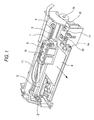
- Fig. 1 is a perspective view showing an embodiment of an ink jet printing device according to the present invention.
- Fig. 2 is a view showing an array of monochromatic and color printing heads on a carriage of the ink jet printing device.
- Fig. 3 is a view showing nozzle arrays on the monochromatic and color printing heads.
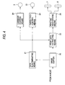
- Fig. 4 is a block diagram showing control means used in the ink jet printing device.
- Figs. 5(I) to 5(III) show the movements of the carriage and printable regions in printing modes, as viewed from the front side of the printing heads.
- Figs. 6(I) to 6(IV) are explanatory diagrams showing examples of printing by the ink jet printing device when it is operated in a normal print mode and an extension print mode.
- Fig. 1 shows a serial printing device according to an embodiment of the present invention, including a carriage 1.
- the carriage 1 is supported by a guide member 2, and coupled with a stepping motor 4 by way of a timing belt 3.
- the carriage 1 is reciprocally movable in parallel with a platen 5.
- a first ink jet printing head 7 for jetting black ink and a second ink jet printing head 8 for jetting color ink are mounted on the carriage 1 (Fig. 2). These printing heads are spaced apart from each other in the moving direction of the carriage 1, and the first printing head 7 is located closer to the home position (the right end in the figure).
- a black ink cartridge 9 and a color ink cartridge 10 are located above the first and the second ink jet printing heads 7 and 8, respectively.
- Reference numeral 11 designates a capping means, which is provided in a nonprinting region located closer to the home position.
- the capping means 11 includes capping members 12 and 13 for capping the nozzle-opening contained surfaces of the first and the second printing heads 7 and 8 in a sealing fashion. When the recovery of the jetting ability of the printing heads is required, these capping members 12 and 13 receive a negative pressure from a suction pump unit 14.
- Reference numeral 15 designates a paper feeding motor.
- the paper feeding motor 15 feeds a printing paper 6 line by line.
- it feeds the paper 6 in smaller increments, e.g., dot by dot.
- the operation of the paper feeding motor 15 is controlled by paper-feed control means 23 (Fig. 4), which is described in detail hereinafter.
- Fig. 3 shows arrays of nozzle openings on the first and the second printing heads 7 and 8 when those heads are viewed from the rear sides thereof.
- a plural number of series of nozzle openings are longitudinally arrayed on the printing head.
- four series of nozzle openings B1, B2, B3 and B4 are confined within a space defined by distance L (Fig. 2).
- the second printing head 8 for color printing three series of nozzle openings for shooting forth ink of three colors, yellow (Y), magenta (M) and cyan (C) are arrayed on the printing head.
- the three nozzle opening series Y, M and C for color printing are linearly extended in the moving direction of the carriage.
- the nozzle opening series B1 is located closest to the second printing head 8 for color printing.
- the nozzle openings of the series B1 are horizontally aligned with those of the nozzle opening series Y, M and C, respectively.
- the nozzle openings of the remaining nozzle opening series B2 to B4 are linearly arrayed at fixed pitches in the vertical direction (paper feeding direction) such that when horizontally viewed, the nozzle openings of those series B2 to B4 are located between the adjacent nozzle openings of the nozzle opening series B1.
- Such an arrangement of the nozzle opening series and their nozzle openings in the first printing head 7 for monochromatic printing achieves an intended resolution, e.g., 360 DPI, by one path motion for printing.
- the nozzle openings of the nozzle opening series Y, M and C are vertically arrayed every four nozzle openings of the first printing head 7 for monochromatic printing. In other words, those nozzle openings are arrayed so as to achieve the resolution that is 1/4 (90 DPI) of that of the first printing head 7.
- One line is printed by four path motions as the paper is fed in small increments, e.g., dot by dot.
- Fig. 4 is a block diagram showing an example of a print control unit incorporated into the serial printing device according to the present invention.
- an image buffer 20 stores image data received from a host computer.
- Data discriminating means 21 receives print data and discriminates the type of the received print data, viz., the print data to be printed for a region (denoted as A in Fig. 6) where monochromatic printing is performed or the print data to be printed for another region (denoted as M in Fig. 6) that is extended from the normal printing region A.
- the operation mode of the printing for region A is referred to as a normal print mode.
- the operation mode of the printing for region M is referred to as an extension print mode.
- a graphic printing process is an example of the printing process carried out in the extension print mode.
- the print data extracting means 22 extracts print data from the image buffer 20, and transfers it to all of the dot forming elements.
- the print data extracting means 22 extracts the print data, which corresponds to the nozzle opening series B1 furthest from the printing region of the first printing head 7, from the image buffer 20, and transfers the image data to the nozzle opening series B1.
- the paper-feed control means 23 operates in the following ways. In the normal print mode, when the printing of one path is completed, the paper-feed control means 23 feeds a printing paper by one line. In the extension print mode, when the printing of one path is completed, the control means 23 feeds the paper by a smaller increment, e.g., one dot, in connection with the pitch of the arrayed nozzle openings of the nozzle opening series B1.
- the carriage control means 24 moves the carriage 1 from a home position HP to the normal printing region A.
- the carriage 1 is first accelerated (approach run La) from the home position HP, moved at a constant speed in the normal printing region A, decelerated at the position where the normal printing region A terminates, and stopped at an end point E1.
- the carriage 1 In the extension print mode, the carriage 1 is accelerated (approach run La) as in the normal print mode, and moved at a constant speed so as to allow at least the nozzle opening series B1 to print an image in an extension printing region M.
- reference numeral 25 designates a printing head driving means for driving the printing heads 7 and 8 on the basis of the data derived from the image buffer 20.
- serial printing device thus constructed will be described with reference to Fig. 5.
- a monochromatic printing operation of the printing device is described.
- Print data outputted from the host computer arrives at the image buffer 20.
- the print data is developed into bit map data in the buffer.
- the data discriminating means 21 checks to see whether the print data that is developed in the image buffer 20 contains the data to be printed in the extension printing region M, which is located on the right side of the printing paper.
- the print data extracting means 22 reads the print data out of the image buffer 20 while making the data correspond to the nozzle opening series B1 to B4 of the first printing head 7.
- the carriage control means 24 accelerates the carriage 1, and when the speed of the carriage 1 reaches a constant speed, the print data extracting means 22 outputs to the printing head to start the printing operation.
- the carriage control means 24 decelerates the carriage 1 and stops it at the end point E1. In this way, the printing operation of one line is performed.
- the paper-feed control means 23 drives the paper feeding motor 15 so as to feed the printing paper by one line.
- the printing operation is performed for the normal printing region A in the normal print mode, and is brought to an end.
- the carriage 1 is decelerated and stops at the end point E1.
- the print data extracting means 22 extracts only the print data corresponding to the first nozzle opening series B1 that is located furthest from the printing region of the first printing head 7, while the carriage control means 24 turns the movement of the carriage 1 at the end point E1 in the opposite direction, and accelerates the carriage 1 to move it toward the printing paper.
- a distance for acceleration of the nozzle opening series B1 of the first printing head 7 to the printing paper is longer than that of the nozzle opening series B4 located at the left end by the distance L between the nozzle opening series B1 and B4 (Fig. 2). Therefore, when the nozzle opening series B1 reaches the end of the paper, the speed of the carriage 1 has reached the constant speed for printing.
- the extracted print data is outputted to the nozzle opening series B1. Then, the printing is performed, and the image is printed in a state that the lines of the dot forming elements arrayed at the pitch, which is equal to the pitch of the arrayed nozzle openings of the nozzle opening series B1, are printed. These printed lines are the first, fifth, ninth, thirteenth, ... lines in this instance (Fig. 6(I)).
- the carriage control means 24 decelerates the carriage 1 and stops it at a preset position. Then, the carriage control means 24 moves the carriage 1 to the end point E1 again and the paper-feed control means 23 feeds the paper by one dot.
- the print data for the lines which are shifted from the lines printed in the previous printing operation i.e., the second, sixth, tenth, fourteenth, ... lines
- the carriage 1 is moved again toward the home position HP as in the previous printing operation. When it reaches the left end of the paper, the printing operation starts, to thereby print dots under the line previously printed (Fig. 6(II)).
- Such a printing operation is repeated a plural number of times, e.g., two times in the present embodiment, to thereby print the third, seventh, eleventh, fifteenth, ... lines (Fig. 6(III)), and the fourth, eighth, twelfth, ... lines (Fig. 6(IV)).
- the printing for the paper area corresponding to the width of one line (when viewed in the paper feeding direction) in the normal print mode is completed.
- the print control unit receives print data from the host computer and executes the printing in the paper feed direction by repeating the sequence of the printing operation as mentioned above.
- the extension printing region M adjoining the normal printing region A may be used as a printing region for the line numbers in a text print. Accordingly, the line numbers may be printed in the right margin of the text without using the print region (region A) for the text.
- the second printing head 8 is located closer to the end point E1 than the normal printing region A, and the second printing head 8 can move at a constant speed over the entire width of the paper.
- normal printing can occur in region P because the acceleration/deceleration distance La can be subtracted from the distance to the end point E1. Therefore, in a color printer which uses a color printing head for the second printing head 8, a color scale, such as color samples, may be printed in the margin of the paper outside the normal printing region A.
- the nozzle opening series B1 which is used in the extension print mode, contains the nozzle openings for printing the top line of the lines to be printed. Consequently, there is no need for reverse feeding of the paper when the paper is fed in small increments. Backlash, which is caused by reverse feeding, is therefore eliminated. The resultant print is free from banding caused by displacement of the head in the paper feeding direction.
- the first printing head 7 for monochromatic printing is used for extension printing. Accordingly, printing is limited to the extension printing region M shown in Fig. 5.
- the moving distance of the carriage 1 is selected so as to print a color image over the entire width of the paper in the normal print mode. Therefore, by using the three nozzle opening series Y, M and C of the second printing head 8 in place of the first printing head 7, it is possible to print in the entire region P including the region La.
- the print data extracting means 22 extracts the print data corresponding to the nozzle opening series Y of the second printing head 8, and the carriage control means 24 reverses the carriage 1 in its moving direction and accelerates it toward the paper.
- the print data extracted for the nozzle opening series Y is outputted to the nozzle opening series Y.
- the same data is also outputted to the remaining nozzle opening series M and C at preset time lags, successively.
- ink of yellow, cyan and magenta land on the printing paper along the same scan line in a superposed fashion (Fig. 5(III)).
- An image is printed in a state that only the first, fifth, ninth, thirteenth, ... lines are colored with the composite ink, or are not printed.
- the carriage control means 24 decelerates the carriage 1 and stops it at a preset position. Then, the carriage control means 24 moves the carriage 1 to the end point E1 again, and the paper-feed control means 23 feeds the paper by one dot.
- the print data for the nozzle opening series Y is extracted by the print data extracting means 22, and only the second, sixth, tenth, fourteenth, ... lines, which are shifted from the lines printed in the previous printing, are colored with the composite ink or not printed.
- the printing for the region P is repeated while the scan line is shifted dot by dot by feeding the printing paper in small increments.
- an image may be printed with a color other than black by limiting the number of the nozzle opening series used for printing to 1 or 2 color nozzle opening series. If the line numbers, which are printed separately from the text, are printed with a color other than black, the printed line numbers are more easily seen and distinctly discriminated from the text.
- a color scale, such as color samples, may be printed in the region P.
- Printing paper which is slightly larger than normal may be used for printing if the moving distance of the carriage in the extension print region is reduced, or if the paper transporting path is correspondingly selected.
- the paper is fed in small increments only when printing in the extension print region.
- the data discriminating means 21 determines that the data to be printed in the extension print mode is contained in the print data for one line, the same printing method as the extension printing method may be applied in printing the entire line including the normal printing region A.
- An entire page can be checked to determine whether or not data is to be printed for the extension print region, and if such data is detected, the entire page may be printed by an intermittent printing method using the nozzle opening series B1 or the nozzle opening series Y, M and C, the printing method being based on the interlacing printing technique disclosed, for example, in US-Patent No. 4,198,642
- the storage capacity of the memory contained in the printing device is insufficient for storing print data of an entire page.
- a memory area that is large enough to store the print data of one page may be provided in the memory of the host computer, and a data check function can be incorporated into the print driver contained in the host computer. Only the data of the print paths to be printed, when required, are outputted to the printing device through a communication line.
- the data discriminating means 21 (Fig. 4) can be located else where.
- the expansion print region is located in the right margin on the printing paper. If required, it may be located in the left margin. In this case, the first printing head 7 and the second printing head 8 are reversed in position. In other words, in Fig. 2, the first printing head 7 is located on the right side, and the second printing head 8 is located on the left side.
- serial printing device which is constructed as described above effectively uses the space between the dot forming element series, and reduces the moving distance of the carriage so as to create an increased printing area, which is larger than the printing area for normal printing.
Landscapes
- Ink Jet (AREA)
- Dot-Matrix Printers And Others (AREA)
- Character Spaces And Line Spaces In Printers (AREA)
Claims (10)
- Seriendruckvorrichtung enthaltend:dadurch gekennzeichnet,einen Seriendruckkopf (7) mit einer Mehrzahl von Punktbildungselementreihen (B1, B2, B3, B4), die jeweils eine Mehrzahl von Punktbildungselementen aufweisen, die linear in festen Abständen in einer Druckmediumvorschubrichtung angeordnet sind, undeinen Schlitten (1), auf welchem der Seriendruckkopf (7) angebracht ist,daß ein Steuermittel vorgesehen ist zur Steuerung eines ersten Druckverfahrens, bei dem erste Druckdaten an den Seriendruckkopf (7) zum Drucken eines Bildes einer Zeile in einem Druckpfad ausgegeben werden, und zur Steuerung eines zweiten Druckverfahrens, bei dem zweite Druckdaten an eine der Punktbildungselementreihen (B1) abgegeben werden, die sich am nächsten zu einem Ende des Seriendruckkopfes in Druckmediumbreitenrichtung befinden, und ein Bild in einer Mehrzahl von Druckpfaden gedruckt wird, während ein Druckmedium in kleinen Schritten von weniger als einer Zeile vorgeschoben wird, jedesmal wenn die Bewegung eines jeden Druckpfades vollendet ist, undDatendiskriminierungsmittel (21) vorgesehen sind zur Diskriminierung der ersten oder der zweiten Druckdaten und zur Auswahl des entsprechend diskriminierten Druckverfahrens.
- Seriendruckvorrichtung gemäß Anspruch 1, bei dem die eine der Punktbildungselementreihen (B1), die sich am nächsten zu einem Ende des Seriendruckkopfes (7) befindet, ein Punktbildungselement aufweist, das entlang einer obersten Abtastzeile jeder Zeile in dem ersten Druckverfahren angeordnet ist.
- Seriendruckvorrichtung enthaltend:einen ersten Seriendruckkopf (7) mit einer Mehrzahl von Punktbildungselementreihen (B1, B2, B3, B4), die jeweils eine Mehrzahl von Punktbildungselementen aufweisen, die linear in festen Abständen in einer Druckmediumvorschubrichtung angeordnet sind, wobei die Mehrzahl von Punktbildungselementreihen (B1, B2, B3, B4) in einer Druckmediumbreitenrichtung angeordnet ist,einen zweiten Seriendruckkopf (8), der eine Mehrzahl von Punktbildungselementreihen (Y, M, C) aufweist, wobei die Mehrzahl von Punktbildungselementreihen (Y, M, C) Seite an Seite in Druckmediumbreitenrichtung angeordnet und in Druckmediumbreitenrichtung mit den Punktbildungselementen einer der Mehrzahl von Punktbildungselementreihen (B1, B2, B3, B4) des ersten Seriendruckkopfs (7) ausgerichtet ist, undeinen Schlitten (1), auf welchem der erste und der zweite Seriendruckkopf (7,8) angebracht sind, dadurch gekennzeichnet, daß ein Steuermittel (23) vorgesehen ist zur Steuerung eines ersten Druckverfahrens, bei dem erste Druckdaten an den ersten Seriendruckkopf (7) zum Drucken eines Bildes einer Zeile in einer Druckbahn ausgegeben werden, und zur Steuerung eines zweiten Druckverfahrens, bei dem zweite Druckdaten an den zweiten Seriendruckkopf (8) ausgegeben werden, und ein Bild in einer Mehrzahl von Druckpfaden gedruckt wird, indem ein Druckmedium in kleinen Schritten von weniger als einer Zeile in Druckmediumvorschubrichtung vorgeschoben wird, während jeder der Mehrzahl von Druckpfaden vollendet wird, undDatendiskriminierungsmittel (21) vorgesehen sind zur Diskriminierung der ersten oder der zweiten Druckdaten und zur Auswahl des entsprechend diskriminierten Druckverfahrens, unddie Mehrzahl von Punktbildungselementreihen (B1, B2, B3, B4) gegeneinander in Druckmediumvorschubrichtung versetzt ist.
- Seriendruckvorrichtung gemäß einem der vorhergehenden Ansprüche, bei dem der Schlitten (1) in Druckmediumbreitenrichtung hin- und herbewegbar ist.
- Seriendruckvorrichtung gemäß einem der vorhergehenden Ansprüche, bei dem in dem ersten Druckverfahren Druckdaten ausgegeben werden, wenn eine Bewegungsgeschwindigkeit des Schlittens (1) eine konstante Druckgeschwindigkeit erreicht.
- Seriendruckvorrichtung gemäß einem der Ansprüche 3 bis 5, bei dem die Farben von mittels der Punktbildungselmente des zweiten Seriendruckkopfes (8) gebildeten Punkten sich von einer Farbe von mittels der Punktbildungselemente des ersten Seriendruckkopfs (7) gebildeten Punkten unterscheidet.
- Seriendruckvorrichtung gemäß einem der Ansprüche 3 bis 6, bei dem die Mehrzahl von Punktbildungselementreihen (Y, M, C) des zweiten Seriendruckkopfs (8) mit einer obersten Abtastzeile von jeder Zeile in dem ersten Druckverfahren ausgerichtet ist.
- Seriendruckvorrichtung gemäß einem der Ansprüche 3 bis 7, bei dem der zweite Seriendruckkopf (8) ein Tintenstrahldruckkopf zum Ausstoß von Tintentröpfchen in den Farben Gelb, Magenta und Zyan ist.
- Seriendruckvorrichtung gemäß einem der vorhergehenden Ansprüche, bei dem, wenn die Druckdaten einem erweiterten Druckbereich (M) außerhalb eines normalen Textdruckbereichs (A) entsprechen, das Steuermittel (23) das zweite Druckverfahren derart steuert, daß das zweite Druckverfahren nur in dem erweiterten Druckbereich (M) durchgeführt wird.
- Seriendruckvorrichtung gemäß einem der Ansprüche 1 bis 8, bei dem, wenn die Druckdaten einem erweiterten Druckbereich (M) außerhalb eines normalen Textdruckbereichs (A) entsprechen, das Steuermittel (23) das zweite Druckverfahren derart steuert, daß das zweite Druckverfahren zum Drucken einer gesamten Zeile durchgeführt wird.
Applications Claiming Priority (6)
| Application Number | Priority Date | Filing Date | Title |
|---|---|---|---|
| JP37601/95 | 1995-02-02 | ||
| JP3760195 | 1995-02-02 | ||
| JP3760195 | 1995-02-02 | ||
| JP35165495A JP3305182B2 (ja) | 1995-02-02 | 1995-12-26 | シリアル記録装置 |
| JP35165495 | 1995-12-26 | ||
| JP351654/95 | 1995-12-26 |
Publications (2)
| Publication Number | Publication Date |
|---|---|
| EP0724962A1 EP0724962A1 (de) | 1996-08-07 |
| EP0724962B1 true EP0724962B1 (de) | 2000-06-14 |
Family
ID=26376737
Family Applications (1)
| Application Number | Title | Priority Date | Filing Date |
|---|---|---|---|
| EP96101514A Expired - Lifetime EP0724962B1 (de) | 1995-02-02 | 1996-02-02 | Seriendrucker |
Country Status (4)
| Country | Link |
|---|---|
| US (1) | US5683188A (de) |
| EP (1) | EP0724962B1 (de) |
| JP (1) | JP3305182B2 (de) |
| DE (1) | DE69608823T2 (de) |
Families Citing this family (27)
| Publication number | Priority date | Publication date | Assignee | Title |
|---|---|---|---|---|
| DE69717203T2 (de) * | 1996-07-30 | 2003-07-10 | Canon K.K., Tokio/Tokyo | Aufzeichnungsgerät und Gradationsaufzeichnungsverfahren in geteilten oder überlappenden Gebieten des Aufzeichnungsmediums |
| JP3245360B2 (ja) * | 1996-07-30 | 2002-01-15 | キヤノン株式会社 | 画像記録装置 |
| KR0184566B1 (ko) * | 1996-09-19 | 1999-05-15 | 삼성전자주식회사 | 시리얼 프린터의 드래프트 인쇄시 세로줄 정렬방법 |
| JPH10193658A (ja) * | 1996-11-14 | 1998-07-28 | Sanyo Electric Co Ltd | 分割シール記録紙を用いる印写方法および印写装置 |
| JPH10278317A (ja) | 1997-02-04 | 1998-10-20 | Seiko Epson Corp | インクジェット式記録装置 |
| EP0893265A3 (de) * | 1997-07-25 | 2000-05-10 | Seiko Epson Corporation | Farbstrahldruckvorrichtung |
| US6050674A (en) * | 1997-07-28 | 2000-04-18 | Canon Kabushiki Kaisha | Multi-head printer with wide printing mode |
| US6373593B1 (en) * | 1998-05-04 | 2002-04-16 | Canon Kabushiki Kaisha | Printer which accommodates carriage speed non-uniformities |
| US6322197B1 (en) * | 1998-08-27 | 2001-11-27 | Canon Kabushiki Kaisha | Printing method and apparatus |
| US6404507B1 (en) * | 1999-04-14 | 2002-06-11 | Canon Kabushiki Kaisha | Printer carriage control |
| US6644801B2 (en) * | 1999-12-27 | 2003-11-11 | Canon Kabushiki Kaisha | Ink jet recording apparatus |
| US6902252B1 (en) | 2000-08-16 | 2005-06-07 | Hewlett-Packard Development Company, L.P. | Fluid ejection device with staggered ink drop generators |
| US6406127B1 (en) * | 2000-11-17 | 2002-06-18 | Xerox Corporation | High productivity/multipass/ink printing system and method |
| US6425653B1 (en) | 2000-12-07 | 2002-07-30 | Xerox Corporation | Single pass printing of text among interleaved printing of non-text material |
| US6478404B2 (en) * | 2001-01-30 | 2002-11-12 | Hewlett-Packard Company | Ink jet printhead |
| JP3762228B2 (ja) * | 2001-01-31 | 2006-04-05 | キヤノン株式会社 | 記録装置および記録方法 |
| WO2002078957A1 (fr) * | 2001-03-28 | 2002-10-10 | Seiko Epson Corporation | Enregistreur a jet d'encre et tete d'enregistreur |
| EP1387224A3 (de) * | 2002-08-02 | 2011-11-16 | Eastman Kodak Company | Schmelzfixierelement, Vorrichtung und Verfahren zur elektrostatographischer Reproduktion |
| US7549718B2 (en) * | 2004-05-27 | 2009-06-23 | Silverbrook Research Pty Ltd | Printhead module having operation controllable on basis of thermal sensors |
| US7484831B2 (en) * | 2004-05-27 | 2009-02-03 | Silverbrook Research Pty Ltd | Printhead module having horizontally grouped firing order |
| US20060132516A1 (en) * | 2004-05-27 | 2006-06-22 | Walmsley Simon R | Printer controller for causing expulsion of ink from nozzles in groups, alternately, starting at outside nozzles of each group |
| US20060164462A1 (en) * | 2004-05-27 | 2006-07-27 | Silverbrook Research Pty Ltd | Print controller for supplying data to a printhead comprising different printhead modules |
| US7328956B2 (en) * | 2004-05-27 | 2008-02-12 | Silverbrook Research Pty Ltd | Printer comprising a printhead and at least two printer controllers connected to a common input of the printhead |
| US7427117B2 (en) | 2004-05-27 | 2008-09-23 | Silverbrook Research Pty Ltd | Method of expelling ink from nozzles in groups, alternately, starting at outside nozzles of each group |
| US20090195810A1 (en) * | 2008-02-04 | 2009-08-06 | Xerox Corporation | Printer driver apparatus and methods |
| JP2012223931A (ja) * | 2011-04-18 | 2012-11-15 | Seiko Epson Corp | 画像処理装置、印刷装置、画像処理方法および画像処理プログラム |
| JP6260110B2 (ja) * | 2013-05-17 | 2018-01-17 | ブラザー工業株式会社 | 液体吐出装置 |
Family Cites Families (10)
| Publication number | Priority date | Publication date | Assignee | Title |
|---|---|---|---|---|
| JPS5971865A (ja) * | 1982-10-19 | 1984-04-23 | Nec Corp | カラ−インクジエツトプリンタ |
| JPH0681245B2 (ja) * | 1983-07-06 | 1994-10-12 | キヤノン株式会社 | 画像記録装置 |
| JPH0755560B2 (ja) * | 1985-05-09 | 1995-06-14 | シャープ株式会社 | インクジェットプリンタ |
| US4728968A (en) * | 1985-08-30 | 1988-03-01 | Siemens Aktiengesellschaft | Arrangement of discharge openings in a printhead of a multi-color ink printer |
| JP2710943B2 (ja) * | 1988-02-26 | 1998-02-10 | キヤノン株式会社 | インクジェットプリンタ |
| US5075689A (en) * | 1989-05-31 | 1991-12-24 | Spectra, Inc. | Bidirectional hot melt ink jet printing |
| JPH06171084A (ja) * | 1992-02-07 | 1994-06-21 | Seiko Epson Corp | インクジェット記録ヘッド |
| US5512923A (en) * | 1992-09-30 | 1996-04-30 | Hewlett-Packard Company | Color variation control method for ink-jet printers |
| EP0610096B1 (de) * | 1993-02-05 | 2002-07-31 | Canon Kabushiki Kaisha | Farbstrahlaufzeichnungsgerät |
| US5455610A (en) * | 1993-05-19 | 1995-10-03 | Xerox Corporation | Color architecture for an ink jet printer with overlapping arrays of ejectors |
-
1995
- 1995-12-26 JP JP35165495A patent/JP3305182B2/ja not_active Expired - Fee Related
-
1996
- 1996-01-31 US US08/594,399 patent/US5683188A/en not_active Expired - Lifetime
- 1996-02-02 EP EP96101514A patent/EP0724962B1/de not_active Expired - Lifetime
- 1996-02-02 DE DE69608823T patent/DE69608823T2/de not_active Expired - Lifetime
Also Published As
| Publication number | Publication date |
|---|---|
| EP0724962A1 (de) | 1996-08-07 |
| JP3305182B2 (ja) | 2002-07-22 |
| DE69608823D1 (de) | 2000-07-20 |
| DE69608823T2 (de) | 2001-03-01 |
| US5683188A (en) | 1997-11-04 |
| JPH08267832A (ja) | 1996-10-15 |
Similar Documents
| Publication | Publication Date | Title |
|---|---|---|
| US5683188A (en) | Serial printing device having data discrimination | |
| EP0595650B1 (de) | Vorrichtung und Verfahren zur mehrfarbigen Tintenstrahlaufzeichnung | |
| EP0822089B1 (de) | Aufzeichnungsapparat vom Shuttle-Typ | |
| EP1228880B1 (de) | Tintenstrahldruckvorrichtung und Tintenstrahldruckverfahren | |
| US7625065B2 (en) | Ink jet print head and ink jet printing apparatus | |
| US5598192A (en) | Thermal ink jet printhead with extended print capability | |
| EP1176021B1 (de) | Druckanordnung die Maskenmuster verwendet mit Auflösungen, die nicht ganzzahlige Vielfache voneinander sind | |
| EP0983855A2 (de) | Ersatz von Punkten zur Kompensierung fehlender Tintenstrahldüsen | |
| US6530647B2 (en) | Color ink-jet head | |
| CN1116177C (zh) | 打印系统 | |
| US5936645A (en) | Serial printing apparatus controlled by open loop control system | |
| US7758154B2 (en) | Inkjet printing apparatus and inkjet printing method | |
| US5619233A (en) | Bidirectional ink jet printing with head signature reduction | |
| EP1120261B1 (de) | Falschregistrierungskorrektur für das drucken in zwei richtungen mit vermindertem fehlereinfluss durch vertikales abtasten | |
| EP1192048B1 (de) | Druckverfahren mit einem tintenstrahldrucker unter verwendung von mehrfachen druckwagengeschwindigkeiten | |
| EP1525992B1 (de) | Druckvorrichtung | |
| AU690119B2 (en) | Recording apparatus | |
| US7252364B2 (en) | Ink jet printing apparatus and printing position setting method of the apparatus | |
| US6097409A (en) | Image recording apparatus | |
| EP0727757B1 (de) | Verfahren und Vorrichtung zum Drucken unter Verwendung von Punktverschiebung | |
| US6488356B1 (en) | Bidirectional color ink jet printing with head signature reduction | |
| JP3293707B2 (ja) | インクジェット記録装置 | |
| JP2004338215A (ja) | プリンタ | |
| JPH05138900A (ja) | 画像形成装置 | |
| JPH08281973A (ja) | インクジェット式カラープリンタ |
Legal Events
| Date | Code | Title | Description |
|---|---|---|---|
| PUAI | Public reference made under article 153(3) epc to a published international application that has entered the european phase |
Free format text: ORIGINAL CODE: 0009012 |
|
| AK | Designated contracting states |
Kind code of ref document: A1 Designated state(s): DE FR GB |
|
| 17P | Request for examination filed |
Effective date: 19960910 |
|
| 17Q | First examination report despatched |
Effective date: 19961025 |
|
| GRAG | Despatch of communication of intention to grant |
Free format text: ORIGINAL CODE: EPIDOS AGRA |
|
| GRAG | Despatch of communication of intention to grant |
Free format text: ORIGINAL CODE: EPIDOS AGRA |
|
| GRAH | Despatch of communication of intention to grant a patent |
Free format text: ORIGINAL CODE: EPIDOS IGRA |
|
| GRAH | Despatch of communication of intention to grant a patent |
Free format text: ORIGINAL CODE: EPIDOS IGRA |
|
| GRAA | (expected) grant |
Free format text: ORIGINAL CODE: 0009210 |
|
| AK | Designated contracting states |
Kind code of ref document: B1 Designated state(s): DE FR GB |
|
| REF | Corresponds to: |
Ref document number: 69608823 Country of ref document: DE Date of ref document: 20000720 |
|
| ET | Fr: translation filed | ||
| PLBE | No opposition filed within time limit |
Free format text: ORIGINAL CODE: 0009261 |
|
| STAA | Information on the status of an ep patent application or granted ep patent |
Free format text: STATUS: NO OPPOSITION FILED WITHIN TIME LIMIT |
|
| 26N | No opposition filed | ||
| REG | Reference to a national code |
Ref country code: GB Ref legal event code: IF02 |
|
| PGFP | Annual fee paid to national office [announced via postgrant information from national office to epo] |
Ref country code: FR Payment date: 20110218 Year of fee payment: 16 Ref country code: DE Payment date: 20110126 Year of fee payment: 16 |
|
| PGFP | Annual fee paid to national office [announced via postgrant information from national office to epo] |
Ref country code: GB Payment date: 20110209 Year of fee payment: 16 |
|
| GBPC | Gb: european patent ceased through non-payment of renewal fee |
Effective date: 20120202 |
|
| REG | Reference to a national code |
Ref country code: FR Ref legal event code: ST Effective date: 20121031 |
|
| REG | Reference to a national code |
Ref country code: DE Ref legal event code: R119 Ref document number: 69608823 Country of ref document: DE Effective date: 20120901 |
|
| PG25 | Lapsed in a contracting state [announced via postgrant information from national office to epo] |
Ref country code: FR Free format text: LAPSE BECAUSE OF NON-PAYMENT OF DUE FEES Effective date: 20120229 Ref country code: GB Free format text: LAPSE BECAUSE OF NON-PAYMENT OF DUE FEES Effective date: 20120202 |
|
| PG25 | Lapsed in a contracting state [announced via postgrant information from national office to epo] |
Ref country code: DE Free format text: LAPSE BECAUSE OF NON-PAYMENT OF DUE FEES Effective date: 20120901 |