EP0724976A1 - Gefedertes Fahrwerk für eine landwirtschaftliche Maschine - Google Patents
Gefedertes Fahrwerk für eine landwirtschaftliche Maschine Download PDFInfo
- Publication number
- EP0724976A1 EP0724976A1 EP96490008A EP96490008A EP0724976A1 EP 0724976 A1 EP0724976 A1 EP 0724976A1 EP 96490008 A EP96490008 A EP 96490008A EP 96490008 A EP96490008 A EP 96490008A EP 0724976 A1 EP0724976 A1 EP 0724976A1
- Authority
- EP
- European Patent Office
- Prior art keywords
- frame
- axle
- chassis
- axis
- wheels
- Prior art date
- Legal status (The legal status is an assumption and is not a legal conclusion. Google has not performed a legal analysis and makes no representation as to the accuracy of the status listed.)
- Granted
Links
- 239000000725 suspension Substances 0.000 claims abstract description 18
- 238000005096 rolling process Methods 0.000 claims abstract description 9
- 230000035939 shock Effects 0.000 claims description 8
- 238000005507 spraying Methods 0.000 claims description 6
- 239000006096 absorbing agent Substances 0.000 claims description 2
- 239000007921 spray Substances 0.000 description 10
- 239000007788 liquid Substances 0.000 description 3
- 230000010355 oscillation Effects 0.000 description 3
- 238000010521 absorption reaction Methods 0.000 description 1
- 230000006978 adaptation Effects 0.000 description 1
- 230000003321 amplification Effects 0.000 description 1
- 230000006835 compression Effects 0.000 description 1
- 238000007906 compression Methods 0.000 description 1
- 230000001627 detrimental effect Effects 0.000 description 1
- 239000003337 fertilizer Substances 0.000 description 1
- 238000004519 manufacturing process Methods 0.000 description 1
- 238000003199 nucleic acid amplification method Methods 0.000 description 1
- 230000001681 protective effect Effects 0.000 description 1
Images

Classifications
-
- A—HUMAN NECESSITIES
- A01—AGRICULTURE; FORESTRY; ANIMAL HUSBANDRY; HUNTING; TRAPPING; FISHING
- A01M—CATCHING, TRAPPING OR SCARING OF ANIMALS; APPARATUS FOR THE DESTRUCTION OF NOXIOUS ANIMALS OR NOXIOUS PLANTS
- A01M7/00—Special adaptations or arrangements of liquid-spraying apparatus for purposes covered by this subclass
- A01M7/0003—Atomisers or mist blowers
- A01M7/0014—Field atomisers, e.g. orchard atomisers, self-propelled, drawn or tractor-mounted
-
- B—PERFORMING OPERATIONS; TRANSPORTING
- B60—VEHICLES IN GENERAL
- B60G—VEHICLE SUSPENSION ARRANGEMENTS
- B60G9/00—Resilient suspensions of a rigid axle or axle housing for two or more wheels
- B60G9/02—Resilient suspensions of a rigid axle or axle housing for two or more wheels the axle or housing being pivotally mounted on the vehicle, e.g. the pivotal axis being parallel to the longitudinal axis of the vehicle
- B60G9/027—Resilient suspensions of a rigid axle or axle housing for two or more wheels the axle or housing being pivotally mounted on the vehicle, e.g. the pivotal axis being parallel to the longitudinal axis of the vehicle the axle having either a triangular, a "T" or "U" shape and being directly articulated with the chassis only by its middle apex, e.g. De Dion suspension
Definitions
- the present invention relates to a suspended chassis for agricultural machinery, and more particularly finds its application in the manufacture of agricultural machinery which are equipped with ramps, such as for example agricultural vehicles used to spray a liquid. It also relates to an agricultural machine equipped with such a chassis.
- the spray bars are articulated relative to the chassis of the machine, so that in the folded state, they are positioned in the axis of advance of the chassis, and that at deployed state, they are positioned transversely and cantilevered relative to the chassis.
- it is advantageously folded down along the chassis, so as to reduce the size of the agricultural machine, which facilitates movement especially on the road .
- the spraying booms when one wishes to implement the spraying booms, they are deployed, which makes it possible to spray in a single pass over a very large width.
- the object of the present invention is to provide a suspended chassis for agricultural machinery, which is of simple design and which makes it possible to increase the speeds of movement of the machine, while retaining maximum stability transverse to the chassis.
- the chassis of the invention comprises, in a known manner, in particular by English patent application GB.2.035.233, a frame which is supported at its two end parts respectively by a first axle connecting two wheels between them, and by a rolling support, the first axle being rigidly fixed to a first lifting beam mounted freely in rotation on the frame, around an axis which is transverse to the direction of advance of the frame and which is offset upwards by relative to the axis of the wheels, and first suspension means being interposed between the lifter and the frame.
- the axis of rotation of the first lifter is offset towards the front of the frame relative to the axis of the wheels and the part of the frame opposite to the first axle is designed to be able to pivot freely relative to its support, around a central axis and parallel to the direction of advancement of the frame.
- the first axle of the chassis of the invention not being free to rotate along the axis of advance of the chassis, it constitutes a rigid axle to roll.
- the wheels retract towards the rear of the chassis, according to a movement damped by the suspension means of the spreader.
- the shocks in the direction of advancement of the machine are perfectly absorbed and the frame of the chassis retains a constant ground clearance at least at the level of the first axle.
- the pivoting of the part of the frame of the chassis which is opposite to the first axle advantageously makes it possible, in combination with the use of a first rigid axle to roll, keep the chassis frame in a plane parallel to the ground, regardless of the oscillating movement likely to be taken along the axis of advancement of the machine, by the rolling support in contact with the ground. Thanks to the chassis of the invention, a maximum transverse stability is therefore obtained at the level of the first axle.
- the spraying booms will be fixed to the chassis at the level of the first rigid rolling axle, which may be either at the front either at the rear in the direction of advancement of the machine.
- the chassis is provided for a towable agricultural machine.
- it comprises a single rear axle
- the chassis frame is equipped, opposite this rear axle, with a central attachment pivotally mounted in the direction of advancement of the chassis.
- the chassis of the invention is provided for a self-propelled agricultural machine.
- the rolling support is a second axle which connects two wheels together, and which is mounted for free rotation on a second spreader, about a central axis and parallel to the direction of advance of the frame;
- the second lifter is mounted to rotate freely on the frame, about an axis which is transverse to the direction of advancement of the frame, and which is offset upwards and forwards of the wheels of the second axle; and second suspension means are interposed between the frame and the second lifter.
- the rotation of the second spreader makes it possible to absorb the shocks in the direction of advance of the machine.
- the chassis frame therefore retains a constant ground clearance over its entire length.
- the free rotation of the second axle makes it possible to obtain a good adaptation of the chassis to the terrain, without modifying the horizontality of the chassis frame and without excessive stress on the chassis.
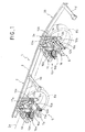
- FIG. 1 a suspended chassis 1 according to the invention and more particularly suitable for a self-propelled sprayer vehicle.
- This frame 1 comprises a frame 2, central axis 2a, supported at both end portions by two undercarriages front and rear respectively referenced 5 and 6.
- the frame 2 comprises two longitudinal longitudinal sections 3 parallel, made integral by means of three crosspieces 4 a , 4 b , 4 c .
- the front end 3 a of each profile 3 is further extended by a short profile 3 b slightly inclined downwards.
- Each short section 3b will for example be welded to the front end 3 a of a section 3.
- the two short sections 3 b are also kept apart in a parallel position by means of a cross member 4 d .
- the main bodies (not shown) of the sprayer vehicle are divided as follows relative to the frame 2 of the frame 1.
- the motor is positioned in front of the short sections 3b.
- the cockpit is positioned at the level of the two crosspieces 4 b and 4 c .
- the tank containing the liquid to be sprayed is placed at the rear, on the crosspieces 4 a and 4 b .
- the spray bars are attached to the rear undercarriage 5.
- the rear undercarriage 5 comprises an axle 7a which connects two wheels 8a, rotatably supported by the wheel carrier 9 a; one of these two wheels 8a is shown in Figure 1.
- This rear axle 7a is rigidly attached to a lifting beam 10a, pivotally mounted relative to the frame 2 of the frame 1.
- the suspension means 15 are interposed between a the rear spreader 10 a and the frame 2.
- the lifter 10 to be pivoted about two axes 12a, respectively integral with two triangles 13a themselves fixed vis-à-vis one from the other on each profile 3 of the frame 2.
- the two axes 12 a are located in the extension of one another, in a direction transverse to the axis 2 a of the frame 2.
- the axle 7 a is rigidly fixed to the lifter 10 a by means of two arms 11 a acting as a lever arm relative to the two axes of rotation 12 a .
- the lifter 10 has comprises a central plate 14a which supports the suspension means 15 a and the lower face rests and is welded to axle 7 a. This central plate 14 acted as the lever arm relative to the two axes of rotation 12 a of the yoke 10 a.
- the suspension means 15 a consist, on the one hand, of a cylindrical compression spring with a round wire and with constant pitch 16 a , which is positioned behind the axle 7 a , and on the other hand, two shock absorbers 17 a placed on either side of the spring 16 a , substantially at the level of the axle 7 a .
- the undercarriage before 6 differs from the rear undercarriage 5 which has just been described primarily in that its front axle 7 b is not a rigid axle to roll, unlike the rear axle 7a, but is mounted freely in rotation on the front spreader 10 b , around an axis 11 b parallel to the axis 2 a of the frame 2 and centered relative to the frame 2.
- FIG. 2 clearly shows that the axes of rotation 12b of the front spreader 10b are offset forward by a distance d 1 and upwards by a distance d 2 , relative to the axes of rotation 8c of the front wheels. 8b.
- frame 2 of the chassis therefore remains constantly in a plane parallel to the ground, shock absorption in the direction of advancement of the machine by the spreaders 10 to 10 b and the suspension means 15 a , 15 b also allowing the chassis to maintain a constant ground clearance, without amplification of the differences in ground level taken in a direction transverse to the direction of advance of the machine.
- the travel of the front axle 7 about the axis b 11 b is limited in amplitude by the plate 14 b of the yoke 10 b before.
- the maximum value of the angle ⁇ will therefore depend on the distance e between the plate 14b and the front axle 7b ( Figure 2), as well as on the width of the plate 14b .
- the distance between the two wheels of each undercarriage was 1.80m; the distances d 1 and d 2 were identical for the two front and rear axles and were respectively 300 and 400mm; the maximum value of the angles ⁇ and ⁇ was of the order of 20 °; the front and rear wheels had maximum travel in a vertical plane of 0.5m.
- the chassis may comprise only a single rear undercarriage 5.
- the connection between the chassis and the tractor vehicle will in this case be carried out by means of a fastener centered on the front part of the chassis frame, and which can pivot along an axis parallel to the axis of advance of the chassis.
- the chassis will preferably have the shape of an isosceles triangle, the base of which will be supported by the rear undercarriage.
- any other suspension means known to those skilled in the art. We can in particular replace the mechanical spring 16a by a pneumatic spring or bellows, or even by oil-pneumatic suspension cylinders.
Landscapes
- Life Sciences & Earth Sciences (AREA)
- Engineering & Computer Science (AREA)
- Insects & Arthropods (AREA)
- Pest Control & Pesticides (AREA)
- Wood Science & Technology (AREA)
- Zoology (AREA)
- Environmental Sciences (AREA)
- Mechanical Engineering (AREA)
- Catching Or Destruction (AREA)
- Vehicle Body Suspensions (AREA)
- Tires In General (AREA)
- Soil Working Implements (AREA)
Applications Claiming Priority (2)
| Application Number | Priority Date | Filing Date | Title |
|---|---|---|---|
| FR9501467 | 1995-02-03 | ||
| FR9501467A FR2730191B1 (fr) | 1995-02-03 | 1995-02-03 | Chassis suspendu pour engin agricole |
Publications (2)
| Publication Number | Publication Date |
|---|---|
| EP0724976A1 true EP0724976A1 (de) | 1996-08-07 |
| EP0724976B1 EP0724976B1 (de) | 1998-12-30 |
Family
ID=9475960
Family Applications (1)
| Application Number | Title | Priority Date | Filing Date |
|---|---|---|---|
| EP96490008A Expired - Lifetime EP0724976B1 (de) | 1995-02-03 | 1996-01-29 | Landwirtschaftliche Maschine mit gefederten Fahrwerk |
Country Status (4)
| Country | Link |
|---|---|
| EP (1) | EP0724976B1 (de) |
| AT (1) | ATE175156T1 (de) |
| DE (1) | DE69601232T2 (de) |
| FR (1) | FR2730191B1 (de) |
Cited By (1)
| Publication number | Priority date | Publication date | Assignee | Title |
|---|---|---|---|---|
| US9140398B2 (en) | 2010-04-02 | 2015-09-22 | Pentair Flow Technologies, Llc | Air aspiration device |
Families Citing this family (1)
| Publication number | Priority date | Publication date | Assignee | Title |
|---|---|---|---|---|
| ES2358499B1 (es) * | 2008-12-01 | 2012-02-06 | Amp Sprayers, S.L. | Perfeccionamientos en una máquina fumigadora agrícola. |
Citations (2)
| Publication number | Priority date | Publication date | Assignee | Title |
|---|---|---|---|---|
| GB2035233A (en) * | 1978-10-25 | 1980-06-18 | Willmot Ltd C & G | An agricultural spreading vehicle |
| FR2605966A1 (fr) * | 1986-11-04 | 1988-05-06 | Deboffles Regis | Vehicule automoteur destine a deplacer un outil allonge transversal |
Family Cites Families (1)
| Publication number | Priority date | Publication date | Assignee | Title |
|---|---|---|---|---|
| US4063361A (en) * | 1977-01-03 | 1977-12-20 | Westinghouse Air Brake Company | Power train for two-wheel tractor |
-
1995
- 1995-02-03 FR FR9501467A patent/FR2730191B1/fr not_active Expired - Fee Related
-
1996
- 1996-01-29 EP EP96490008A patent/EP0724976B1/de not_active Expired - Lifetime
- 1996-01-29 DE DE69601232T patent/DE69601232T2/de not_active Expired - Fee Related
- 1996-01-29 AT AT96490008T patent/ATE175156T1/de not_active IP Right Cessation
Patent Citations (2)
| Publication number | Priority date | Publication date | Assignee | Title |
|---|---|---|---|---|
| GB2035233A (en) * | 1978-10-25 | 1980-06-18 | Willmot Ltd C & G | An agricultural spreading vehicle |
| FR2605966A1 (fr) * | 1986-11-04 | 1988-05-06 | Deboffles Regis | Vehicule automoteur destine a deplacer un outil allonge transversal |
Cited By (2)
| Publication number | Priority date | Publication date | Assignee | Title |
|---|---|---|---|---|
| US9140398B2 (en) | 2010-04-02 | 2015-09-22 | Pentair Flow Technologies, Llc | Air aspiration device |
| US10018291B2 (en) | 2010-04-02 | 2018-07-10 | Pentair Flow Technologies, Llc | Air aspiration device |
Also Published As
| Publication number | Publication date |
|---|---|
| DE69601232D1 (de) | 1999-02-11 |
| FR2730191B1 (fr) | 1997-04-25 |
| FR2730191A1 (fr) | 1996-08-09 |
| ATE175156T1 (de) | 1999-01-15 |
| DE69601232T2 (de) | 1999-06-02 |
| EP0724976B1 (de) | 1998-12-30 |
Similar Documents
| Publication | Publication Date | Title |
|---|---|---|
| EP0238768B1 (de) | Lager- und Aufhängungsvorrichtung, verbunden mit dem Vorderrad eines Motorfahrrades | |
| EP3691959B1 (de) | Koppelbares automotives strassenfahrzeug mit kompakter lenkung und aufhängung | |
| FR2536345A1 (fr) | Suspension a triangles superposes et angle de chasse variable pour vehicules | |
| FR2578790A1 (fr) | Suspension de roue independante pour des roues directrices de vehicules automobiles | |
| EP0726198A2 (de) | Radaufhängung für ein Fahrzeug mit lenkbarem Vorderrad und Fahrzeug mit dieser Radaufhängung | |
| EP0945551B1 (de) | Kehrvorrichtung für Arbeitsfahrzeuge | |
| FR2539092A1 (fr) | Vehicule utilitaire automobile, notamment vehicule utilitaire agricole du genre tracteur | |
| FR2698825A1 (fr) | Dispositif de liaison entre les roues et le châssis d'un véhicule. | |
| EP0930183A1 (de) | Hinterradaufhängungsvorrichtung eines Kraftfahrzeuges | |
| EP0724976B1 (de) | Landwirtschaftliche Maschine mit gefederten Fahrwerk | |
| FR2580998A1 (fr) | Structure d'attelage entre un vehicule tracteur et un vehicule tracte | |
| FR2759245A1 (fr) | Machine de fenaison avec un dispositif d'appui au sol incluant au moins un balancier avec deux roues porteuses et un moyen pour deplacer ce balancier en vue du transport | |
| EP1111986B1 (de) | Fahrwerk für landwirtschaftliche maschine | |
| FR2605966A1 (fr) | Vehicule automoteur destine a deplacer un outil allonge transversal | |
| EP1670306B1 (de) | Heuerntemaschine mit einer transportaufhängungsvorrichtung | |
| EP3973754B1 (de) | Drehpflug vom typ aufsattelpflug mit wagen oder einzelrad | |
| EP0607721A1 (de) | Einziehfahrwerk eines Grossraumflugzeuges | |
| FR2758434A1 (fr) | Dispositif de suspension pour rampe de pulverisation agricole | |
| FR2882622A1 (fr) | Andaineuse a bras porte-rotors telescopiques | |
| FR2896949A1 (fr) | Rampe d'epandage de produits et appareil agricole d'epandage de produits | |
| FR2851120A1 (fr) | Charrue reversible semi-porte | |
| FR2752213A1 (fr) | Perfectionnement pour chassis de vehicule | |
| FR2551015A1 (fr) | Vehicule a train avant et chassis deportables lateralement relativement | |
| FR2662904A1 (fr) | Vehicule de traitement agricole. | |
| FR2747879A1 (fr) | Dispositif de montage des disques de coupe d'une machine pour le fauchage de l'herbe |
Legal Events
| Date | Code | Title | Description |
|---|---|---|---|
| PUAI | Public reference made under article 153(3) epc to a published international application that has entered the european phase |
Free format text: ORIGINAL CODE: 0009012 |
|
| AK | Designated contracting states |
Kind code of ref document: A1 Designated state(s): AT BE CH DE DK ES FR GB IE IT LI LU NL SE |
|
| 17P | Request for examination filed |
Effective date: 19970204 |
|
| 17Q | First examination report despatched |
Effective date: 19970515 |
|
| GRAG | Despatch of communication of intention to grant |
Free format text: ORIGINAL CODE: EPIDOS AGRA |
|
| GRAG | Despatch of communication of intention to grant |
Free format text: ORIGINAL CODE: EPIDOS AGRA |
|
| GRAH | Despatch of communication of intention to grant a patent |
Free format text: ORIGINAL CODE: EPIDOS IGRA |
|
| GRAH | Despatch of communication of intention to grant a patent |
Free format text: ORIGINAL CODE: EPIDOS IGRA |
|
| GRAA | (expected) grant |
Free format text: ORIGINAL CODE: 0009210 |
|
| AK | Designated contracting states |
Kind code of ref document: B1 Designated state(s): AT BE CH DE DK ES FR GB IE IT LI LU NL SE |
|
| PG25 | Lapsed in a contracting state [announced via postgrant information from national office to epo] |
Ref country code: ES Free format text: THE PATENT HAS BEEN ANNULLED BY A DECISION OF A NATIONAL AUTHORITY Effective date: 19981230 Ref country code: AT Free format text: LAPSE BECAUSE OF FAILURE TO SUBMIT A TRANSLATION OF THE DESCRIPTION OR TO PAY THE FEE WITHIN THE PRESCRIBED TIME-LIMIT Effective date: 19981230 |
|
| REF | Corresponds to: |
Ref document number: 175156 Country of ref document: AT Date of ref document: 19990115 Kind code of ref document: T |
|
| REG | Reference to a national code |
Ref country code: CH Ref legal event code: EP |
|
| GBT | Gb: translation of ep patent filed (gb section 77(6)(a)/1977) |
Effective date: 19981231 |
|
| PG25 | Lapsed in a contracting state [announced via postgrant information from national office to epo] |
Ref country code: LU Free format text: LAPSE BECAUSE OF NON-PAYMENT OF DUE FEES Effective date: 19990129 |
|
| REG | Reference to a national code |
Ref country code: IE Ref legal event code: FG4D Free format text: FRENCH |
|
| REF | Corresponds to: |
Ref document number: 69601232 Country of ref document: DE Date of ref document: 19990211 |
|
| PG25 | Lapsed in a contracting state [announced via postgrant information from national office to epo] |
Ref country code: SE Free format text: LAPSE BECAUSE OF FAILURE TO SUBMIT A TRANSLATION OF THE DESCRIPTION OR TO PAY THE FEE WITHIN THE PRESCRIBED TIME-LIMIT Effective date: 19990330 Ref country code: DK Free format text: LAPSE BECAUSE OF FAILURE TO SUBMIT A TRANSLATION OF THE DESCRIPTION OR TO PAY THE FEE WITHIN THE PRESCRIBED TIME-LIMIT Effective date: 19990330 |
|
| REG | Reference to a national code |
Ref country code: IE Ref legal event code: FD4D |
|
| PLBE | No opposition filed within time limit |
Free format text: ORIGINAL CODE: 0009261 |
|
| STAA | Information on the status of an ep patent application or granted ep patent |
Free format text: STATUS: NO OPPOSITION FILED WITHIN TIME LIMIT |
|
| 26N | No opposition filed | ||
| PG25 | Lapsed in a contracting state [announced via postgrant information from national office to epo] |
Ref country code: LI Free format text: LAPSE BECAUSE OF NON-PAYMENT OF DUE FEES Effective date: 20000131 Ref country code: CH Free format text: LAPSE BECAUSE OF NON-PAYMENT OF DUE FEES Effective date: 20000131 |
|
| REG | Reference to a national code |
Ref country code: CH Ref legal event code: PL |
|
| PGFP | Annual fee paid to national office [announced via postgrant information from national office to epo] |
Ref country code: DE Payment date: 20010116 Year of fee payment: 6 |
|
| PGFP | Annual fee paid to national office [announced via postgrant information from national office to epo] |
Ref country code: GB Payment date: 20010123 Year of fee payment: 6 |
|
| PGFP | Annual fee paid to national office [announced via postgrant information from national office to epo] |
Ref country code: BE Payment date: 20010209 Year of fee payment: 6 |
|
| PGFP | Annual fee paid to national office [announced via postgrant information from national office to epo] |
Ref country code: NL Payment date: 20011217 Year of fee payment: 7 |
|
| REG | Reference to a national code |
Ref country code: GB Ref legal event code: IF02 |
|
| PG25 | Lapsed in a contracting state [announced via postgrant information from national office to epo] |
Ref country code: GB Free format text: LAPSE BECAUSE OF NON-PAYMENT OF DUE FEES Effective date: 20020129 |
|
| PG25 | Lapsed in a contracting state [announced via postgrant information from national office to epo] |
Ref country code: BE Free format text: LAPSE BECAUSE OF NON-PAYMENT OF DUE FEES Effective date: 20020131 |
|
| BERE | Be: lapsed |
Owner name: S.A. HARDI-EVRARD Effective date: 20020131 |
|
| PG25 | Lapsed in a contracting state [announced via postgrant information from national office to epo] |
Ref country code: NL Free format text: LAPSE BECAUSE OF NON-PAYMENT OF DUE FEES Effective date: 20020801 Ref country code: DE Free format text: LAPSE BECAUSE OF NON-PAYMENT OF DUE FEES Effective date: 20020801 |
|
| GBPC | Gb: european patent ceased through non-payment of renewal fee |
Effective date: 20020129 |
|
| NLV4 | Nl: lapsed or anulled due to non-payment of the annual fee |
Effective date: 20020801 |
|
| PGFP | Annual fee paid to national office [announced via postgrant information from national office to epo] |
Ref country code: FR Payment date: 20050121 Year of fee payment: 10 |
|
| PG25 | Lapsed in a contracting state [announced via postgrant information from national office to epo] |
Ref country code: IT Free format text: LAPSE BECAUSE OF NON-PAYMENT OF DUE FEES Effective date: 20050129 |
|
| PG25 | Lapsed in a contracting state [announced via postgrant information from national office to epo] |
Ref country code: FR Free format text: LAPSE BECAUSE OF NON-PAYMENT OF DUE FEES Effective date: 20060131 |
|
| REG | Reference to a national code |
Ref country code: FR Ref legal event code: ST Effective date: 20060929 |