EP0725025A2 - Dispositif de guidage de feuilles pour machines à imprimer - Google Patents
Dispositif de guidage de feuilles pour machines à imprimer Download PDFInfo
- Publication number
- EP0725025A2 EP0725025A2 EP95119931A EP95119931A EP0725025A2 EP 0725025 A2 EP0725025 A2 EP 0725025A2 EP 95119931 A EP95119931 A EP 95119931A EP 95119931 A EP95119931 A EP 95119931A EP 0725025 A2 EP0725025 A2 EP 0725025A2
- Authority
- EP
- European Patent Office
- Prior art keywords
- nozzles
- air
- sheet
- guide surface
- printing
- Prior art date
- Legal status (The legal status is an assumption and is not a legal conclusion. Google has not performed a legal analysis and makes no representation as to the accuracy of the status listed.)
- Granted
Links
Images



Classifications
-
- B—PERFORMING OPERATIONS; TRANSPORTING
- B41—PRINTING; LINING MACHINES; TYPEWRITERS; STAMPS
- B41F—PRINTING MACHINES OR PRESSES
- B41F25/00—Devices for pressing sheets or webs against cylinders, e.g. for smoothing purposes
-
- B—PERFORMING OPERATIONS; TRANSPORTING
- B65—CONVEYING; PACKING; STORING; HANDLING THIN OR FILAMENTARY MATERIAL
- B65H—HANDLING THIN OR FILAMENTARY MATERIAL, e.g. SHEETS, WEBS, CABLES
- B65H29/00—Delivering or advancing articles from machines; Advancing articles to or into piles
- B65H29/02—Delivering or advancing articles from machines; Advancing articles to or into piles by mechanical grippers engaging the leading edge only of the articles
- B65H29/04—Delivering or advancing articles from machines; Advancing articles to or into piles by mechanical grippers engaging the leading edge only of the articles the grippers being carried by endless chains or bands
- B65H29/041—Delivering or advancing articles from machines; Advancing articles to or into piles by mechanical grippers engaging the leading edge only of the articles the grippers being carried by endless chains or bands and introducing into a pile
-
- B—PERFORMING OPERATIONS; TRANSPORTING
- B65—CONVEYING; PACKING; STORING; HANDLING THIN OR FILAMENTARY MATERIAL
- B65H—HANDLING THIN OR FILAMENTARY MATERIAL, e.g. SHEETS, WEBS, CABLES
- B65H29/00—Delivering or advancing articles from machines; Advancing articles to or into piles
- B65H29/02—Delivering or advancing articles from machines; Advancing articles to or into piles by mechanical grippers engaging the leading edge only of the articles
- B65H29/06—Delivering or advancing articles from machines; Advancing articles to or into piles by mechanical grippers engaging the leading edge only of the articles the grippers being carried by rotating members
-
- B—PERFORMING OPERATIONS; TRANSPORTING
- B65—CONVEYING; PACKING; STORING; HANDLING THIN OR FILAMENTARY MATERIAL
- B65H—HANDLING THIN OR FILAMENTARY MATERIAL, e.g. SHEETS, WEBS, CABLES
- B65H5/00—Feeding articles separated from piles; Feeding articles to machines
- B65H5/08—Feeding articles separated from piles; Feeding articles to machines by grippers, e.g. suction grippers
- B65H5/12—Revolving grippers, e.g. mounted on arms, frames or cylinders
-
- B—PERFORMING OPERATIONS; TRANSPORTING
- B65—CONVEYING; PACKING; STORING; HANDLING THIN OR FILAMENTARY MATERIAL
- B65H—HANDLING THIN OR FILAMENTARY MATERIAL, e.g. SHEETS, WEBS, CABLES
- B65H5/00—Feeding articles separated from piles; Feeding articles to machines
- B65H5/36—Article guides or smoothers, e.g. movable in operation
- B65H5/38—Article guides or smoothers, e.g. movable in operation immovable in operation
-
- B—PERFORMING OPERATIONS; TRANSPORTING
- B65—CONVEYING; PACKING; STORING; HANDLING THIN OR FILAMENTARY MATERIAL
- B65H—HANDLING THIN OR FILAMENTARY MATERIAL, e.g. SHEETS, WEBS, CABLES
- B65H2406/00—Means using fluid
- B65H2406/10—Means using fluid made only for exhausting gaseous medium
- B65H2406/11—Means using fluid made only for exhausting gaseous medium producing fluidised bed
-
- B—PERFORMING OPERATIONS; TRANSPORTING
- B65—CONVEYING; PACKING; STORING; HANDLING THIN OR FILAMENTARY MATERIAL
- B65H—HANDLING THIN OR FILAMENTARY MATERIAL, e.g. SHEETS, WEBS, CABLES
- B65H2406/00—Means using fluid
- B65H2406/30—Suction means
Definitions
- the invention relates to a sheet guide device for printing presses with guide surfaces for guiding the sheets, nozzles being provided in the guide surfaces, which can be acted upon by blown air or suction air.
- Such a sheet guiding device is known from DE 34 11 029 C2.
- this sheet guiding device an attempt is made to achieve a safe levitation of the sheet by making nozzles in the form of bores arranged vertically in the guide surfaces to make up a certain area of the guide surface.
- a disadvantage of this sheet guide device is that the nozzles are directed perpendicularly against the sheet to be guided. The air emerging from the nozzles bounces against the elbow, must be deflected by the latter with the application of forces and then flows out from the nozzle injection point radially at 360 ° in all directions. The impulse forces resulting from the deflection stimulate the bow to flutter.
- the air volumes flowing out of the nozzles after being deflected by the bend, are directed opposite the same air volumes of the neighboring nozzles. These opposing volumes collide and create areas with turbulence fields around the nozzles in which the nozzle air swirled and the kinetic energy of the jet air is consumed.
- the bow transport is disrupted due to the strong vortex formation.
- the bows are excited to flutter and vibrate, and the trailing edge in particular carries out lashing movements.
- the possibility of guiding a sheet printed on both sides without smearing is, if at all, only possible at a low machine speed and with considerable expenditure of time for the adjustment of the unstable blowing air free jets.
- the nozzles are pressurized with suction air and only generate a sheet guide under friction, which permits higher speeds of the printing press. If a sheet that is printed on both sides is now to be processed, areas on the back are necessary which must remain unprinted. The suction holes can become active in these areas. In between, it is then possible to prevent the printed sheets from smearing by blowing air, since the sheet holding forces are only generated by the absorbent areas.
- the invention has for its object to provide a sheet guiding device which avoids the disadvantages of the prior art and which ensures secure sheet travel with different substrates in face printing as well as in face and back printing with minimal makeready times.
- the advantage of the invention is that in the preferred mode, the blown air mode, the Due to the tangential air flow, the printing press is able to guide all substrates to be processed safely and without greasing. This is done by guiding the bends on an air flow, which, due to the tangential and rectified blowing direction of the nozzles, combines from several individual flows to form a main flow with a uniform flow direction. Due to its uniformity and uniformity, this flowing air cushion is able to guide the sheet without touching the sheet guide plates and thus without smearing, even in the event that both sides of the sheet are freshly printed.
- the areas or sections of the printing press which can be acted upon by suction air are preferably on all sheet-guiding lines Drums arranged, because in their centrifugal force area easily arcing disturbances occur.
- These drums are, for example, the feed drum adjoining the feeder, the transfer drums arranged between the printing units and the delivery drum with which the delivery takes over the sheets from the last printing unit. If additional transfer drums are installed in the machine, guide surfaces should also be installed there, which can be supplied with suction air in problematic areas.
- the arrangement of areas to which suction air can be applied is also possible in the delivery, for example in front of the sheet brake.
- the outlet areas of the guide surfaces of the sheet-guiding drums arranged upstream of the pressure cylinders are expediently designed so that suction air can be applied to them.
- These drums can be transfer drums which are arranged between the printing cylinders of the individual printing units.
- a plurality of sheet transport drums can be arranged between the printing cylinders.
- the sheet transport drum in front of the first printing cylinder is a feed drum that takes the sheet from the feeder and transports it to the printing cylinder.
- a further transport drum is provided in this area.
- a clean sheet guide is particularly important for the sheet-guiding drums located upstream of the printing cylinders, since the sheet's support on the printing cylinders and thus the quality of the print depend on this.
- the sheet Due to the action of suction air in these areas, the sheet experiences an additional advantageous automatic stabilization when it is transferred to the printing cylinder, which tightens the sheet and thereby serves to smoothly apply the sheet to the printing cylinder, thereby in particular adapting the printing press to the respective printing material in the In the case of touch-sensitive sheet backs is considerably simplified.
- the inlet areas of the guide surfaces of the sheet-guiding drums can also be optionally supplied with suction air. This is advantageous in the event that the machine comes to a standstill, for example due to an emergency stop or when the machine rotates slowly in jog mode. If such a machine standstill or slow forward rotation is the end of the sheet in the inlet area of the guide surface of a sheet-guiding drum, the rear end of the sheet is usually overhead, and the machine stop or a very slow forward rotation can cause the end of the sheet to fall and cause it to one Folding of the bow comes.
- the printing press only has to eject such sheets in the typing mode or they have to be removed until a new printing process can be carried out.
- a further development of the invention provides that the air supply takes place via axial fans which can be switched with respect to their direction of rotation. This allows the desired sections of the printing press to be switched over in a very simple manner.
- the air supply to the nozzles is preferably carried out by speed-controllable fans.
- the floating guide can be adjusted in the blowing mode, and in suction mode it is possible to adjust the frictional force of the sheet on the guide surfaces, which is adapted to the respective paper.
- there is the suction mode Possibility to extract just enough air that there is no contact between the bend and the baffle.
- an air supply can be provided in which individual areas or parts of the air supply take place via air supply boxes. At least a division of the guide surfaces into areas that are optionally supplied with blown or suction air and those areas of the guide surfaces that are preferably only operated in the blown air mode are required. Of course, a further subdivision is also possible, according to the degree to which the air exposure in a certain area of a guide surface has to take place.
- the advantage of the air supply boxes is that many nozzles can be supplied by means of an air supply element. For example, appropriately strong axial fans can be used for a larger number of nozzles. Due to the subdivision, it is nevertheless possible to apply air to the individual areas of the guide surfaces in a variable manner. It is therefore proposed to assign an axial fan to each blow box and to adapt the size of the air supply boxes to the air requirements of the respective areas.
- the guide surfaces have a different surface area with nozzles that is adapted to the respective air requirement. It is thus possible, for example, to provide the inlet and outlet areas of the guide surfaces with a higher area coverage and the guide zones in between with a lower area coverage. It is also possible to make the area coverage with nozzles largest in the middle of the sheet path and decreasing towards the edge. This is particularly expedient if the nozzles are slot nozzles directed towards the outside of the sheet path. It will then be in the middle of the The corresponding air flow is generated by the sheet path, which only needs to be maintained towards the edge, and therefore no longer requires the number of nozzles, as in the middle of the sheet path.
- all sections of the printing pressurized by air are set by a remote control.
- switching to suction mode using a remote control is time-saving if the machine is to be switched from reverse printing to straight printing or to operation with problematic papers. This can be done very easily by electronic control of the axial fans or other fans.
- Fig. 1 shows a schematic representation of a printing press with an embodiment of a sheet guide device according to the invention.
- the printing press only two printing units 20 and 20 'are shown for simple illustration; As a rule, however, such a printing press has four or more printing units.
- Each printing unit 20, 20 ' has a printing cylinder 8, 8', rubber cylinders 9, 9 'and a plate cylinder 10, 10' as well as inking units (not shown).
- a transfer drum 6 between the printing units 20 and 20 ' ensures that the sheets 4 to be printed are forwarded. If a printing press has several printing units, transfer drums 6 are always arranged between two printing units. Of course, it is also possible that several sheet transport drums are arranged instead of the one transfer drum 6.
- the sheet path 17 is shown, with the arrows 24 showing the direction of sheet travel.
- the sheets 4 are removed from a feeder stack 19 and passed on to a feed drum 5 by means of a feeder, not shown, which transfers the sheets 4 with their grippers to a printing cylinder 8 for printing. From the printing cylinder 8, the sheet 4 is taken over by the grippers 26 of the transfer drum 6 and fed to a further printing cylinder 8 ', so that further printing can take place.
- the pressure cylinder 8 transfers the sheet 4 to the delivery drum 7 of a delivery arm 21.
- the delivery drum 7 is the transfer drum for gripper bridges which are arranged on the delivery chain 22 and which transport the transferred sheet 4 to the end of the delivery arm 21, where the sheets 4 are placed on the delivery stack 23.
- an additional sheet guide is expedient so that the sheets 4 are transported cleanly and, above all, are transferred to the printing cylinders 8 and 8 'lying flat.
- guide surfaces 1 are arranged in the sections 3, which have a number of preferably slot-shaped nozzles 2. These are not shown in the illustration in FIG. 1, but can be seen from the example of the transfer drum 6 in FIG. 2.
- the nozzles 2 are constructed in such a way that at least some of the nozzles 2 feed their blowing air essentially tangentially to the surface of the guide surface 1 into the area formed between the bend 4 and the guide surface 1.
- the angle between the air flow and the surface can be, for example, between 0.1 ° and 30 °.
- the arrangement of the nozzles 2 and the blowing direction of the same is further preferably selected such that the air flows from adjacent groups of nozzles overlap to form an overall flow with essentially parallel streamlines.
- the guide surface 1 on the transfer drum 6 shows a total of four nozzle areas 11, 12, 40, 42 separated by partitions 44, 46, 48, which are supplied with air by an axial fan 15.
- the nozzle areas 11, 12, 40, 42 consist of several nozzles 2, which are arranged one behind the other as viewed in the direction of FIG. 2.
- the arrows 25 indicate the possible blowing direction of the axial fans 15.
- a sheet 4, which was taken over by the printing cylinder 8 by means of a gripper row 26 through the transfer drum 6, is transported on to the printing cylinder 8 '.
- the sheet 4 When the sheet guiding device operates in the blowing mode, the sheet 4 is guided in a floating manner in which it is guided between the transfer drum 6 and the guide surface 1 without touching the guide surface 1.
- a floating guide is required, for example, in reverse printing, since none of the sides of the sheet 4 may smear on the transfer drum 6 or on the guide surfaces 1.
- the sheets 4 can be guided along the guide surfaces 1 in order to achieve the shortening of the set-up time mentioned at the outset.
- the axial fans 15 in the inlet area 11 and in the outlet area 12 of a corresponding guide surface 1 are switched to suction mode.
- the sheet 4 can slide in the regions 11 and 12 along the guide surfaces 1, wherein frictional forces can occur between the sheet 4 and the guide surfaces 1.
- the sheet 4 is thereby held in the inlet area 11, so that it does not fall down with its rear end when the machine is operating slowly or when the machine is stopped and the sheet 4 cannot be folded as a result. Furthermore, the suction operation in the outlet area 12 tightens the sheet 4, as a result of which unstable papers, in particular those with a low basis weight, such as, for example, Bible papers, are transferred to the printing cylinder 8 even at maximum speed and thus have neither waves nor air pockets. In this way, even problematic papers can be printed at high quality and at the highest speed while maintaining minimal machine set-up times.
- unstable papers in particular those with a low basis weight, such as, for example, Bible papers
- Guiding the sheet 4 along the guide surfaces 1 in the outlet area 12 can also be helpful with less problematic papers, for example if the printing machine runs correspondingly quickly and therefore high centrifugal forces act on the sheet 4, which drive it outward, causing the sheet to flutter 4 can lead.
- the holding forces on the sheet 4 along the guide surfaces 1 generated by the described guide both in the blowing and in the suction operation can serve to ensure that the sheet 4 is applied cleanly to the pressure cylinder 8 '.
- axial fans 15 are also arranged on the feed drum 5, which can act on the nozzles 2 by suction air in the inlet area 11 or in the outlet area 13 of the corresponding guide surface 1, in order to also enable tight sheet guidance there so that the Sheet 4 rests well on the impression cylinder 8.
- An axial fan 15 is also provided on the delivery drum 7, which ensures that a sheet end is guided securely in this area and cannot fall off when the machine is stopped, as a result of which the sheet 4 can be folded over and rendered unusable. It can be seen how further axial fans 15 for guiding the sheet can be arranged in section 3 of the delivery arm 21, which serve to safely transport the sheet 4 to the delivery stack 23 or to ensure that they are blown with air above the delivery stack 23 that they quickly lay down on display pile 23.
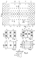
- FIG. 3 shows a guide surface 1 which has nozzles 2 which are supplied with air by means of air supply boxes 16 and 16 '.
- the top view of the guide surface 1 is shown, the partitions being shown as lines and ensuring the division into different air supply boxes 16 and 16 '.
- the surface density of the nozzles 2 designed as slot nozzles 18 is preferably designed differently.
- two air supply boxes 16 are arranged in the inlet area 11, which have a high surface density of nozzles 2.
- This is followed by a guide zone 14 with a surface density of nozzles 2, which is stronger in the central region and weaker at the edges.
- This guide zone 14 corresponds, for example, to the nozzle areas 40, 42 in which blowing air is sufficient for every operation of the printing press.
- the guide zone 14 is followed by the outlet area 12, viewed in the direction of sheet travel 24, which has a higher nozzle density has, and in the relatively large holding forces must act on the sheet 4 in suction air operation.
- FIG. 4 shows how axial fans 15 can be assigned to the air supply boxes 16 and 16 ′ shown in FIG. 3.
- This arrangement essentially corresponds to the arrangement of air supply boxes with partitions 44, 46, 48 shown in FIG. 2.
- FIG. 6 shows how a subdivision can be dispensed with if the air requirement is less, so that in each case a blow box 16 is arranged in the inlet area 11 and in the outlet area 12 and a large blow box 16 '' 'is arranged in the guide zone 14.
- the nozzle arrangement which is shown in FIG. 7, is designed accordingly.
- FIG. 8 shows the preferred embodiment of the nozzles 2, which has already been indicated in FIG. 3.
- These are slot nozzles 18, which can be stamped into the sheet metal of the guide surfaces 1 in a simple manner.
- the blowing direction is directed outwards (arrows 50), as a result of which the sheet 4 is tightened transversely to its running direction.
- two strong outward air streams are formed in the middle, which move to the side of the sheet 4, and which can be maintained outwards by means of a smaller number of nozzles 2, 18.
- nozzle areas 52, 54 are provided in the inlet area 11 and / or in the outlet area 12 of the guide surface 1, the nozzles of which can be switched between blowing and suction operation depending on the printing material to be processed.
- the remaining nozzles of the guide surface 1 are preferably operated in blowing mode in this embodiment of the invention.
- the nozzle areas 52, 54 preferably each have a fan 15 assigned to them, are preferably arranged in the center of the sheet track 17 and have a width which is less than the smallest sheet format which can be processed by the printing press.
- the exemplary embodiments merely represent possibilities for the configuration of the sheet guiding device according to the invention, further embodiments with different nozzle arrangements, possibly also other blowing directions, are possible.
- a central air supply with blowing and suction air or another type of fan can also be used.
Landscapes
- Engineering & Computer Science (AREA)
- Mechanical Engineering (AREA)
- Feeding Of Articles By Means Other Than Belts Or Rollers (AREA)
- Supply, Installation And Extraction Of Printed Sheets Or Plates (AREA)
- Delivering By Means Of Belts And Rollers (AREA)
Applications Claiming Priority (2)
| Application Number | Priority Date | Filing Date | Title |
|---|---|---|---|
| DE19503110A DE19503110B4 (de) | 1995-02-01 | 1995-02-01 | Bogenleiteinrichtung für Druckmaschinen |
| DE19503110 | 1995-02-01 |
Publications (3)
| Publication Number | Publication Date |
|---|---|
| EP0725025A2 true EP0725025A2 (fr) | 1996-08-07 |
| EP0725025A3 EP0725025A3 (fr) | 1997-07-09 |
| EP0725025B1 EP0725025B1 (fr) | 1998-04-08 |
Family
ID=7752817
Family Applications (1)
| Application Number | Title | Priority Date | Filing Date |
|---|---|---|---|
| EP95119931A Expired - Lifetime EP0725025B1 (fr) | 1995-02-01 | 1995-12-18 | Dispositif de guidage de feuilles pour machines à imprimer |
Country Status (4)
| Country | Link |
|---|---|
| US (1) | US5816155A (fr) |
| EP (1) | EP0725025B1 (fr) |
| JP (3) | JPH08244206A (fr) |
| DE (3) | DE19503110B4 (fr) |
Cited By (7)
| Publication number | Priority date | Publication date | Assignee | Title |
|---|---|---|---|---|
| EP0941844A1 (fr) * | 1998-03-11 | 1999-09-15 | Autz + Herrmann Metallwaren- und Maschinenfabrik | Dispositif de guidage de feuilles |
| EP1010525A1 (fr) * | 1998-12-15 | 2000-06-21 | MAN Roland Druckmaschinen AG | Dispositif de guidage de feuilles pour une machine d'impression |
| EP1123805A1 (fr) * | 2000-02-10 | 2001-08-16 | Mitsubishi Heavy Industries, Ltd. | Unité de conduite des feuilles pour une machine à imprimer à feuilles |
| EP1123803A1 (fr) * | 2000-02-08 | 2001-08-16 | Mitsubishi Heavy Industries, Ltd. | Unité de conduite des feuilles pour une machine à imprimer à feuilles |
| EP1044909A3 (fr) * | 1999-04-06 | 2002-12-18 | Heidelberger Druckmaschinen Aktiengesellschaft | Dispositif et procédé pour le guidage d'un bord ouvert d'un cahier pendent le transfert |
| EP1184174A3 (fr) * | 2000-08-31 | 2004-03-17 | Heidelberger Druckmaschinen Aktiengesellschaft | Machine de traitement de feuilles |
| EP2889242A4 (fr) * | 2012-08-22 | 2016-05-18 | Fujifilm Corp | Dispositif de transport de support d'enregistrement, et dispositif d'enregistrement à jet d'encre |
Families Citing this family (45)
| Publication number | Priority date | Publication date | Assignee | Title |
|---|---|---|---|---|
| DE19503110B4 (de) | 1995-02-01 | 2009-01-29 | Heidelberger Druckmaschinen Ag | Bogenleiteinrichtung für Druckmaschinen |
| DE19701230C1 (de) * | 1997-01-16 | 1998-02-19 | Roland Man Druckmasch | Pneumatische Bogenleiteinrichtung in einer Druckmaschine |
| EP0858888B2 (fr) * | 1997-02-13 | 2007-03-07 | Maschinenfabrik Gietz Ag | Presse d'estampage à plat |
| DE19859246A1 (de) * | 1998-01-20 | 1999-07-22 | Koch Hans Peter | Bogenoffsetdruckverfahren und Bogenoffsetdruckmaschine |
| US5913268A (en) * | 1998-02-17 | 1999-06-22 | Xerox Corporation | Pneumatic rollers and paper handling arrangements |
| DE19914178B4 (de) * | 1998-04-27 | 2006-07-06 | Heidelberger Druckmaschinen Ag | Bogenleiteinrichtung in einer Bogendruckmaschine |
| DE19921271A1 (de) * | 1998-06-03 | 1999-12-09 | Heidelberger Druckmasch Ag | Verfahren zum Fördern von Bogen in einer Druckmaschine sowie eine Vorrichtung zur Durchführung des Verfahrens |
| DE19829094C2 (de) * | 1998-06-30 | 2002-10-24 | Roland Man Druckmasch | Leiteinrichtung für bogenförmige Bedruckstoffe in einer Druckmaschine |
| DE19905095C2 (de) * | 1999-02-09 | 2001-02-22 | Roland Man Druckmasch | Bogenführungseinrichtung für eine Druckmaschine |
| DE10007249A1 (de) | 1999-03-29 | 2000-10-05 | Heidelberger Druckmasch Ag | Ausleger für eine Bogen verarbeitende Druckmaschine |
| DE10049809B4 (de) * | 1999-10-28 | 2014-02-13 | Heidelberger Druckmaschinen Ag | Leitvorrichtung für einen flächenhaften Bedruckstoff |
| US6585263B1 (en) | 2000-02-02 | 2003-07-01 | Heidelberger Druckmaschinen Ag | Deceleration drum assembly containing air guides |
| DE10005391A1 (de) * | 2000-02-07 | 2001-08-09 | Roland Man Druckmasch | Verfahren und Vorrichtung zur Bogenführung in einer Rotationsdruckmaschine |
| DE60010216T2 (de) * | 2000-02-10 | 2005-01-27 | Mitsubishi Heavy Industries, Ltd. | Bogenführungseinheit in einer Bogendruckmaschine |
| DE10011979C5 (de) * | 2000-03-11 | 2008-02-14 | Man Roland Druckmaschinen Ag | Einrichtung zur Bogenführung in einer Druckmaschine |
| DE10141415A1 (de) | 2000-08-31 | 2002-03-14 | Heidelberger Druckmasch Ag | Vorrichtung zum Führen von Bogen in einer Bogen verarbeitenden Maschine |
| DE10150842B4 (de) * | 2000-11-15 | 2013-11-21 | Heidelberger Druckmaschinen Ag | Speichereinrichtung zur Wendung bogenförmigen Materials |
| DE10060557B4 (de) * | 2000-12-06 | 2007-05-31 | Man Roland Druckmaschinen Ag | Bogenleiteinrichtung in einer Rotationsdruckmaschine |
| US6934508B2 (en) * | 2001-03-19 | 2005-08-23 | Navigaug Inc. | System and method for obtaining comprehensive vehicle radio listener statistics |
| CN100434271C (zh) * | 2001-07-23 | 2008-11-19 | 三菱重工业株式会社 | 单张纸传送印刷机 |
| DE10152593A1 (de) * | 2001-10-24 | 2003-05-08 | Koenig & Bauer Ag | Einrichtung zur Bedruckstoff- und Druckwerkskühlung mittels gekühlter Blasluft an Bogenrotationsdruckmaschinen |
| EP1352738A3 (fr) * | 2002-04-08 | 2004-08-04 | Komori Corporation | Appareil de guidage de feuilles |
| DE102004002660B4 (de) | 2003-01-31 | 2013-06-13 | Heidelberger Druckmaschinen Ag | Verfahren zum Betreiben einer Bogendruckmaschine und Bogendruckmaschine zur Durchführung dieses Verfahrens |
| US20050070415A1 (en) * | 2003-09-30 | 2005-03-31 | Haasl Andrew L. | Assembly for and method of preventing buildup of debris in a folding roll tucker assembly |
| WO2005047000A1 (fr) * | 2003-11-17 | 2005-05-26 | Silverbrook Research Pty Ltd | Ensemble boitier de ventilateur pour imprimante |
| JP4092302B2 (ja) * | 2004-04-01 | 2008-05-28 | ソニーケミカル&インフォメーションデバイス株式会社 | サクション装置 |
| DE102004021730B4 (de) * | 2004-04-30 | 2011-08-18 | KOENIG & BAUER Aktiengesellschaft, 97080 | Bogenführungseinrichtung in Druckmaschinen |
| DE102004058377A1 (de) * | 2004-12-03 | 2006-06-14 | Man Roland Druckmaschinen Ag | Bogenleiteinrichtung für eine bogenverarbeitende Maschine, insbesondere Rotationsbogendruckmaschine |
| JP4369357B2 (ja) * | 2004-12-21 | 2009-11-18 | 株式会社小森コーポレーション | シート状物案内装置 |
| DE102005014257A1 (de) * | 2005-03-30 | 2006-10-05 | Koenig & Bauer Ag | Leiteinrichtung zum Fördern von flächigen Bedruckstoffen auf einem Luftpolster |
| JP2006347702A (ja) * | 2005-06-16 | 2006-12-28 | Komori Corp | シート状物案内装置 |
| US7735829B2 (en) * | 2006-11-06 | 2010-06-15 | Heidelberger Druckmaschinen Ag | Method and apparatus for turning a sheet during its transport through a printing press |
| JP5068203B2 (ja) | 2008-03-17 | 2012-11-07 | 富士フイルム株式会社 | インクジェット記録装置、インクジェット記録方法 |
| JP2009220954A (ja) * | 2008-03-17 | 2009-10-01 | Fujifilm Corp | インクジェット記録装置、インクジェット記録方法 |
| JP5202054B2 (ja) * | 2008-03-17 | 2013-06-05 | リョービ株式会社 | 印刷機における枚葉紙受渡し装置 |
| JP4963683B2 (ja) * | 2008-03-31 | 2012-06-27 | 富士フイルム株式会社 | インクジェット記録装置 |
| JP5322265B2 (ja) | 2008-05-23 | 2013-10-23 | 富士フイルム株式会社 | 画像形成方法 |
| JP5106246B2 (ja) | 2008-05-23 | 2012-12-26 | 富士フイルム株式会社 | インクジェット記録方法及び装置 |
| CN102700243B (zh) * | 2011-03-28 | 2016-04-06 | 海德堡印刷机械股份公司 | 用于输送页张的装置 |
| JP5363539B2 (ja) * | 2011-07-29 | 2013-12-11 | 富士フイルム株式会社 | インクジェット記録装置 |
| WO2014083722A1 (fr) * | 2012-11-28 | 2014-06-05 | 大和グランド株式会社 | Procédé d'impression utilisant une imprimante offset |
| DE102014216286A1 (de) * | 2014-08-15 | 2016-02-18 | Koenig & Bauer Ag | Vorrichtung zum Führen von Bogen in einer Bogenrotationsdruckmaschine |
| US9378714B1 (en) | 2015-02-10 | 2016-06-28 | Kevin L. Baldwin, Sr. | Electronic drum |
| TWI812812B (zh) * | 2018-12-20 | 2023-08-21 | 美商凱特伊夫公司 | 使用具有溫度控制的基材支撐件之噴墨式印刷機以及將材料沉積在基材上的方法 |
| JP7686985B2 (ja) * | 2021-01-22 | 2025-06-03 | 株式会社リコー | シート積載装置、印刷装置 |
Citations (1)
| Publication number | Priority date | Publication date | Assignee | Title |
|---|---|---|---|---|
| DE3411029C2 (fr) | 1984-03-24 | 1987-10-08 | M.A.N.- Roland Druckmaschinen Ag, 6050 Offenbach, De |
Family Cites Families (23)
| Publication number | Priority date | Publication date | Assignee | Title |
|---|---|---|---|---|
| DE555814C (de) * | 1928-11-11 | 1932-07-29 | Hamburger Fremdenblatt Brosche | Mehrfarben-Rotationsdruckmaschine fuer Bogen |
| DE1499078B2 (de) * | 1966-11-23 | 1973-03-29 | Vits-Maschinenbau Gmbh, 4018 Langenfeld | Verfahren und einrichtung zur stabilisierung der lage einer warenbahn bei schwebender durchfuehrung dieser durch einen mindestens teilweise tragfluegelprofilbegrenzten behandlungsraum mittels eines blasmittels, mit dem wenigstens eine warenbahnflaeche im spitzen winkel zu ihrer bewegungsrichtung angeblasen wird |
| DE1907083C3 (de) * | 1969-02-13 | 1975-12-18 | Vits-Maschinenbau Gmbh, 4018 Langenfeld | Blaskasten zum schwebenden Führen und/oder Fördern von Bahnen oder Bogen |
| US3684081A (en) * | 1970-09-14 | 1972-08-15 | Masaharu Matsuo | Sheet transfer device |
| US4029009A (en) * | 1975-07-17 | 1977-06-14 | Veb Polygraph Leipzig Kombinat Fur Polygraphische Maschinen Und Ausrustungen | Printing machine construction |
| DD125394A1 (fr) * | 1976-02-27 | 1977-04-20 | ||
| US4099463A (en) * | 1977-04-13 | 1978-07-11 | Veb Polygraph Leipzig Kombinat Fuer Polygraphische Maschinen Und Ausruestungen | Support arrangement for guiding sheets through a printing machine |
| DE2802610C2 (de) * | 1978-01-21 | 1983-05-05 | Vits-Maschinenbau Gmbh, 4018 Langenfeld | Blaskasten zum schwebenden Führen und/oder Fördern von Bahnen oder Bogen |
| DE2911685C2 (de) * | 1979-03-24 | 1981-03-12 | Vits-Maschinenbau Gmbh, 4018 Langenfeld | Blaskasten zum schwebenden Führen von Warenbahnen |
| DE3443704A1 (de) * | 1984-11-30 | 1986-06-05 | Roland Man Druckmasch | Vorrichtung zum fuehren von ein- oder beidseitig bedruckten bogen |
| DD241042A1 (de) * | 1985-09-23 | 1986-11-26 | Polygraph Leipzig | Bogenleiteinrichtung in druckmaschinen |
| DE8915626U1 (de) * | 1989-11-06 | 1991-02-21 | Vits, Hilmar, 5653 Leichlingen | Vorrichtung zum schwebenden Führen von zu fördernden Materialbahnen oder Materialbogen |
| US5243909A (en) * | 1990-12-31 | 1993-09-14 | Howard W. DeMoore | Vacuum transfer apparatus for rotary sheet-fed printing presses |
| DE4209067C2 (de) * | 1992-03-20 | 1997-03-13 | Kba Planeta Ag | Bogenleiteinrichtung |
| DE4242731A1 (de) * | 1992-12-17 | 1994-06-23 | Heidelberger Druckmasch Ag | Vorrichtung zum seitlichen Ausrichten von Bogen in Druckmaschinen |
| DE4308276C2 (de) * | 1993-03-16 | 1997-09-04 | Heidelberger Druckmasch Ag | Leiteinrichtung für einen Bogen |
| DE4406844C2 (de) * | 1994-03-03 | 1997-05-07 | Koenig & Bauer Albert Ag | Vorrichtung zum Führen von frisch beschichteten Bogen |
| DE4410189A1 (de) * | 1994-03-24 | 1995-09-28 | Heidelberger Druckmasch Ag | Leiteinrichtung für bewegtes Bogenmatrial in Druckmaschinen |
| DE4447963B4 (de) * | 1994-08-03 | 2005-12-29 | Heidelberger Druckmaschinen Ag | Einrichtung zum berührungsfreien Führen bogenförmigen Materials |
| US5509352A (en) * | 1994-09-23 | 1996-04-23 | Ward Holding Company | Paperboard processing machine with vacuum transfer system |
| DE29501537U1 (de) * | 1995-02-01 | 1995-03-09 | Heidelberger Druckmaschinen Ag, 69115 Heidelberg | Bogenleiteinrichtung mit Luftversorgungskästen |
| DE19503110B4 (de) | 1995-02-01 | 2009-01-29 | Heidelberger Druckmaschinen Ag | Bogenleiteinrichtung für Druckmaschinen |
| US5488905A (en) * | 1995-04-10 | 1996-02-06 | Howard W. DeMoore | Air-dam for printing press vacuum transfer apparatus |
-
1995
- 1995-02-01 DE DE19503110A patent/DE19503110B4/de not_active Expired - Fee Related
- 1995-02-01 DE DE19549589A patent/DE19549589B4/de not_active Expired - Lifetime
- 1995-12-18 DE DE59501845T patent/DE59501845D1/de not_active Expired - Lifetime
- 1995-12-18 EP EP95119931A patent/EP0725025B1/fr not_active Expired - Lifetime
-
1996
- 1996-01-30 JP JP8014023A patent/JPH08244206A/ja active Pending
-
1997
- 1997-05-15 US US08/857,133 patent/US5816155A/en not_active Expired - Lifetime
-
1998
- 1998-06-30 JP JP10184383A patent/JP3025477B2/ja not_active Expired - Fee Related
-
2000
- 2000-02-01 JP JP2000024057A patent/JP3444487B2/ja not_active Expired - Lifetime
Patent Citations (1)
| Publication number | Priority date | Publication date | Assignee | Title |
|---|---|---|---|---|
| DE3411029C2 (fr) | 1984-03-24 | 1987-10-08 | M.A.N.- Roland Druckmaschinen Ag, 6050 Offenbach, De |
Cited By (10)
| Publication number | Priority date | Publication date | Assignee | Title |
|---|---|---|---|---|
| EP0941844A1 (fr) * | 1998-03-11 | 1999-09-15 | Autz + Herrmann Metallwaren- und Maschinenfabrik | Dispositif de guidage de feuilles |
| WO1999046123A3 (fr) * | 1998-03-11 | 1999-12-09 | Heidelberger Druckmasch Ag | Dispositif d'alimentation en feuilles |
| US6416051B1 (en) | 1998-03-11 | 2002-07-09 | Heidelberger Druckmaschinen | Sheet guiding device and method of production |
| EP1010525A1 (fr) * | 1998-12-15 | 2000-06-21 | MAN Roland Druckmaschinen AG | Dispositif de guidage de feuilles pour une machine d'impression |
| EP1044909A3 (fr) * | 1999-04-06 | 2002-12-18 | Heidelberger Druckmaschinen Aktiengesellschaft | Dispositif et procédé pour le guidage d'un bord ouvert d'un cahier pendent le transfert |
| EP1123803A1 (fr) * | 2000-02-08 | 2001-08-16 | Mitsubishi Heavy Industries, Ltd. | Unité de conduite des feuilles pour une machine à imprimer à feuilles |
| EP1123805A1 (fr) * | 2000-02-10 | 2001-08-16 | Mitsubishi Heavy Industries, Ltd. | Unité de conduite des feuilles pour une machine à imprimer à feuilles |
| EP1184174A3 (fr) * | 2000-08-31 | 2004-03-17 | Heidelberger Druckmaschinen Aktiengesellschaft | Machine de traitement de feuilles |
| EP2889242A4 (fr) * | 2012-08-22 | 2016-05-18 | Fujifilm Corp | Dispositif de transport de support d'enregistrement, et dispositif d'enregistrement à jet d'encre |
| US9427986B2 (en) | 2012-08-22 | 2016-08-30 | Fujifilm Corporation | Print medium-conveying device and inkjet printing device |
Also Published As
| Publication number | Publication date |
|---|---|
| EP0725025A3 (fr) | 1997-07-09 |
| JP2000168047A (ja) | 2000-06-20 |
| EP0725025B1 (fr) | 1998-04-08 |
| US5816155A (en) | 1998-10-06 |
| DE19503110B4 (de) | 2009-01-29 |
| JPH08244206A (ja) | 1996-09-24 |
| JPH11245380A (ja) | 1999-09-14 |
| JP3444487B2 (ja) | 2003-09-08 |
| JP3025477B2 (ja) | 2000-03-27 |
| DE19503110A1 (de) | 1996-08-08 |
| DE19549589B4 (de) | 2005-11-17 |
| DE59501845D1 (de) | 1998-05-14 |
Similar Documents
| Publication | Publication Date | Title |
|---|---|---|
| EP0725025B1 (fr) | Dispositif de guidage de feuilles pour machines à imprimer | |
| EP0695707B1 (fr) | Dispositif pour le guidage sans contact d'un matériau en forme de feuille | |
| DE29501537U1 (de) | Bogenleiteinrichtung mit Luftversorgungskästen | |
| DE102009039278A1 (de) | Formatvariable Rollendruckmaschine | |
| EP2293940B2 (fr) | Presse offset rotative | |
| DE4239561C2 (de) | Kettenförderer einer Bogendruckmaschine | |
| EP0899228B1 (fr) | Dispositif de guidage à coussin d'air | |
| DE10102221A1 (de) | Vorrichtung zum Verlangsamen von Signaturen | |
| DE102019118565A1 (de) | Bogenverarbeitende Maschine und Verfahren zum Fördern von Bogen | |
| EP0788878A1 (fr) | Procédé et dispositif pour guider une bande entre deux cylindres d'une machine à imprimer | |
| DE19814006C1 (de) | Verfahren und Einrichtung zur Bogenführung an einer Leitrakel in Druckmaschinen | |
| DE10112759A1 (de) | Verfahren und Vorrichtung zur berührungslosen Führung von Bogen | |
| DE29817317U1 (de) | Bogenführungseinrichtung mit einer Führungsfläche in einer Druckmaschine | |
| DD285072A5 (de) | Blaseinrichtung | |
| DE102015215166A1 (de) | Vorrichtung zum Behandeln von Bogen | |
| DE3427570A1 (de) | Vorrichtung zum falzen und weiterverarbeiten von druckexemplaren | |
| DE4342203C2 (de) | Einrichtung zum Einwirken auf Bogen in einer Bogenrotationsdruckmaschine | |
| DE102017217843B4 (de) | Vorrichtung zum Behandeln von Bogen | |
| DE102016211627B4 (de) | Verfahren zum Betreiben einer Blaseinrichtung | |
| DE102019118569A1 (de) | Bogenverarbeitende Maschine und Verfahren zum Fördern von Bogen | |
| DE102019009156A1 (de) | Bogenverarbeitende Maschine und Verfahren zum Fördern von Bogen | |
| DE10059587A1 (de) | Verfahren und Vorrichtung zum Falzen von Materialbogen | |
| DE102019118566A1 (de) | Bogenverarbeitende Maschine und Verfahren zum Fördern von Bogen | |
| DE102013209699B4 (de) | Bogenführungseinrichtung für eine bogenverarbeitende Maschine | |
| EP1741651A2 (fr) | Frein de feuilles dans le dispositif de sortie d'une machine à imprimer |
Legal Events
| Date | Code | Title | Description |
|---|---|---|---|
| PUAI | Public reference made under article 153(3) epc to a published international application that has entered the european phase |
Free format text: ORIGINAL CODE: 0009012 |
|
| 17P | Request for examination filed |
Effective date: 19951218 |
|
| AK | Designated contracting states |
Kind code of ref document: A2 Designated state(s): DE FR GB |
|
| PUAL | Search report despatched |
Free format text: ORIGINAL CODE: 0009013 |
|
| AK | Designated contracting states |
Kind code of ref document: A3 Designated state(s): DE FR GB |
|
| GRAG | Despatch of communication of intention to grant |
Free format text: ORIGINAL CODE: EPIDOS AGRA |
|
| GRAG | Despatch of communication of intention to grant |
Free format text: ORIGINAL CODE: EPIDOS AGRA |
|
| GRAH | Despatch of communication of intention to grant a patent |
Free format text: ORIGINAL CODE: EPIDOS IGRA |
|
| 17Q | First examination report despatched |
Effective date: 19970829 |
|
| GRAH | Despatch of communication of intention to grant a patent |
Free format text: ORIGINAL CODE: EPIDOS IGRA |
|
| GRAA | (expected) grant |
Free format text: ORIGINAL CODE: 0009210 |
|
| AK | Designated contracting states |
Kind code of ref document: B1 Designated state(s): DE FR GB |
|
| REF | Corresponds to: |
Ref document number: 59501845 Country of ref document: DE Date of ref document: 19980514 |
|
| ET | Fr: translation filed | ||
| GBT | Gb: translation of ep patent filed (gb section 77(6)(a)/1977) |
Effective date: 19980630 |
|
| PLBE | No opposition filed within time limit |
Free format text: ORIGINAL CODE: 0009261 |
|
| STAA | Information on the status of an ep patent application or granted ep patent |
Free format text: STATUS: NO OPPOSITION FILED WITHIN TIME LIMIT |
|
| 26N | No opposition filed | ||
| REG | Reference to a national code |
Ref country code: GB Ref legal event code: IF02 |
|
| PGFP | Annual fee paid to national office [announced via postgrant information from national office to epo] |
Ref country code: GB Payment date: 20021125 Year of fee payment: 8 |
|
| PGFP | Annual fee paid to national office [announced via postgrant information from national office to epo] |
Ref country code: FR Payment date: 20021217 Year of fee payment: 8 |
|
| PG25 | Lapsed in a contracting state [announced via postgrant information from national office to epo] |
Ref country code: GB Free format text: LAPSE BECAUSE OF NON-PAYMENT OF DUE FEES Effective date: 20031218 |
|
| GBPC | Gb: european patent ceased through non-payment of renewal fee |
Effective date: 20031218 |
|
| PG25 | Lapsed in a contracting state [announced via postgrant information from national office to epo] |
Ref country code: FR Free format text: LAPSE BECAUSE OF NON-PAYMENT OF DUE FEES Effective date: 20040831 |
|
| REG | Reference to a national code |
Ref country code: FR Ref legal event code: ST |
|
| PGFP | Annual fee paid to national office [announced via postgrant information from national office to epo] |
Ref country code: DE Payment date: 20130128 Year of fee payment: 18 |
|
| REG | Reference to a national code |
Ref country code: DE Ref legal event code: R119 Ref document number: 59501845 Country of ref document: DE |
|
| REG | Reference to a national code |
Ref country code: DE Ref legal event code: R119 Ref document number: 59501845 Country of ref document: DE Effective date: 20140701 |
|
| PG25 | Lapsed in a contracting state [announced via postgrant information from national office to epo] |
Ref country code: DE Free format text: LAPSE BECAUSE OF NON-PAYMENT OF DUE FEES Effective date: 20140701 |