EP0725194A1 - Dispositif de drainage pour balcons - Google Patents
Dispositif de drainage pour balcons Download PDFInfo
- Publication number
- EP0725194A1 EP0725194A1 EP96101255A EP96101255A EP0725194A1 EP 0725194 A1 EP0725194 A1 EP 0725194A1 EP 96101255 A EP96101255 A EP 96101255A EP 96101255 A EP96101255 A EP 96101255A EP 0725194 A1 EP0725194 A1 EP 0725194A1
- Authority
- EP
- European Patent Office
- Prior art keywords
- profile
- section
- dirty water
- drainage system
- channel
- Prior art date
- Legal status (The legal status is an assumption and is not a legal conclusion. Google has not performed a legal analysis and makes no representation as to the accuracy of the status listed.)
- Granted
Links
- 238000004873 anchoring Methods 0.000 claims abstract description 39
- XLYOFNOQVPJJNP-UHFFFAOYSA-N water Substances O XLYOFNOQVPJJNP-UHFFFAOYSA-N 0.000 claims description 123
- 239000002351 wastewater Substances 0.000 claims description 53
- 230000000149 penetrating effect Effects 0.000 claims description 10
- 230000000295 complement effect Effects 0.000 claims description 6
- 238000011161 development Methods 0.000 description 9
- 230000018109 developmental process Effects 0.000 description 9
- 230000008901 benefit Effects 0.000 description 6
- 230000004048 modification Effects 0.000 description 6
- 238000012986 modification Methods 0.000 description 6
- 238000009434 installation Methods 0.000 description 5
- 238000007789 sealing Methods 0.000 description 5
- 238000011109 contamination Methods 0.000 description 4
- 238000004519 manufacturing process Methods 0.000 description 4
- 229910052751 metal Inorganic materials 0.000 description 4
- 239000002184 metal Substances 0.000 description 4
- 238000000034 method Methods 0.000 description 4
- 230000008569 process Effects 0.000 description 4
- 239000000853 adhesive Substances 0.000 description 3
- 230000001070 adhesive effect Effects 0.000 description 3
- 238000001125 extrusion Methods 0.000 description 3
- 239000004033 plastic Substances 0.000 description 3
- 229920003023 plastic Polymers 0.000 description 3
- 230000000694 effects Effects 0.000 description 2
- 239000007788 liquid Substances 0.000 description 2
- 230000007704 transition Effects 0.000 description 2
- 229910000838 Al alloy Inorganic materials 0.000 description 1
- 230000015572 biosynthetic process Effects 0.000 description 1
- 230000008859 change Effects 0.000 description 1
- 239000011248 coating agent Substances 0.000 description 1
- 238000000576 coating method Methods 0.000 description 1
- 230000006735 deficit Effects 0.000 description 1
- 230000002349 favourable effect Effects 0.000 description 1
- 230000009969 flowable effect Effects 0.000 description 1
- 239000000463 material Substances 0.000 description 1
- 239000007769 metal material Substances 0.000 description 1
- 239000010814 metallic waste Substances 0.000 description 1
- 230000008092 positive effect Effects 0.000 description 1
- 238000003825 pressing Methods 0.000 description 1
- 230000003014 reinforcing effect Effects 0.000 description 1
- 238000009418 renovation Methods 0.000 description 1
- 238000009420 retrofitting Methods 0.000 description 1
- 239000010865 sewage Substances 0.000 description 1
- 239000010935 stainless steel Substances 0.000 description 1
- 230000000007 visual effect Effects 0.000 description 1
- 238000003466 welding Methods 0.000 description 1
Images


Classifications
-
- E—FIXED CONSTRUCTIONS
- E04—BUILDING
- E04D—ROOF COVERINGS; SKY-LIGHTS; GUTTERS; ROOF-WORKING TOOLS
- E04D13/00—Special arrangements or devices in connection with roof coverings; Protection against birds; Roof drainage ; Sky-lights
- E04D13/04—Roof drainage; Drainage fittings in flat roofs, balconies or the like
- E04D13/064—Gutters
- E04D13/072—Hanging means
- E04D13/0727—Hanging means situated mainly at the rear side of the gutter
-
- E—FIXED CONSTRUCTIONS
- E04—BUILDING
- E04D—ROOF COVERINGS; SKY-LIGHTS; GUTTERS; ROOF-WORKING TOOLS
- E04D13/00—Special arrangements or devices in connection with roof coverings; Protection against birds; Roof drainage ; Sky-lights
- E04D13/04—Roof drainage; Drainage fittings in flat roofs, balconies or the like
- E04D13/0404—Drainage on the roof surface
- E04D13/0459—Drainage borders, e.g. dripping edges, gravel stops or dispersers
-
- E—FIXED CONSTRUCTIONS
- E04—BUILDING
- E04D—ROOF COVERINGS; SKY-LIGHTS; GUTTERS; ROOF-WORKING TOOLS
- E04D13/00—Special arrangements or devices in connection with roof coverings; Protection against birds; Roof drainage ; Sky-lights
- E04D13/04—Roof drainage; Drainage fittings in flat roofs, balconies or the like
- E04D13/064—Gutters
-
- E—FIXED CONSTRUCTIONS
- E04—BUILDING
- E04D—ROOF COVERINGS; SKY-LIGHTS; GUTTERS; ROOF-WORKING TOOLS
- E04D13/00—Special arrangements or devices in connection with roof coverings; Protection against birds; Roof drainage ; Sky-lights
- E04D13/15—Trimming strips; Edge strips; Fascias; Expansion joints for roofs
- E04D13/155—Trimming strips; Edge strips; Fascias; Expansion joints for roofs retaining the roof sheathing
-
- E—FIXED CONSTRUCTIONS
- E04—BUILDING
- E04D—ROOF COVERINGS; SKY-LIGHTS; GUTTERS; ROOF-WORKING TOOLS
- E04D13/00—Special arrangements or devices in connection with roof coverings; Protection against birds; Roof drainage ; Sky-lights
- E04D13/04—Roof drainage; Drainage fittings in flat roofs, balconies or the like
- E04D13/0404—Drainage on the roof surface
- E04D13/0459—Drainage borders, e.g. dripping edges, gravel stops or dispersers
- E04D2013/0463—Dispersers
-
- E—FIXED CONSTRUCTIONS
- E04—BUILDING
- E04D—ROOF COVERINGS; SKY-LIGHTS; GUTTERS; ROOF-WORKING TOOLS
- E04D13/00—Special arrangements or devices in connection with roof coverings; Protection against birds; Roof drainage ; Sky-lights
- E04D13/04—Roof drainage; Drainage fittings in flat roofs, balconies or the like
- E04D13/0404—Drainage on the roof surface
- E04D13/0459—Drainage borders, e.g. dripping edges, gravel stops or dispersers
- E04D2013/0468—Drip edges
Definitions
- the invention relates to a drainage system for balconies, which consist of a support plate and screed applied thereon.
- the drainage system comprises at least one elongated end profile, which has an essentially flat anchoring leg that can be placed on the supporting plate of the balcony before the screed is applied, on the outside of the balcony of which there is a profile section that protects the supporting plate and the screed from external weather influences.
- This profile section is composed of a profile leg which has approximately the height of the screed and essentially protrudes upward at right angles and a profile leg which points obliquely downwards and at least partially covers the support plate.
- Such an end profile is known from German utility model 90 04 119. This end profile is used to keep driving rain or liquid flowing off the front edge of the balcony away from the front wall of the balcony, so that no moisture can penetrate into the screed or the support plate from there.
- the invention has for its object to provide a drainage system for balconies, which allows a drainage of dirty water such that an underlying balcony - or even a ground floor terrace - is not affected by dirty water discharged from the balcony above, without doing so on conventional gutters to have to fall back.
- This object is achieved in that in a drainage system of the type mentioned in the a wastewater drainage channel is provided at an angle downwards.
- the cross section of the dirty water drainage channel can be essentially U-shaped or also arch-like.
- the dirty water drainage channel projects beyond at least one of the two ends of the elongated end profile. This ensures that in the dirty water channel of a balcony, waste water running to this end is drained away without further measures in a direction away from the balconies or a terrace below this balcony.
- the dirty water drainage channel can have an opening facing away from the balcony, on which a dirty water spout is provided.
- wastewater spout is understood to mean a short water baffle or pipe.
- the opening can be provided at any point in the longitudinal direction of the profile, so that it is possible to discharge the dirty water from the dirty water drainage channel at a desired, advantageous point.
- the waste water drainage channel is an integral part of the end profile. This allows a cost-effective production of the end profile and waste water drainage channel in a single operation, e.g. in the extrusion process.
- the dirty water drainage channel is a separately manufactured component that can be attached to the end profile.
- Such a design of the end profile allows attachment of the Dirty water drainage channel even after completion of the balcony.
- a particularly advantageous way of attaching the waste water drainage channel to the end profile is possible if the obliquely downward profile leg of the end profile has an elongated groove-like depression with a narrowed mouth, into which the dirty water drainage channel can then be inserted or hooked.
- Such a configuration of the end profile and the waste water drainage channel makes it easy to install the waste water drainage channel without additional tools or fastening means such as e.g. Screws or rivets possible.
- End profiles are known in which a profile strip which is bent downward into a position approximately parallel to the side wall of the balcony is connected at the edge of the profile leg facing away from the anchoring leg.
- an elongated groove-like depression with a narrowed mouth which extends in the longitudinal direction of the profile and into which the dirty water drainage channel can be inserted or hooked in, is then provided on this profile strip.
- the end face of the profile strip facing away from the sloping downward profile leg can beveled towards the balcony, so that a drip edge for the dirty water forms on the side of the end face facing away from the balcony.
- the said narrowed mouths can be formed by two rib-like strip sections formed on the end profile at a parallel distance from the associated flat side.
- This has the advantage that the recess simple and inexpensive - in the case of a metallic end profile, for example in the extrusion process - can be produced, so that such a depression does not have to be subsequently milled into the profile, for example.
- the advantageous type of manufacture will be discussed in the description of the figures.
- a stiffening effect is achieved with these rib-like strip sections, which stiffens the end profile both during installation and during transport and makes it less susceptible to twisting. This means that such end profiles are bent less frequently during transport and are therefore rendered unusable.
- the stiffening and reinforcing effect not only has a positive effect during transport, it is also much easier to install on site with a stiffer profile than with a flexible one.
- the dirty water drainage channel can advantageously be designed such that a fastening section running in the longitudinal direction of the channel is provided, which can be inserted or hooked into the groove-like recess of the end profile and which has a cross section which is at least partially complementary to the cross section of the groove-like recess.
- the fastening section can have a strip section covering the side of the narrowed mouth facing away from the groove-like recess, a strip section penetrating the mouth and a strip section attached to the recess-side end of the strip section penetrating the mouth, approximately parallel to the strip section which forms an inner surface of the recess and forms the end profile.
- the height of the strip section folded over parallel to the inner surface of the depression opposite the mouth is maximally the same to measure the width of the mouth of the groove-like recess, so that the dirty water drainage channel can be hung anywhere in the end profile.
- the attachment can be facilitated in that the flank of the strip section pointing from the drainage channel to the flat section of the end profile which is parallel to the flat surface of the recess forming an inner surface of the recess is beveled at least over part of its height towards the strip section passing through the mouth.
- a dirty water spout can be arranged at at least one end of the channel. This spout drains the dirty water in any direction.
- a separately produced end cap can be slid onto one end of the sewage channel, which closes the channel at this end in a watertight manner at the side and downwards.
- the drainage system has at least one further elongated end profile (feed profile) for the lateral balcony edges, which has an essentially flat anchoring leg, on the balcony edge of which a waste water feed channel opening into or above the waste water drainage channel is arranged.
- feed profile elongated end profile
- corner connecting elements can be made of metal or plastic, whereby by using suitable plastics with a certain elasticity, length changes of the generally metallic waste water drainage channels or supply channels due to thermal expansion can advantageously be compensated for.
- the feed profile has a profile leg that at least partially covers the screed. This profile leg protects the support plate from external weather influences.
- the underside of the anchoring leg facing the screed can be provided, at least in sections, with surface-enlarging recesses.
- an advantageously developed drainage system in which an essentially vertically downward-pointing profile leg of the end profile points downward Profile strip is provided, which has an elongated recess with a narrowed mouth, on which an elongated substantially strip-shaped guide screen by means of a narrowed to the Mouth at least partially complementary fastening section can be fastened to the end profile.
- a waste water drainage channel can then be fastened to such a guide screen. If the contamination of an arial located under the balcony does not turn out to be critical, then instead of a dirty water drainage channel, only the elongated strip-shaped dirty water guide screen is attached. However, if the contamination proves to be critical, a waste water drainage channel can be attached to the guide panel at any time.
- this dirty water drain channel is clamped to the guide screen by means of at least one screw-nut connection, an opening for the screw being provided in the guide screen and in the dirty water drain channel, one of the openings being essentially circular Cross-section has, while the other is designed as an elongated hole in such a way that the waste water drainage channel can be attached to the guide screen in a manner that is variable in height and / or inclination.
- Fig. 1 shows a plan view of a balcony 2 laid with tiles 1, which emerges from a house wall 3.
- the house wall 3 has an opening for a door to the balcony 2.
- the end face of the balcony 2 facing away from the house wall 3 was provided with an end profile 4, a dirty water drainage channel 5 being provided on the end profile 4.
- the dirty water supply channel opens into the dirty water discharge channel 5.
- the dirty water drainage channel 5 opens out over the two ends of the elongated end profile 4. Accumulated dirty water can now flow off in the dirty water drainage channel 5 without a balcony located under this balcony being soiled.
- the dirty water accumulating on the side walls of the balcony 2 running at right angles to the front of the house is fed from the feed profiles 6 to the dirty water drainage channel, which in this exemplary embodiment is an integral part of the end profile 4 shown in section in FIG. 2.
- the dirty water supply channels open into the dirty water drain channel 5 in the manner described, it is alternatively also possible to connect the channels by means of suitable corner connecting elements, which are inserted, for example, into the channels to be connected to one another or plugged onto or pushed onto these channels can then be compensated for by using suitable materials known per se for the production of the corner connecting elements and any changes in length of the channels due to thermal expansion.
- an elongated end profile 4 is shown in cross section, which has a substantially flat anchoring leg 7 that can be placed on the supporting plate of the balcony before the application of screed, on the outside edge of which there is a supporting plate and the in the later intended installation position Screed is protected from external weather influences profile section, which is composed of a profile leg 8 projecting essentially at right angles upwards and a profile leg 9 pointing obliquely downwards.
- profile section which is composed of a profile leg 8 projecting essentially at right angles upwards and a profile leg 9 pointing obliquely downwards.
- a dirty water drainage channel 5 is provided on the profile leg 9 pointing obliquely downward.
- the waste water drainage channel 5 is an integral part of the end profile 4 and essentially U-shaped.
- a profile strip 10 which is bent downward on the edge of the profile leg 9 which is inclined downwards and angled downward towards the anchoring leg, a profile strip 10 which is folded down approximately parallel to the end wall, a profile strip 11 which is bent at right angles to the side facing away from the balcony and forms the bottom of the waste water drain channel 5 and one from the bottom of the channel Profile strips folded upwards at right angles 12.
- a bent profile strip 13 is applied, which extends backwards over the anchoring leg 7 and whose width is less than the width of the anchoring leg.
- This backward-facing profile strip prevents liquid from penetrating into the area of the screed close to the end wall.
- the profile strip 13 stiffens the profile 4 in its upper area against unwanted deformations.
- the anchoring leg 7 has a multiplicity of — in the illustrated case — square or rectangular openings 15.
- the screed penetrating through the openings 15 and adhering within the openings 15 to the top of the support plate anchors the end profile 4 after it has hardened in a positive and / or non-positive manner on the support plate.
- the openings can also be provided in a shape other than the square or rectangular shape shown, in particular triangular or otherwise polygonal, round or rounded shape.
- Such a profile can be produced simply and inexpensively from a suitable aluminum alloy using the extrusion process. In principle, however, comparable profiles can also be produced in a different way and from other metallic materials or plastics.
- the elongated groove-like recess 17 is provided on the flat side of the profile leg 8 facing the screed in the intended installation position, while the groove-like recess 18 is provided on the side of the profile section protecting the support plate from external weather influences in the intended installation position of the support plate.
- FIGS. 4a, b and c show a further exemplary embodiment of an end profile 24 according to the invention and a dirty water drainage channel 25.
- the dirty water drainage channel 25 a separately manufactured and attachable to the end profile 24 component.
- the end profile 24 consists of the anchoring leg 27, on the outside edge of the balcony, the essentially right-angled profile leg 28 and the obliquely downward profile leg 29 are attached.
- a profile strip 30 adjoins downward in a position parallel to the balcony side wall.
- the profile strip 30 has an elongated, groove-like depression 31, which extends in the longitudinal direction of the profile and has a narrowed mouth, which is formed on the end profile 24 by two, at the same distance parallel to the side of the profile strip 30 facing the balcony rib-like strip sections 32, 33 is formed.
- the cross section of the elongated groove-like depression 31 lying between the flat side of the profile strip 30 facing the balcony and the narrowed mouth has the shape of a rectangle.
- the dirty water drainage channel 25 has a fastening section running in the longitudinal direction of the channel, which consists of a strip section 34 covering the side of the narrowed mouth facing away from the groove-like depression, a strip section 35 penetrating the mouth and a strip section 35 penetrating the recess side of the strip section penetrating the mouth , in the intended installation position approximately parallel to the strip section 36 which then runs parallel to the support plate 30. 4c, the end profile 24 is shown, the dirty water outlet channel 25 having its fastening section being inserted from the side into the groove-like depression provided on the end profile 24.
- FIGS. 5a and 5b show slightly modified exemplary embodiments of an end profile 24 and a waste water drainage channel 25 according to FIGS. 4a and 4b.
- the modified end profile 24 has on the edge facing away from the anchoring leg 27 of the profile leg 28 which later covers the screed and extends at a right angle upwards into a profile strip 37 folded into a position parallel to the anchoring leg 27.
- the dirty water drainage channel 25 has a fastening section in which the height of the strip section 38 folded parallel to the inner surface of the depression 31 opposite the mouth corresponds to the width of the mouth of the groove-like depression 31 of the end profile 24 and that of the strip section 35 downwards has turned over.
- This configuration ensures that the waste water drainage channel 25 can not only be inserted into the groove-like recess 31 from one end of the end profile 24, but can also be hooked into the narrowed mouth at any point and can then be locked in the recess by lowering it.
- the hooking is facilitated in that the flank of the strip section 38 pointing away from the drainage channel is beveled over part of its height towards the strip section 35 penetrating the mouth in the manner shown in FIG. 5.
- the end face of the profile strip 30 which later faces the dirty water drainage channel is chamfered in such a way that a drip edge for the dirty water forms on the side of the end face remote from the balcony.
- FIG. 6 shows a dirty water spout 41, which is provided for attachment to an opening in the dirty water drainage channel facing away from the balcony.
- a dirty water spout is advantageously provided on the abutting edge of two dirty water drainage channels to be connected in alignment with one another.
- the dirty water spout consists of a water baffle 42, which is attached approximately in the middle of a fastening profile and has walls 43, 44 that are folded over at the side.
- the fastening profile consists of five profile strips 46, 47, 48, 49, 50, each folded at right angles to one another, which form an essentially U-shaped profile which is open at the top and which has a cross section which is at least partially complementary to the cross section of an assigned waste water drainage channel.
- a dirty water spout 41 can now advantageously be provided on the abutting edge of two dirty water drain channels to be connected to one another simply by snapping onto the joint of the separate dirty water drain channels.
- the fastening profile can also be inserted into the inside of the waste water drainage channel.
- the front walls of the waste water drainage channels facing away from the balcony must be cut out in the area of the joint so that any waste water can be discharged via the spout 41.
- FIG. 7 shows a dirty water spout 51 provided for wringing at one end of a dirty water drainage channel.
- This consists of a water baffle 52 attached to one end of a fastening profile with sheet metal strips 53, 54 bent upwards at the side, which form lateral boundary walls for the watercourse.
- the fastening profile is constructed in the same way as the fastening profile of the dirty water spout shown in FIG. 6.
- Such a dirty water spout 51 can be Mount advantageously at one end of a waste water drainage channel according to the invention by simply pushing it in or sliding it onto the channel, which then drains dirty water in a desired direction.
- FIG. 8 shows a section through one side of the balcony according to FIG. 1, on which a feed profile 6 according to the invention is provided.
- the feed profile 6 has an essentially flat anchoring leg 61, on the outside edge of which there is a profile section 62 which is bent upwards at right angles, on the side of which facing away from the balcony there is a dirty water supply channel 63.
- the dirty water supply channel 63 is formed by the profile section 62 bent upwards at right angles, the extension of the anchoring leg 61 to the outside of the balcony and a profile leg 64 running parallel to the profile section 62 and attached to the balcony-outer edge of the extension of the anchoring leg 61.
- the dirty water supply channel 63 thus has a U-shaped profile.
- the profile leg 64 is attached to the extension of the anchoring leg 61 in such a way that it not only runs partly upwards at right angles and thus forms an outer wall of the dirty water supply channel 63, but also runs downwards at right angles and thus the screed 65 completely, and that Support plate 66 of the balcony is at least partially covered and thus protects it from external weather influences.
- the anchoring leg 61 is placed on the screed 65.
- a sealing film 67 is laid on the screed and the anchoring leg 61 in the example shown.
- a tile adhesive 68 was then applied to this sealing film 67 and the tiles 1 were laid.
- a chamfered chamfer 69 is expediently formed in the transition area between the extension forming the bottom of the dirty water supply channel 63 of the anchoring leg 61 and the outer profile leg 64.
- the water discharged via the feed channel 63 then flows at a distance from the outer profile leg, so that in the transition region to the dirty water discharge channel 5 or 25 of the front end profile 4 or 24 it does not cross the edge of the section of the profile leg attached to the anchoring profile 61 64 flows. That is, the dirty water discharge channel of the end profile 4 or 24 does not have to protrude beyond the supply profile 6 to the outside.
- a waste water drainage channel 25 as shown in FIG. 10, can be attached to the guide panel 70. This is expediently clamped to the guide panel 70 by means of a screw-nut connection, not shown here.
- the openings 82, 84 indicated by the dotted lines are provided, whereby the opening 84 in the waste water drainage channel 25 has a circular cross section, while the opening 82 in the guide screen 70 is designed as an elongated hole.
- the lowest point of the opening 84 in the waste water drain channel 25 is above the upper edge of the profile leg which forms a waste water drain channel outer wall, facing away from the balcony, so that even without a special sealing of the opening 84 it is ensured that dirty water is always present even with a large amount of dirty water is led away from the balcony. If a screw is inserted through these openings and the dirty water drainage channel 25 and the guide screen 70 are clamped by tightening a nut attached to the end of this screw, the inclination of the dirty water drainage channel can be changed as desired by forming the one opening 82 as an elongated hole.
- the elongated hole can of course also be provided in the dirty water drainage channel and that both openings 82, 84 can also be formed as elongated holes, which are then advantageously arranged at an angle with respect to their longitudinal extent.
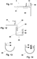
- FIG. 11 shows a dirty water supply profile 6 according to the invention, in which the anchoring leg 61 has recesses 80 which increase the surface area in sections on its underside facing the screed. These recesses enlarge the surface of the anchoring leg facing the screed and cause it to be secured by means of an adhesive, e.g. 8, anchoring leg to be fixed on the screed due to the now larger contact area.
- the bottom 81 of the dirty water supply channel is inclined obliquely downwards transversely to the longitudinal extent of the supply profile 6 towards the balcony. This inclination of the floor 81 instead of the fillet in the embodiment shown in Fig. 8 has the advantage that the outflowing dirty water in any case led to the side of the dirty water supply profile closer to the concrete support plate and then at its end on its balcony-facing side into the dirty water -Drain channel is directed.
- FIG. 12 shows a modified exemplary embodiment of an end profile 24 and a dirty water drainage channel according to FIG. 4c.
- the modified dirty water drainage channel 25 has in its channel inside an elongated groove-like depression 86 with a narrowed mouth that runs in the longitudinal direction of the channel.
- the depression 86 is provided on the side of the profile leg forming the outer wall of the U-shaped dirty water drain channel 25 facing away from the balcony and is formed by two rib-like strip sections 87, 88 formed on the dirty water drain channel 25 at an equal distance parallel to this side of the profile leg .
- a connecting bolt, not shown here, can be inserted into the recess 86 as already described in connection with FIG. 3.
- the formation of the groove-like depression 86 also has the advantage that a sealing strip, for example a metal sealing tape, to be glued over the abutting edge of two dirty water drainage channels 25 can be inserted at one end into the groove-like depression and is thus protected against the weather.
- a sealing strip for example a metal sealing tape
- Figure 13 shows a further embodiment of a separately manufactured and on a corresponding end profile, e.g. the end profile 24 according to FIG. 4c, attachable waste water drainage channel 95, in which the water-carrying channel part is designed in the form of a circular arc.
- a fastening section is provided at the end of the channel part which is circular in cross-section, facing the balcony and which, in the manner described above (see, for example, FIG. 5b), penetrates the narrowed mouth of a groove-like depression provided on a corresponding end profile Strip section 35 and a strip section 38 engaging in the groove-like recess.
- FIG. 14 shows a modification of the waste water drainage channel 95 according to FIG. 13, in which, in addition to the 4c, strip sections 35 and 38 serving for fastening to a corresponding end profile, for example an end profile according to FIG. 4c, an elongated groove-like depression 86 with a narrowed mouth extending in the longitudinal direction of the channel is provided in the channel longitudinal direction and is provided in the manner described above (see FIG. 12) is formed by two rib-like strip sections 87, 88 formed on the waste water drainage channel 95. If two short dirty water drainage channels 95 are to be connected in alignment to form a long channel, the channels can be aligned with one another in a particularly simple manner by inserting a connecting bar described in connection with FIG. 3 into the recesses 86 thereof.
Landscapes
- Engineering & Computer Science (AREA)
- Architecture (AREA)
- Civil Engineering (AREA)
- Structural Engineering (AREA)
- Floor Finish (AREA)
- Road Paving Structures (AREA)
- Diaphragms For Electromechanical Transducers (AREA)
- Paper (AREA)
- Control Of Motors That Do Not Use Commutators (AREA)
- Steps, Ramps, And Handrails (AREA)
Applications Claiming Priority (6)
| Application Number | Priority Date | Filing Date | Title |
|---|---|---|---|
| DE19503461 | 1995-02-03 | ||
| DE19503461 | 1995-02-03 | ||
| DE19506715 | 1995-02-27 | ||
| DE19506715 | 1995-02-27 | ||
| DE19508342A DE19508342C2 (de) | 1995-02-03 | 1995-03-09 | Entwässerungssystem für Balkone |
| DE19508342 | 1995-03-09 |
Publications (2)
| Publication Number | Publication Date |
|---|---|
| EP0725194A1 true EP0725194A1 (fr) | 1996-08-07 |
| EP0725194B1 EP0725194B1 (fr) | 1999-11-17 |
Family
ID=27214804
Family Applications (1)
| Application Number | Title | Priority Date | Filing Date |
|---|---|---|---|
| EP96101255A Expired - Lifetime EP0725194B1 (fr) | 1995-02-03 | 1996-01-30 | Dispositif de drainage pour balcons |
Country Status (4)
| Country | Link |
|---|---|
| EP (1) | EP0725194B1 (fr) |
| AT (1) | ATE186761T1 (fr) |
| DE (1) | DE29514797U1 (fr) |
| ES (1) | ES2139260T3 (fr) |
Cited By (2)
| Publication number | Priority date | Publication date | Assignee | Title |
|---|---|---|---|---|
| DE29620258U1 (de) * | 1996-02-06 | 1997-02-13 | Sks Stakusit Kunststoff Gmbh | Regenrinne |
| EP1635007A1 (fr) * | 2004-09-14 | 2006-03-15 | Richard Malcher | Profilé de bordure pour un balcon |
Families Citing this family (12)
| Publication number | Priority date | Publication date | Assignee | Title |
|---|---|---|---|---|
| EP0851958B1 (fr) * | 1995-09-22 | 1998-12-30 | SCHLÜTER SYSTEMS GmbH | Systeme de fixation de gouttieres aux extremites des balcons ou terrasses |
| DE29615229U1 (de) * | 1996-08-31 | 1998-01-08 | Gutjahr, Walter, 64404 Bickenbach | Abschlußprofilsystem für Balkone o.dgl. |
| DE19635852A1 (de) * | 1996-09-04 | 1998-03-05 | Walter Gutjahr | Abschlußprofil für mit Fliesen verlegte Balkone, Terrassen o. dgl. |
| DE29709627U1 (de) * | 1997-06-03 | 1998-10-08 | Gutjahr, Walter, 64404 Bickenbach | Abschlußprofil |
| DE19821785C2 (de) * | 1997-06-10 | 2000-07-06 | Baumjohann Adolf | Mehrteiliger Traufrandabschluß eines flach geneigten Terrassendaches |
| DE19724445C2 (de) * | 1997-06-10 | 1999-06-10 | Adolf Baumjohann | Mehrteiliger Dachrandabschluß an der Traufe eines flach geneigten Terrassendaches |
| DE19742571C1 (de) * | 1997-09-26 | 1999-03-25 | Franz Haederer | Betonplatte mit vertikaler Abdichtung |
| DE19915347C1 (de) * | 1999-04-06 | 2000-10-12 | Adolf Baumjohann | Dachrandabschluß eines flachgeneigten Daches |
| FR2800774A1 (fr) * | 1999-11-08 | 2001-05-11 | Daniel Sauvat | Dispositif d'evacuation des eaux de pluie pour balcons et terrasses |
| DE10200527C2 (de) * | 2002-01-09 | 2003-11-13 | R A B S Balkonbau Gmbh | Balkon |
| DE202007004298U1 (de) | 2007-03-13 | 2008-07-24 | Gutjahr, Walter | Abschlussprofilanordnung für Balkone, Terrassen u.dgl. mit Plattenbelägen |
| DE202007011416U1 (de) | 2007-08-16 | 2009-01-02 | Gutjahr, Walter | Abschlussprofilanordnung für Balkone, Terrassen u.dgl. |
Citations (7)
| Publication number | Priority date | Publication date | Assignee | Title |
|---|---|---|---|---|
| GB983080A (en) * | 1962-10-31 | 1965-02-10 | James Booth Aluminium Ltd | Improvements in roofing edge strips |
| GB2003538A (en) * | 1977-09-02 | 1979-03-14 | Redpath Dorman Long Ltd | Improvements in building construction |
| US4195452A (en) * | 1979-02-02 | 1980-04-01 | Clyde Grayum | Gutter and hanger arrangement |
| US4631875A (en) * | 1985-07-16 | 1986-12-30 | Eave-In-One, Inc. | Gutter assembly and method of installation |
| DE9004119U1 (de) * | 1990-04-09 | 1990-06-13 | Gutjahr, Walter, 6101 Bickenbach | Drain-Abschlußprofil |
| DE9007152U1 (de) * | 1990-06-28 | 1990-09-06 | Templin, Günter, 7990 Friedrichshafen | Balkonentwässerungs-Winkelleiste |
| DE8913663U1 (de) * | 1989-11-20 | 1991-03-21 | Münkel, Rudolf, 6419 Eiterfeld | Rinnen-Randprofil |
Family Cites Families (4)
| Publication number | Priority date | Publication date | Assignee | Title |
|---|---|---|---|---|
| DE7222201U (de) * | 1972-10-19 | Lange K | Randprofil für Balkone, Flachdächer od. dgl | |
| DE3407718A1 (de) * | 1984-03-02 | 1985-09-05 | Dynamit Nobel Ag, 5210 Troisdorf | Wintergarten |
| DE3841335A1 (de) * | 1988-12-08 | 1990-06-13 | Werner Schlueter | Leiste zum sichtabschluss des moertelbettes fuer fliesen- oder plattenbelaege |
| DE29504990U1 (de) * | 1995-03-24 | 1995-05-18 | Münkel, Rudolf, 36132 Eiterfeld | Traufen- und Verblendprofilelement für Balkon- und Terrassengrundplatten |
-
1995
- 1995-09-18 DE DE29514797U patent/DE29514797U1/de not_active Expired - Lifetime
-
1996
- 1996-01-30 EP EP96101255A patent/EP0725194B1/fr not_active Expired - Lifetime
- 1996-01-30 AT AT96101255T patent/ATE186761T1/de not_active IP Right Cessation
- 1996-01-30 ES ES96101255T patent/ES2139260T3/es not_active Expired - Lifetime
Patent Citations (7)
| Publication number | Priority date | Publication date | Assignee | Title |
|---|---|---|---|---|
| GB983080A (en) * | 1962-10-31 | 1965-02-10 | James Booth Aluminium Ltd | Improvements in roofing edge strips |
| GB2003538A (en) * | 1977-09-02 | 1979-03-14 | Redpath Dorman Long Ltd | Improvements in building construction |
| US4195452A (en) * | 1979-02-02 | 1980-04-01 | Clyde Grayum | Gutter and hanger arrangement |
| US4631875A (en) * | 1985-07-16 | 1986-12-30 | Eave-In-One, Inc. | Gutter assembly and method of installation |
| DE8913663U1 (de) * | 1989-11-20 | 1991-03-21 | Münkel, Rudolf, 6419 Eiterfeld | Rinnen-Randprofil |
| DE9004119U1 (de) * | 1990-04-09 | 1990-06-13 | Gutjahr, Walter, 6101 Bickenbach | Drain-Abschlußprofil |
| DE9007152U1 (de) * | 1990-06-28 | 1990-09-06 | Templin, Günter, 7990 Friedrichshafen | Balkonentwässerungs-Winkelleiste |
Cited By (2)
| Publication number | Priority date | Publication date | Assignee | Title |
|---|---|---|---|---|
| DE29620258U1 (de) * | 1996-02-06 | 1997-02-13 | Sks Stakusit Kunststoff Gmbh | Regenrinne |
| EP1635007A1 (fr) * | 2004-09-14 | 2006-03-15 | Richard Malcher | Profilé de bordure pour un balcon |
Also Published As
| Publication number | Publication date |
|---|---|
| DE29514797U1 (de) | 1996-06-05 |
| EP0725194B1 (fr) | 1999-11-17 |
| ES2139260T3 (es) | 2000-02-01 |
| ATE186761T1 (de) | 1999-12-15 |
Similar Documents
| Publication | Publication Date | Title |
|---|---|---|
| EP2025827A1 (fr) | Dispositif de profilé de fermeture pour balcons, terrasses et analogues | |
| EP0725194B1 (fr) | Dispositif de drainage pour balcons | |
| EP0828037B1 (fr) | Profilé de bordure pour balcons ou terrasses recouverts par des carreaux | |
| DE19535187C2 (de) | Befestigungssystem zum Anbringen von Rinnen an Balkon- oder Terrassenabschlüssen | |
| DE19508342C2 (de) | Entwässerungssystem für Balkone | |
| DE2139130A1 (de) | Fensterrahmen | |
| AT511661B1 (de) | Verbindungsanordnung von seitlich genuteten boden- oder wandbrettern | |
| DE3740470C2 (de) | Entwässerungsrinne und damit aufgebautes Rinnensystem | |
| DE102010045483A1 (de) | Verkleidungs- und Entwässerungselement für die Stirnseite von Bauteilen wie Balkone, Terrassen, Laubengänge, Flachdachränder und dergleichen | |
| DE19612505A1 (de) | Entwässerungssystem für Balkone mit Brüstung | |
| DE69702577T2 (de) | Ornamentale Stütze und Anlage für Fallrohre | |
| DE102016007242B4 (de) | Vorrichtung zum Abdecken des äußeren Bereichs der unteren Begrenzung einer Gebäudeöffnung | |
| EP3121359B1 (fr) | Système de fermeture lisse à rainure pré-monté | |
| EP1635007B1 (fr) | Profilé de bordure pour un balcon | |
| DE29802829U1 (de) | Überlaufrinne für Schwimmbecken | |
| EP0826849A2 (fr) | Système de profilé de bordure pour balcons ou similaires | |
| EP1970498B1 (fr) | Assemblage de profilés de bordure pour balcons, terrasses et similaires avec dalles | |
| EP1625266A1 (fr) | Revetement pour une surface telle qu'un balcon, un sol, un toit ou une facade | |
| DE102017131240A1 (de) | Abdeckung für eine Glasgeländervorrichtung | |
| AT8627U1 (de) | Einfassung für ein dach | |
| DE202010008161U1 (de) | Entwässerungssystem für Balkonplatten | |
| DE20001303U1 (de) | Ablaufrinne, insbesondere für Balkon- oder Terrassenabschlüsse | |
| AT11495U1 (de) | Abdeckelement für einen fensterbank-seitenabschluss | |
| CH720018A2 (de) | Wanddurchführungseinheit und Außenwandgitter mit einer Abtropfleiste | |
| DE2428003C2 (de) | Dichtungsprofil für unterhalb von Fenstersohlbanken, Artiken o.dgl. befindliche Horizontalfugen |
Legal Events
| Date | Code | Title | Description |
|---|---|---|---|
| PUAI | Public reference made under article 153(3) epc to a published international application that has entered the european phase |
Free format text: ORIGINAL CODE: 0009012 |
|
| AK | Designated contracting states |
Kind code of ref document: A1 Designated state(s): AT BE CH DE DK ES FR GB IT LI LU NL SE |
|
| 17P | Request for examination filed |
Effective date: 19961121 |
|
| 17Q | First examination report despatched |
Effective date: 19981012 |
|
| GRAG | Despatch of communication of intention to grant |
Free format text: ORIGINAL CODE: EPIDOS AGRA |
|
| GRAG | Despatch of communication of intention to grant |
Free format text: ORIGINAL CODE: EPIDOS AGRA |
|
| GRAH | Despatch of communication of intention to grant a patent |
Free format text: ORIGINAL CODE: EPIDOS IGRA |
|
| GRAH | Despatch of communication of intention to grant a patent |
Free format text: ORIGINAL CODE: EPIDOS IGRA |
|
| GRAA | (expected) grant |
Free format text: ORIGINAL CODE: 0009210 |
|
| RAP3 | Party data changed (applicant data changed or rights of an application transferred) |
Owner name: GUTJAHR, WALTER |
|
| RIN1 | Information on inventor provided before grant (corrected) |
Inventor name: GUTJAHR, WALTER |
|
| AK | Designated contracting states |
Kind code of ref document: B1 Designated state(s): AT BE CH DE DK ES FR GB IT LI LU NL SE |
|
| PG25 | Lapsed in a contracting state [announced via postgrant information from national office to epo] |
Ref country code: NL Free format text: LAPSE BECAUSE OF FAILURE TO SUBMIT A TRANSLATION OF THE DESCRIPTION OR TO PAY THE FEE WITHIN THE PRESCRIBED TIME-LIMIT Effective date: 19991117 |
|
| REF | Corresponds to: |
Ref document number: 186761 Country of ref document: AT Date of ref document: 19991215 Kind code of ref document: T |
|
| REG | Reference to a national code |
Ref country code: CH Ref legal event code: EP |
|
| GBT | Gb: translation of ep patent filed (gb section 77(6)(a)/1977) |
Effective date: 19991117 |
|
| REF | Corresponds to: |
Ref document number: 59603645 Country of ref document: DE Date of ref document: 19991223 |
|
| PGFP | Annual fee paid to national office [announced via postgrant information from national office to epo] |
Ref country code: SE Payment date: 20000110 Year of fee payment: 5 |
|
| PGFP | Annual fee paid to national office [announced via postgrant information from national office to epo] |
Ref country code: CH Payment date: 20000119 Year of fee payment: 5 |
|
| PGFP | Annual fee paid to national office [announced via postgrant information from national office to epo] |
Ref country code: GB Payment date: 20000126 Year of fee payment: 5 |
|
| ITF | It: translation for a ep patent filed | ||
| PG25 | Lapsed in a contracting state [announced via postgrant information from national office to epo] |
Ref country code: LU Free format text: LAPSE BECAUSE OF NON-PAYMENT OF DUE FEES Effective date: 20000130 |
|
| PG25 | Lapsed in a contracting state [announced via postgrant information from national office to epo] |
Ref country code: ES Free format text: LAPSE BECAUSE OF NON-PAYMENT OF DUE FEES Effective date: 20000131 |
|
| REG | Reference to a national code |
Ref country code: ES Ref legal event code: FG2A Ref document number: 2139260 Country of ref document: ES Kind code of ref document: T3 |
|
| REG | Reference to a national code |
Ref country code: CH Ref legal event code: NV Representative=s name: BOVARD AG PATENTANWAELTE |
|
| PG25 | Lapsed in a contracting state [announced via postgrant information from national office to epo] |
Ref country code: DK Free format text: LAPSE BECAUSE OF FAILURE TO SUBMIT A TRANSLATION OF THE DESCRIPTION OR TO PAY THE FEE WITHIN THE PRESCRIBED TIME-LIMIT Effective date: 20000217 |
|
| ET | Fr: translation filed | ||
| NLV1 | Nl: lapsed or annulled due to failure to fulfill the requirements of art. 29p and 29m of the patents act | ||
| PLBE | No opposition filed within time limit |
Free format text: ORIGINAL CODE: 0009261 |
|
| STAA | Information on the status of an ep patent application or granted ep patent |
Free format text: STATUS: NO OPPOSITION FILED WITHIN TIME LIMIT |
|
| 26N | No opposition filed | ||
| PG25 | Lapsed in a contracting state [announced via postgrant information from national office to epo] |
Ref country code: GB Free format text: LAPSE BECAUSE OF NON-PAYMENT OF DUE FEES Effective date: 20010130 |
|
| PG25 | Lapsed in a contracting state [announced via postgrant information from national office to epo] |
Ref country code: SE Free format text: LAPSE BECAUSE OF NON-PAYMENT OF DUE FEES Effective date: 20010131 Ref country code: LI Free format text: LAPSE BECAUSE OF NON-PAYMENT OF DUE FEES Effective date: 20010131 Ref country code: CH Free format text: LAPSE BECAUSE OF NON-PAYMENT OF DUE FEES Effective date: 20010131 |
|
| EUG | Se: european patent has lapsed |
Ref document number: 96101255.6 |
|
| REG | Reference to a national code |
Ref country code: CH Ref legal event code: PL |
|
| GBPC | Gb: european patent ceased through non-payment of renewal fee |
Effective date: 20010130 |
|
| PGFP | Annual fee paid to national office [announced via postgrant information from national office to epo] |
Ref country code: FR Payment date: 20030129 Year of fee payment: 8 |
|
| PGFP | Annual fee paid to national office [announced via postgrant information from national office to epo] |
Ref country code: BE Payment date: 20030204 Year of fee payment: 8 |
|
| PG25 | Lapsed in a contracting state [announced via postgrant information from national office to epo] |
Ref country code: BE Free format text: LAPSE BECAUSE OF NON-PAYMENT OF DUE FEES Effective date: 20040131 |
|
| REG | Reference to a national code |
Ref country code: ES Ref legal event code: FD2A Effective date: 20010210 |
|
| BERE | Be: lapsed |
Owner name: *GUTJAHR WALTER Effective date: 20040131 |
|
| PG25 | Lapsed in a contracting state [announced via postgrant information from national office to epo] |
Ref country code: FR Free format text: LAPSE BECAUSE OF NON-PAYMENT OF DUE FEES Effective date: 20040930 |
|
| REG | Reference to a national code |
Ref country code: FR Ref legal event code: ST |
|
| PG25 | Lapsed in a contracting state [announced via postgrant information from national office to epo] |
Ref country code: IT Free format text: LAPSE BECAUSE OF NON-PAYMENT OF DUE FEES Effective date: 20050130 |
|
| PGFP | Annual fee paid to national office [announced via postgrant information from national office to epo] |
Ref country code: AT Payment date: 20080114 Year of fee payment: 13 |
|
| PG25 | Lapsed in a contracting state [announced via postgrant information from national office to epo] |
Ref country code: AT Free format text: LAPSE BECAUSE OF NON-PAYMENT OF DUE FEES Effective date: 20090130 |
|
| PGFP | Annual fee paid to national office [announced via postgrant information from national office to epo] |
Ref country code: DE Payment date: 20141211 Year of fee payment: 20 |
|
| REG | Reference to a national code |
Ref country code: DE Ref legal event code: R082 Ref document number: 59603645 Country of ref document: DE Representative=s name: PATENTANWAELTE KATSCHER HABERMANN, DE Ref country code: DE Ref legal event code: R081 Ref document number: 59603645 Country of ref document: DE Owner name: ARDEX ANLAGEN GMBH, DE Free format text: FORMER OWNER: GUTJAHR, WALTER, 64404 BICKENBACH, DE |
|
| REG | Reference to a national code |
Ref country code: DE Ref legal event code: R071 Ref document number: 59603645 Country of ref document: DE |