EP0725264A2 - Machine de détection de joints défectueux dans des récipients à gaz pressurisé - Google Patents
Machine de détection de joints défectueux dans des récipients à gaz pressurisé Download PDFInfo
- Publication number
- EP0725264A2 EP0725264A2 EP96500016A EP96500016A EP0725264A2 EP 0725264 A2 EP0725264 A2 EP 0725264A2 EP 96500016 A EP96500016 A EP 96500016A EP 96500016 A EP96500016 A EP 96500016A EP 0725264 A2 EP0725264 A2 EP 0725264A2
- Authority
- EP
- European Patent Office
- Prior art keywords
- mentioned
- containers
- container
- faulty
- joint
- Prior art date
- Legal status (The legal status is an assumption and is not a legal conclusion. Google has not performed a legal analysis and makes no representation as to the accuracy of the status listed.)
- Granted
Links
Images


Classifications
-
- G—PHYSICS
- G01—MEASURING; TESTING
- G01M—TESTING STATIC OR DYNAMIC BALANCE OF MACHINES OR STRUCTURES; TESTING OF STRUCTURES OR APPARATUS, NOT OTHERWISE PROVIDED FOR
- G01M3/00—Investigating fluid-tightness of structures
- G01M3/02—Investigating fluid-tightness of structures by using fluid or vacuum
- G01M3/26—Investigating fluid-tightness of structures by using fluid or vacuum by measuring rate of loss or gain of fluid, e.g. by pressure-responsive devices, by flow detectors
- G01M3/32—Investigating fluid-tightness of structures by using fluid or vacuum by measuring rate of loss or gain of fluid, e.g. by pressure-responsive devices, by flow detectors for containers, e.g. radiators
- G01M3/3236—Investigating fluid-tightness of structures by using fluid or vacuum by measuring rate of loss or gain of fluid, e.g. by pressure-responsive devices, by flow detectors for containers, e.g. radiators by monitoring the interior space of the containers
-
- G—PHYSICS
- G01—MEASURING; TESTING
- G01M—TESTING STATIC OR DYNAMIC BALANCE OF MACHINES OR STRUCTURES; TESTING OF STRUCTURES OR APPARATUS, NOT OTHERWISE PROVIDED FOR
- G01M3/00—Investigating fluid-tightness of structures
- G01M3/02—Investigating fluid-tightness of structures by using fluid or vacuum
- G01M3/26—Investigating fluid-tightness of structures by using fluid or vacuum by measuring rate of loss or gain of fluid, e.g. by pressure-responsive devices, by flow detectors
- G01M3/32—Investigating fluid-tightness of structures by using fluid or vacuum by measuring rate of loss or gain of fluid, e.g. by pressure-responsive devices, by flow detectors for containers, e.g. radiators
- G01M3/3209—Details, e.g. container closure devices
Definitions
- the object of the present Utility Model is constituted by a FAULTY JOINTS DETECTING MACHINE IN PRESSURIZED GAS CONTAINERS, specially applicable to the detention of faults originated as consequence of the use, or for any other reason, in the sealing joints of the oil liquefied gas containers.
- the invention has developed a machine that favourably solve the problem raised, supposing an important novelty in reference to the methods used, bringing forward the automatic verification means not only for the mentioned joint but also for some faults that may affect the gas outlet valve itself.
- the machine suggested by the present invention starts up with the preferably automatic feeding of the containers, by means of a conveyor belt or line.
- the position of the containers which joint has to be verified is being detected by a set of sensors conveniently distributed along their run, in such a way that the mentioned sensors act on the braking/release means of each container both at the beginning of the cycle as well as when it reaches the joint verification position.
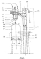
- the machine itself is constructed starting from a support structure, preferably metallic, on which it is arranged a platform equipped with guiding means of lowering/rising movable device which comprises a support base with two shafts in diametrically opposed positions to which an analysis bell is held in a lower position against the action of both springs.
- the above mentioned analysis bell is susceptible of receiving in the inside the valve of the container properly positioned under the same, reproducing the working conditions in which such gas container usually is subjected to when is being used by the user, in such a way that the measured degree of sealing between such belt and such valve determines whether the joint is faulty or not, by which after a predetermined period of time has passed, the analysis bell is withdrawn and the container in question is sent by the rejection route or by the one of acceptance according to the result of the measuring carried out.
- the invention has foreseen testing pressure regulating means and the period of time that has to pass in each one of the foreseen operations.
- the shaft (11) of the cylinder (4) is jointly held to the support base (3) by nuts (12) and through an appropriate support conical piece (13).
- the support base (3) is oriented in its lowering/raising displacement by two lateral shafts (14) housed in cylindrical guiding elements (15) which at the same time have bearings (16) inside which facilitate the displacement of such shafts (14).
- the bell (8) easily reproduces the coupling and sealing conditions between the regulator of domestic use and the container valve, in such a way that the internal chamber of the bell is supplied with a given pressure, during an specific period of time, through the duct (22) and the sealing conditions are analyzed. If after this period of time it is not produced any drop in the pressure value, the sealing of the joint is ensured and the movable assembly is displaced upwardly, dragged by the cylinder (4), by which the valve (18) of the container (17) is liberated.
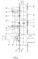
- the braking device (20) is withdrawn driven by the cylinder (21) associated thereof, and the container (17) is dragged by the conveyor belt (19) in the direction of the valid containers, passing a second container to occupy the position of the previous one to be submitted to the same test, starting the cycle again.
- the first container (25) will have reached the analysis position (17), activating a sensor (30) and being retained in such position by the brake (26), while a second container will be in the position (28), in a stand by condition, retained by the first container (17).
- the distance between both already mentioned brakes (26) and (20) will be such that allows the placing of two containers in the way represented in the drawing.
- the machine will have at the same time a conventional circuit breaker for the functions of cycle/emergency, which are not represented. After manually acting on this circuit breaker and regulating it to the "cycle” position and activating a "starting cycle” push bottom not shown, it will start the verification automatic sequence of the state of the joint (24) as it has been explained in reference to Figures 1 to 3.
- the movable assembly will rise driven by the cylinder (4), activating a sensor in its run (32) which will generate the opening command of the brake device (20) by which the container (17) is liberated and dragged by the conveyor belt, in such a way that the container (28) which was in the stand by condition will occupy the position in which the container was placed (17) for the analysis of the respective joint.
- This new container will be equally retained by the braking device (20) since when the container (17) is dragged by the conveyor belt will activate a sensor (31) placed immediately after such brake (20), restarting again all the described cycle at the time that the new container, on arriving to the analysis position, activates the sensor (30).
- the containers in which the state of the joint were verified and are correct, are transported by the conveyor belt in the direction pointed out by the arrow B.
- the container with faulty joint which was liberated will reach in its run the position of a sensor (33) which will verify the situation of this container against an expelling device formed by a cylinder (34) and a pushing arm (35).
- the cylinder (34) will extend the pushing arm (35) in order to divert such faulty container towards another conveyor belt in the direction of the arrow C.
- the braking device (20) is extended and the whole cycle remains inhibited until the pushing arm is withdrawn to its resting position, this condition is detected by a sensor (36), at that time the whole cycle starts again.
- the assembly will eventually have available the detection means for possible blockage in the outlet of the conveyor belt, which preferably will consist of a sensor (37) located in a predetermined position along the run of the containers according to the direction B, such as when this sensor is activated by one of the containers during a preestablished time, all the cycle remains inhibited, restarting again only after such sensor (37) has been deactivated.
- a sensor located in a predetermined position along the run of the containers according to the direction B, such as when this sensor is activated by one of the containers during a preestablished time, all the cycle remains inhibited, restarting again only after such sensor (37) has been deactivated.
- the unit includes a pulse counter with manual regulation to zero, preferably of pneumatic type, placed in a given position along the path C, with the purpose of counting the number of faulty containers which are rejected by the machine.
- the machine will also incorporate other devices such as pressure regulators, manometers, timers, etc., intended to establish and control the working conditions thereof, and which are not described because they are of conventional type.
- the cylinder used can be of pneumatic or hydraulic type, according to the requirements of each particular case.
Landscapes
- Physics & Mathematics (AREA)
- General Physics & Mathematics (AREA)
- Examining Or Testing Airtightness (AREA)
- Filling Or Discharging Of Gas Storage Vessels (AREA)
- Filling Of Jars Or Cans And Processes For Cleaning And Sealing Jars (AREA)
- Gas-Insulated Switchgears (AREA)
- Measuring Fluid Pressure (AREA)
Applications Claiming Priority (2)
| Application Number | Priority Date | Filing Date | Title |
|---|---|---|---|
| ES09500328U ES1030100Y (es) | 1995-02-06 | 1995-02-06 | Maquina detectora de juntas defectuosas en envases contenedores de gases a presion. |
| ES9500328 | 1995-02-06 |
Publications (3)
| Publication Number | Publication Date |
|---|---|
| EP0725264A2 true EP0725264A2 (fr) | 1996-08-07 |
| EP0725264A3 EP0725264A3 (fr) | 1998-04-01 |
| EP0725264B1 EP0725264B1 (fr) | 2002-06-05 |
Family
ID=8289524
Family Applications (1)
| Application Number | Title | Priority Date | Filing Date |
|---|---|---|---|
| EP96500016A Expired - Lifetime EP0725264B1 (fr) | 1995-02-06 | 1996-02-02 | Machine de détection de joints défectueux dans des récipients à gaz pressurisé |
Country Status (5)
| Country | Link |
|---|---|
| EP (1) | EP0725264B1 (fr) |
| AT (1) | ATE218703T1 (fr) |
| DE (1) | DE69621477D1 (fr) |
| ES (1) | ES1030100Y (fr) |
| PT (1) | PT725264E (fr) |
Cited By (4)
| Publication number | Priority date | Publication date | Assignee | Title |
|---|---|---|---|---|
| EP0780191A1 (fr) * | 1995-12-22 | 1997-06-25 | Repsol Butano, S.A. | Machine pour monter des joints, utilisée de préférence pour récipients à gaz pressurisé |
| CN106012141A (zh) * | 2016-06-30 | 2016-10-12 | 成都启立辰智科技有限公司 | 平底锭子油位测量器 |
| CN108918121A (zh) * | 2018-07-10 | 2018-11-30 | 安徽悦众车身装备有限公司 | 一种汽车用气缸换气口排气性能检测装置 |
| CN111632878A (zh) * | 2020-07-20 | 2020-09-08 | 佛山市顺德区力扬奥特自动化设备有限公司 | 检测产品气密性的检漏机 |
Family Cites Families (2)
| Publication number | Priority date | Publication date | Assignee | Title |
|---|---|---|---|---|
| AU449169B2 (en) * | 1968-10-23 | 1974-05-16 | Owens-Illinois, Inc | Leak detector |
| FR2458064A1 (fr) * | 1979-05-29 | 1980-12-26 | Elf Antargaz | Procede et installation pour detecter les fuites sur des recipients contenant un fluide gazeux sous pression, notamment un gaz de petrole liquefie |
-
1995
- 1995-02-06 ES ES09500328U patent/ES1030100Y/es not_active Expired - Fee Related
-
1996
- 1996-02-02 AT AT96500016T patent/ATE218703T1/de not_active IP Right Cessation
- 1996-02-02 DE DE69621477T patent/DE69621477D1/de not_active Expired - Lifetime
- 1996-02-02 EP EP96500016A patent/EP0725264B1/fr not_active Expired - Lifetime
- 1996-02-02 PT PT96500016T patent/PT725264E/pt unknown
Cited By (5)
| Publication number | Priority date | Publication date | Assignee | Title |
|---|---|---|---|---|
| EP0780191A1 (fr) * | 1995-12-22 | 1997-06-25 | Repsol Butano, S.A. | Machine pour monter des joints, utilisée de préférence pour récipients à gaz pressurisé |
| CN106012141A (zh) * | 2016-06-30 | 2016-10-12 | 成都启立辰智科技有限公司 | 平底锭子油位测量器 |
| CN108918121A (zh) * | 2018-07-10 | 2018-11-30 | 安徽悦众车身装备有限公司 | 一种汽车用气缸换气口排气性能检测装置 |
| CN108918121B (zh) * | 2018-07-10 | 2019-12-03 | 安徽悦众车身装备有限公司 | 一种汽车用气缸换气口排气性能检测装置 |
| CN111632878A (zh) * | 2020-07-20 | 2020-09-08 | 佛山市顺德区力扬奥特自动化设备有限公司 | 检测产品气密性的检漏机 |
Also Published As
| Publication number | Publication date |
|---|---|
| DE69621477D1 (de) | 2002-07-11 |
| ES1030100Y (es) | 1996-01-01 |
| EP0725264B1 (fr) | 2002-06-05 |
| PT725264E (pt) | 2002-10-31 |
| ES1030100U (es) | 1995-07-16 |
| EP0725264A3 (fr) | 1998-04-01 |
| ATE218703T1 (de) | 2002-06-15 |
Similar Documents
| Publication | Publication Date | Title |
|---|---|---|
| EP0377264B1 (fr) | Système pour la détection des fuites | |
| US4517827A (en) | Apparatus and method for testing for leakages in hermetically-sealed packages | |
| US4862732A (en) | Leak testing | |
| US4426683A (en) | Pneumatic shock testing machine with digital control | |
| US4470265A (en) | Refrigerant charging system | |
| CN106053243B (zh) | 智能型转盘式液化石油气钢瓶水压试验快速检测线 | |
| US4582102A (en) | Means for electronically comparing the extent of fill in containers with a preset extent | |
| US4184362A (en) | Bottle leak tester | |
| US4490800A (en) | Dual head gauger apparatus with automatic adjustment for pressure variation | |
| US4858463A (en) | Process and apparatus for detecting leaks in sealed packages | |
| US3874226A (en) | Bottle sorting apparatus | |
| EP0725264B1 (fr) | Machine de détection de joints défectueux dans des récipients à gaz pressurisé | |
| US3221539A (en) | Method and apparatus for leak testing castings | |
| CA2130949A1 (fr) | Appareil servant a detecter les fuites dans un contenant, en particulier dans une bouteile de plastique, et methode connexe | |
| US3584500A (en) | Fluid leakage test method and system | |
| US6623230B1 (en) | Can seam forming apparatus | |
| JP2875829B2 (ja) | 安全弁自動検査装置の精度確認装置 | |
| US3914872A (en) | Dual plug gauger | |
| US4495797A (en) | Can end tester | |
| US4667708A (en) | Method and apparatus for filling tanks with liquified gas | |
| EP3827240B1 (fr) | Dispositif et procédé de test d'étanchéité automatisé et d'inertisation de récipients ou de réceptacles similaires ayant un couvercle et/ou une soupape | |
| US3132508A (en) | Pressure tester and rejecter | |
| US3195724A (en) | Machine for testing sealed cans and for rejecting defective cans | |
| US3650145A (en) | Method and apparatus for testing hermetically-sealed containers | |
| US3313143A (en) | Apparatus for leak testing castings |
Legal Events
| Date | Code | Title | Description |
|---|---|---|---|
| PUAI | Public reference made under article 153(3) epc to a published international application that has entered the european phase |
Free format text: ORIGINAL CODE: 0009012 |
|
| AK | Designated contracting states |
Kind code of ref document: A2 Designated state(s): AT BE CH DE DK FR GB GR IE IT LI NL PT SE |
|
| PUAL | Search report despatched |
Free format text: ORIGINAL CODE: 0009013 |
|
| AK | Designated contracting states |
Kind code of ref document: A3 Designated state(s): AT BE CH DE DK FR GB GR IE IT LI NL PT SE |
|
| 17P | Request for examination filed |
Effective date: 19980925 |
|
| 17Q | First examination report despatched |
Effective date: 20010611 |
|
| GRAG | Despatch of communication of intention to grant |
Free format text: ORIGINAL CODE: EPIDOS AGRA |
|
| GRAG | Despatch of communication of intention to grant |
Free format text: ORIGINAL CODE: EPIDOS AGRA |
|
| GRAH | Despatch of communication of intention to grant a patent |
Free format text: ORIGINAL CODE: EPIDOS IGRA |
|
| GRAH | Despatch of communication of intention to grant a patent |
Free format text: ORIGINAL CODE: EPIDOS IGRA |
|
| GRAA | (expected) grant |
Free format text: ORIGINAL CODE: 0009210 |
|
| AK | Designated contracting states |
Kind code of ref document: B1 Designated state(s): AT BE CH DE DK FR GB GR IE IT LI NL PT SE |
|
| PG25 | Lapsed in a contracting state [announced via postgrant information from national office to epo] |
Ref country code: NL Free format text: LAPSE BECAUSE OF FAILURE TO SUBMIT A TRANSLATION OF THE DESCRIPTION OR TO PAY THE FEE WITHIN THE PRESCRIBED TIME-LIMIT Effective date: 20020605 Ref country code: LI Free format text: LAPSE BECAUSE OF FAILURE TO SUBMIT A TRANSLATION OF THE DESCRIPTION OR TO PAY THE FEE WITHIN THE PRESCRIBED TIME-LIMIT Effective date: 20020605 Ref country code: GR Free format text: LAPSE BECAUSE OF FAILURE TO SUBMIT A TRANSLATION OF THE DESCRIPTION OR TO PAY THE FEE WITHIN THE PRESCRIBED TIME-LIMIT Effective date: 20020605 Ref country code: CH Free format text: LAPSE BECAUSE OF FAILURE TO SUBMIT A TRANSLATION OF THE DESCRIPTION OR TO PAY THE FEE WITHIN THE PRESCRIBED TIME-LIMIT Effective date: 20020605 Ref country code: BE Free format text: LAPSE BECAUSE OF FAILURE TO SUBMIT A TRANSLATION OF THE DESCRIPTION OR TO PAY THE FEE WITHIN THE PRESCRIBED TIME-LIMIT Effective date: 20020605 Ref country code: AT Free format text: LAPSE BECAUSE OF FAILURE TO SUBMIT A TRANSLATION OF THE DESCRIPTION OR TO PAY THE FEE WITHIN THE PRESCRIBED TIME-LIMIT Effective date: 20020605 |
|
| REF | Corresponds to: |
Ref document number: 218703 Country of ref document: AT Date of ref document: 20020615 Kind code of ref document: T |
|
| REG | Reference to a national code |
Ref country code: GB Ref legal event code: FG4D |
|
| REG | Reference to a national code |
Ref country code: CH Ref legal event code: EP |
|
| REG | Reference to a national code |
Ref country code: IE Ref legal event code: FG4D |
|
| REF | Corresponds to: |
Ref document number: 69621477 Country of ref document: DE Date of ref document: 20020711 |
|
| ET | Fr: translation filed | ||
| PG25 | Lapsed in a contracting state [announced via postgrant information from national office to epo] |
Ref country code: SE Free format text: LAPSE BECAUSE OF FAILURE TO SUBMIT A TRANSLATION OF THE DESCRIPTION OR TO PAY THE FEE WITHIN THE PRESCRIBED TIME-LIMIT Effective date: 20020905 Ref country code: DK Free format text: LAPSE BECAUSE OF FAILURE TO SUBMIT A TRANSLATION OF THE DESCRIPTION OR TO PAY THE FEE WITHIN THE PRESCRIBED TIME-LIMIT Effective date: 20020905 |
|
| PG25 | Lapsed in a contracting state [announced via postgrant information from national office to epo] |
Ref country code: DE Free format text: LAPSE BECAUSE OF FAILURE TO SUBMIT A TRANSLATION OF THE DESCRIPTION OR TO PAY THE FEE WITHIN THE PRESCRIBED TIME-LIMIT Effective date: 20020906 |
|
| REG | Reference to a national code |
Ref country code: PT Ref legal event code: SC4A Free format text: AVAILABILITY OF NATIONAL TRANSLATION Effective date: 20020730 |
|
| NLV1 | Nl: lapsed or annulled due to failure to fulfill the requirements of art. 29p and 29m of the patents act | ||
| REG | Reference to a national code |
Ref country code: CH Ref legal event code: PL |
|
| PG25 | Lapsed in a contracting state [announced via postgrant information from national office to epo] |
Ref country code: GB Free format text: LAPSE BECAUSE OF NON-PAYMENT OF DUE FEES Effective date: 20030202 |
|
| PG25 | Lapsed in a contracting state [announced via postgrant information from national office to epo] |
Ref country code: IE Free format text: LAPSE BECAUSE OF NON-PAYMENT OF DUE FEES Effective date: 20030203 |
|
| PLBE | No opposition filed within time limit |
Free format text: ORIGINAL CODE: 0009261 |
|
| STAA | Information on the status of an ep patent application or granted ep patent |
Free format text: STATUS: NO OPPOSITION FILED WITHIN TIME LIMIT |
|
| 26N | No opposition filed |
Effective date: 20030306 |
|
| GBPC | Gb: european patent ceased through non-payment of renewal fee | ||
| REG | Reference to a national code |
Ref country code: IE Ref legal event code: MM4A |
|
| PGFP | Annual fee paid to national office [announced via postgrant information from national office to epo] |
Ref country code: IT Payment date: 20070620 Year of fee payment: 12 |
|
| PGFP | Annual fee paid to national office [announced via postgrant information from national office to epo] |
Ref country code: PT Payment date: 20080130 Year of fee payment: 13 |
|
| PGFP | Annual fee paid to national office [announced via postgrant information from national office to epo] |
Ref country code: FR Payment date: 20080222 Year of fee payment: 13 |
|
| REG | Reference to a national code |
Ref country code: PT Ref legal event code: MM4A Free format text: LAPSE DUE TO NON-PAYMENT OF FEES Effective date: 20090803 |
|
| PG25 | Lapsed in a contracting state [announced via postgrant information from national office to epo] |
Ref country code: IT Free format text: LAPSE BECAUSE OF NON-PAYMENT OF DUE FEES Effective date: 20080202 |
|
| PG25 | Lapsed in a contracting state [announced via postgrant information from national office to epo] |
Ref country code: PT Free format text: LAPSE BECAUSE OF NON-PAYMENT OF DUE FEES Effective date: 20090803 |
|
| REG | Reference to a national code |
Ref country code: FR Ref legal event code: ST Effective date: 20091030 |
|
| PG25 | Lapsed in a contracting state [announced via postgrant information from national office to epo] |
Ref country code: FR Free format text: LAPSE BECAUSE OF NON-PAYMENT OF DUE FEES Effective date: 20090302 |