EP0725487A2 - Mehrpegelkodierung für fraktionelle Bits - Google Patents
Mehrpegelkodierung für fraktionelle Bits Download PDFInfo
- Publication number
- EP0725487A2 EP0725487A2 EP96300482A EP96300482A EP0725487A2 EP 0725487 A2 EP0725487 A2 EP 0725487A2 EP 96300482 A EP96300482 A EP 96300482A EP 96300482 A EP96300482 A EP 96300482A EP 0725487 A2 EP0725487 A2 EP 0725487A2
- Authority
- EP
- European Patent Office
- Prior art keywords
- bits
- symbols
- encoder
- code
- mapper
- Prior art date
- Legal status (The legal status is an assumption and is not a legal conclusion. Google has not performed a legal analysis and makes no representation as to the accuracy of the status listed.)
- Withdrawn
Links
Images




Classifications
-
- H—ELECTRICITY
- H03—ELECTRONIC CIRCUITRY
- H03M—CODING; DECODING; CODE CONVERSION IN GENERAL
- H03M1/00—Analogue/digital conversion; Digital/analogue conversion
- H03M1/12—Analogue/digital converters
-
- H—ELECTRICITY
- H03—ELECTRONIC CIRCUITRY
- H03M—CODING; DECODING; CODE CONVERSION IN GENERAL
- H03M13/00—Coding, decoding or code conversion, for error detection or error correction; Coding theory basic assumptions; Coding bounds; Error probability evaluation methods; Channel models; Simulation or testing of codes
- H03M13/03—Error detection or forward error correction by redundancy in data representation, i.e. code words containing more digits than the source words
- H03M13/23—Error detection or forward error correction by redundancy in data representation, i.e. code words containing more digits than the source words using convolutional codes, e.g. unit memory codes
-
- H—ELECTRICITY
- H04—ELECTRIC COMMUNICATION TECHNIQUE
- H04L—TRANSMISSION OF DIGITAL INFORMATION, e.g. TELEGRAPHIC COMMUNICATION
- H04L25/00—Baseband systems
- H04L25/02—Details ; arrangements for supplying electrical power along data transmission lines
- H04L25/03—Shaping networks in transmitter or receiver, e.g. adaptive shaping networks
- H04L25/03006—Arrangements for removing intersymbol interference
- H04L25/03343—Arrangements at the transmitter end
-
- H—ELECTRICITY
- H04—ELECTRIC COMMUNICATION TECHNIQUE
- H04L—TRANSMISSION OF DIGITAL INFORMATION, e.g. TELEGRAPHIC COMMUNICATION
- H04L25/00—Baseband systems
- H04L25/38—Synchronous or start-stop systems, e.g. for Baudot code
- H04L25/40—Transmitting circuits; Receiving circuits
- H04L25/49—Transmitting circuits; Receiving circuits using code conversion at the transmitter; using predistortion; using insertion of idle bits for obtaining a desired frequency spectrum; using three or more amplitude levels ; Baseband coding techniques specific to data transmission systems
- H04L25/4917—Transmitting circuits; Receiving circuits using code conversion at the transmitter; using predistortion; using insertion of idle bits for obtaining a desired frequency spectrum; using three or more amplitude levels ; Baseband coding techniques specific to data transmission systems using multilevel codes
- H04L25/4927—Transmitting circuits; Receiving circuits using code conversion at the transmitter; using predistortion; using insertion of idle bits for obtaining a desired frequency spectrum; using three or more amplitude levels ; Baseband coding techniques specific to data transmission systems using multilevel codes using levels matched to the quantisation levels of the channel
-
- H—ELECTRICITY
- H04—ELECTRIC COMMUNICATION TECHNIQUE
- H04L—TRANSMISSION OF DIGITAL INFORMATION, e.g. TELEGRAPHIC COMMUNICATION
- H04L1/00—Arrangements for detecting or preventing errors in the information received
- H04L2001/0098—Unequal error protection
Definitions
- This invention relates to coding.
- Modems communicate digital data over an analog communication medium by mapping the data onto analog signals.
- Some of today's sophisticated modems communicate digital information by mapping the data onto analog signals and, thereafter, modulating an analog carrier with those signals.
- a collection of bits are combined to form a two-dimensional symbol, the symbol components are converted to analog form, and the analog-form components respectively modulate a carrier and a quadrature replica of the carrier.
- the two modulation products are added and filtered, and the result is applied to the transmission medium.
- a remote modem receives the signal, samples it, identifies the magnitudes and phases of the analog samples, converts the samples to symbols, and finally recovers the original bits of data. What these modems do, in effect, is encode the digital signals onto a two dimensional symbol constellation that is modulated onto a carrier.
- the primary sources of error are signal echoes from imperfect hybrids and other discontinuities in the transmission lines, as well as noise from a myriad of unknown sources.
- the telecommunication network includes digital links, where the analog data is sampled and quantized, an additional noise source is introduced that is rooted in the sampling and quantization that occurs at the network.
- Efficient encoding of symbols is realized with multilevel encoding, where components of the symbols that are more susceptible to errors are encoded more robustly than components that are less susceptible to error.
- a non-binary constellation of symbols is handled with a fractional bit rate converter that combines with the multilevel encoder to create an effective and efficient constellation of symbols.
- digital data applied to a modem is encoded and mapped onto a subset of the levels recognized by a central office codec, with the two least significant bits in the binary representation of the levels delivered by the modem having been encoded with a multi-level code.
- the least significant bit is encoded with a code that is more robust than the code of the next-to-least significant bit, in recognition of the fact that errors in the least significant bit are much more likely.
- the most significant bits are mapped with the aid of a fractional bit rate mapper that optimizes a selected aspect of the symbol constellation, such as average power.
- the corresponding echo canceller in the network first estimates the echo and subtracts it from the signal applied to the digital network by the central office.
- the least significant bit of symbols is identified based on a first error correcting code.
- the remaining bits of the symbols are determined, with the aid of a second error correcting code and the results of the first stage.
- Block or convolutional encoding can be used.
- FIG. 1 depicts an arrangement where a modem 5 of the type disclosed in the aforementioned '539 application (which is incorporated by reference herein) is connected to a central office codec 11.
- Local equipment which is coupled to modem 5 generates digital data, that data is mapped into symbols in mapper 51, the symbols are converted to levels of quantizer 10 in synchronism with the central office's ⁇ -law codec 11 in level selector 52, and equalized in pre-equalizer 53.
- the output of equalizer 53 is applied to a two-wire facility by means of hybrid 54 which sends the signal to the central office.
- the matching of level selector 52 to quantizer 10 (both in level and in sampling times) is achieved via feedback from the central office derived through hybrid 54 and receiver/controller 55.
- the central office receives the signals through hybrid 12 and forwards them to quantizer 10, where the received levels are quantized and converted to digital form to form digital stream, r. Though not shown in FIG. 1, it is expected that the digital stream developed by quantizer 10 is sent to a remote central office and, therefrom, to a digital subscriber device (perhaps without even going through a conversion to analog levels via a complementary modem).
- the signal applied to quantizer 10 within the central office is adulterated by an additive noise, n, and an additive echo signal, e, which originates primarily from the behavior of hybrid 12 (though for sake of simplicity, FIG. 1 shows the echo being added by means of an adder ).
- the input to quantizer 10 within the central office is s+e+n
- the output of the central office's codec is r, which is the quantized level of s+e+n.
- the signal s is adjusted by modem 5 to coincide with the output levels of quantizer 10, the output r may be different from 5 because of the additive signals.
- the level of the noise is unknown, but the echo can be reasonably estimated. It makes sense, therefore, for the central office to subtract the echo estimate from the signal before it is transmitted. Alas, the central office equipment is already in place, and it is not practical to modify it. An alternative that must be fashioned, therefore, is to attempt to remove the echo component from the digital signal that flows in the network which follows the central office.
- Such equipment is shown in FIG. 2 in the form of block 2, where subtractor 13 subtracts the echo estimate, e', from the value of r, and the result is applied to quantizer, 20, which develops the digital signal, s'.
- the echo estimate is derived in accordance with well known techniques by means of echo canceller 14 which is responsive to the signal that is coupled to hybrid 12 through a D/A converter. For echo canceling, see Gitlin et al, "Data Communications Principles", Plenum Press, 1992.
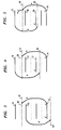
- FIGS. 3-5 demonstrate the problem.
- the signal s is sent at level 11, the echo brings the signal up to level 12, which is close to threshold 23 between levels 13 and 14.
- quantizer 10 within the central office chooses level 13, the signal e' is subtracted to yield level 15, and quantizer 20 develops signal s', which is at level 11 of signal s. In other words, no error is introduced.
- the small noise level happens to be positive and it moves the signal at the input of quantizer 10 to above threshold 23. The result is that quantizer 10 outputs level 14, the echo estimate is subtracted to reach level 16; but now quantizer 20 yields level 17 rather than level 11. That, of course, is a one-level error.
- the levels are not uniform (which indeed is the case in the ⁇ -law codec), and that leads to the possibility of a two-level error.
- the echo signal moves the input signal of quantizer 10 to level 18.
- the noise pushes the signal to above the threshold between level 19 and 21, so quantizer 10 develops level 21.
- quantizer 10 develops level 21.
- Subtracting the estimate signal e' yields level 22, and quantizer 20 develops the signal of level 24. That is two levels above level 11. It can be shown that the probability of an error of the type shown in FIG. 4 is substantially greater than an error of the type shown in FIG. 5.
- the quantized levels of signal s correspond to a set of symbols that are created by selector 52.
- the symbols of s and r can be viewed as a constellation of symbols along the x axis.
- the most prevalent error is an error that shifts a symbol to one of its neighbors in the constellation.
- the next most likely error is one that skips over a symbol in the constellation. If the set of quantized levels, s, is denoted in order (i.e., the first symbol is 00000, the next is 00001, the following one is 00010, etc.), then the most prevalent error is an error in the least significant bit of the symbol.
- the next most prevalent is in the next to the least significant bit of the symbol. It follows that whatever error correcting codes are incorporated into signal s, at least these two types of errors should be correctable.
- the number of useful levels in a ⁇ -Law codec is dependent on the level of noise immunity that is desired.
- fractional bit rate transmission results when a number of symbols L is developed from a number of input bits B, and the ratio of B/L is a mixed fraction.
- the mapping of bits into symbols also insures (through careful design of the mapping, as disclosed below) that those symbols which correspond to codec levels which we do not wish to use do not appear at the output of the mapper.
- the conventional means for implementing the mapping is through a look-up table memory; i.e. a ROM.
- the content of the memory used for performing the actual mapping can be prepared by using the modulus conversion approach mentioned above.
- the mapping installed in the ROM is computed only once.
- the data in the mapping memory can be arranged to improve a selected criterion, such as arranging for different probabilities of the symbols in order to reduce overall average power. This is demonstrated below.
- the overall signal constellation (of q ⁇ 2 u symbols, u being the number of unmapped bits) can be viewed as being divided into q subsets, denoted by S 1 , S 2 , ..., S q . If the probability of a symbol from the subset S i is pr i and P i is the average power of the symbols in this subset then, the overall average power is given by
- mapping 9 bits per 4 symbols This corresponds to 2.25 bits per symbol, as described in the penultimate row in Table I. and.
- the sequence (1 2 , ⁇ 2, ⁇ 3) for example, contains two symbols from subset S 1 , one symbol is either from S 2 or from S -2 , and one symbol is either from S 3 or from S -3 .
- the number of sequences of this type is
- Table II The sequence # of combinations (1 4 ) 1 (1 3 , ⁇ 2) 8 (1 2 , ⁇ 2 2 ) 24 (1, ⁇ 2 3 ) 32 ( ⁇ 2 4 ) 16 (1 3 , ⁇ 3) 8 (1 2 , ⁇ 2, ⁇ 3) 48 (1, ⁇ 2 2 , ⁇ 3) 96 ( ⁇ 2 3 , ⁇ 3) 64 ( ⁇ 3 2 ) 24 ( ⁇ 2 2 , ⁇ 3 2 ) 96 ( ⁇ 2, ⁇ 3 3 ) 64
- the value of Pa would be -12.22 dbm, which means that a gain of approximately 1dbm can be obtained merely by a wise selection of the mapped symbols.
- Table III The sequence # of combinations (1 4 ) 1 (1 3 , ⁇ 2) 8 (1 2 , ⁇ 2 2 ) 24 (1, ⁇ 2 3 ) 32 ( ⁇ 2 4 ) 16 (1 3 , ⁇ 3) 8 (1 2 , ⁇ 2, ⁇ 3) 48 (1, ⁇ 2 2 , ⁇ 3) 96 ( ⁇ 2 3 , ⁇ 3) 64 (1 2 , ⁇ 3 2 ) 24 ( ⁇ 2 2 , ⁇ 3 2 ) 96 ( ⁇ 2, ⁇ 3 3 ) 64 ( ⁇ 3 4 ) 16 (1, ⁇ 2, ⁇ 3 2 ) 96 (1, ⁇ 3 3 ) 32
- the minimum distance between the symbols from S 1 is smaller than that of the symbols from S 3 and, therefore, different error protection may be advantageous for a symbol taken from different subsets. For instance, probably no error protection is required for symbols from S 3 and S -3 , small correction capability may be desired for symbols from S 2 and S -2 , and large correction capability is desired for symbols from S 1 .
- the selection presented in Table IV ensures that at least one of the symbol in the sequence is either from S 3 or from S -3 and that chocie increases the data through-put since no error correcting redundancy need to be included.
- Table IV The sequence # of combinations (1 3 , 3) 8 (1 2 , ⁇ 2, ⁇ 3) 48 (1, ⁇ 2 2 , ⁇ 3) 96 ( ⁇ 2 3 , ⁇ 3) 64 (1 2 , ⁇ 3 2 ) 24 ( ⁇ 2 2 , ⁇ 3 2 ) 96 (1, ⁇ 2, ⁇ 3 2 ) 96 (1, ⁇ 3 3 ) 32 ( ⁇ 2, ⁇ 3 3 ) 48
- the mapping schema disclosed herein is based on the notion of selecting a particular mapping that advances a particular cirterion. If it is desired to minimize the average power (a kind of shaping code) , the probability of subsets with low power symbols should be increased. In the case of a non-equally spaced constellation, increasing the data rate can be achieved by reducing the number of symbols for which error protection is required. Similar to error correction coding, where an increase in the coding gain can be achieved by increasing the redundancy, the effective redundancy in the mapping can be increased. Using the same size of signal constellation with reduced number of bits per symbol can be interpreted as increasing the redundancy. By increasing the redundancy the probability of subsets that comply with the desired criterion can also be increased.
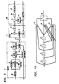
- FIG. 6 shows one example of such an arrangement where every one of the bits that is not mapped is applied to a coder
- FIG. 7 shows an example where only some of the bits that do not participate in the fractional bit rate mapping are encoded (and the other ones are not)
- FIG. 8 presents an example where the encoding is multi-level.
- FIG. 9 presents an arrangement according to the principles disclosed herein where it may be noted that elements 30, 31, 32, and 33 replace mapper 51 of FIG. 1.
- Equalizer 53 can follow the principles taught in U.S. patent application filed for Ayangolu et al, entitled “High Speed Quantization-Level-Sampling Modem with Equalization Arrangement", dated January 3, 1994, and bearing the serial number 08/176742.
- a rate that is lower than 8 bits per symbol is the result.
- a rate of 6.73333 is good for certain applications, and that rate corresponds to a transmission of 202 information bits with every 30 symbols. That is with every 202 information bits that flow through buffer 30, there are 30 symbols that are created by blocks 30-33.
- buffer 30 delivers 11 bits to fractional bit rate mapper 33, in response to which mapper 33 delivers 6 bits with every symbol period. Effectively, mapper 33 creates a bit every two symbols.
- the output of this mapping is capable of supporting an alphabet of 2 12 , but since the input is restricted to 2 11 combinations, there are some members of the alphabet that are never applied to level selector 52.
- the 6 bits of mapper 33 form the most significant bits of the symbols applied to the level selector.
- buffer 30 delivers 27 bits to encoder 32.
- Encoder 32 correspondingly, delivers a single bit to level selector 52 with every symbol period. Effectively, encoder 32 creates a bit every 10 symbol periods.
- the output of encoder 32 forms the next to least significant bit of the symbols applied to the level selector.
- buffer 30 delivers 10 bits to encoder 31, and encoder 31 delivers a single bit to level selector 52 with every symbol period.
- encoder 31 creates a 2 bits every 3 symbol periods.
- the output of encoder 31 forms the least significant bit of the symbols applied to the level selector.
- bits of the 202 bits are employed by encoders 31, 32 or 33 is not important, so any convenient routing algorithm will do, as long as that algorithm is known, so that the received symbols can be decomposed eventually into the proper sequence of bits.
- mapper 33 may be a ROM with the 11 bit input being merely an address that is applied to the ROM.
- the ROM has 12 outputs which are divided into two groups of 6 bits each, and the groups are alternately directed to the output of mapper 33 with each symbol period.
- Mapper 32 for example, may be a simple parity code generator which for every 9 bits adds a parity bit.
- Mappers 31 and/or 32 may be block encoders or convolutional encoders. An illustrative convolutional encoder for mapper 31 is shown in FIG. 10. The coder of FIG.
- 10 includes 4 delay elements, modulo 2 adders 35, 36, and 37 and commutating switch 38. With every set of three symbols interval, a bit is inserted into the first delay element 34 of the FIG. 10 encoder (with data shifting through the succeeding delay elements). Switch 38 accesses a different adder with each symbol interval and commutates among the three adders.
- FIG. 11 Such an arrangement is depicted in FIG. 11, where the multi-level encoder is the same as in FIG. 8, and the only change is in the number of bits that are produced by Fractional Bit Rate (FBR) mapper 39.
- FBR Fractional Bit Rate
- modem 5 of FIG. 9 includes a means for incorporating error protection for the two least significant bits of the symbols applied to level selector 52 and, thence, to quantizer 10 is not the end of the journey, of course. Means must be provided in element 200 to make use of the error correcting codes and to thereby correct the errors that might otherwise appear at the output. That task is assigned to decoder 60.
- the conventional approach for correcting such errors is through "soft decoding", where the actual level that is obtained after subtracting the echo estimate, e', is evaluated vis-à-vis the two possible quantized values that the signal might assume. Describing the process very generally, a "cost/benefit" metric is assigned to the two choices and the "metric" is accumulated over the entire sequence of the 30 symbols.
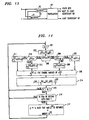
- FIG. 12 presents a flow diagram of the decoding algorithm performed in block 200 of FIG. 9, as it relates to the least significant bit. It describes the decoding of a block code where the block length is N.
- a Viterbi decoder can be used (see the aforementioned Gitlin reference), with the same "cost/benefit" metric as described below.
- the flow chart of FIG. 12 incorporates the action of elements 13 and 20, as well as the decoding of block 60. In other words, the FIG. 12 flow chart corresponds to an embodiment of block 200 via a stored program controlled processor that carries out the processing of FIG. 12.
- an index k which designates a member in a block of signals, is set to 1.
- Control passes to element 102, where signal t (the output of subtractor 13 in FIG. 9) is evaluated.
- Element 103 in FIG. 12 quantizes signal t in accordance with the reduced alphabet of the ⁇ -law encoder to obtain an intermediate signal, z ( k ) A , which corresponds to the output of block 20 in FIG. 9.
- the signal z ( k ) A is recognized to be associated with a label of the signal x ( k ) , which is the signal applied to block 60.
- the quantization performed by the Z operator of element 103 chooses the nearest of the two neighbors on either side of t ( k ) .
- the two neighbors are identified here by , z ( k ) A and z ( k ) B , where the neighbor that is closest to t ( k ) is chosen by the quantization process to be labeled Z ( k ) A .
- Decision element 105 determines whether the quantization of signal t ( k ) chose a lower level neighbor or a higher level neighbor.
- decision element 106 determines whether the corresponding label, x ( k ) A is equal to M-1, where M is the number of labels in the block 60 modem (M-1 is the last label in the set of labels and corresponds to the biggest binary number).
- element 107 sets the other neighbor, x ( k ) B , to M-2, and control passes to element 108.
- element 109 sets x ( k ) B to x ( k ) A +1 and, again, control passes to element 108.
- element 108 determines the z ( k ) B level that corresponds to x ( k ) B .
- Element 114 evaluates distances from thresholds, which relate to the "cost/benefit" metric, and control passes to element 115.
- the "metric" over the entire block associated with selecting, x ( k ) A or x ( k ) B is evaluated in the loop that follows element 115.
- Element 115 sets index i to zero and element 116 compares the value of i to the least significant bit of x ( k ) A , x ( k ) A 0 . When they are equal, the metric is determined in block 117.
- ⁇ 1 k ⁇ k 2 - x A k - t k
- ⁇ 2 k ⁇ k 2 - x B k - t k
- ⁇ is the distance between the thresholds that surround r ( k ) .
- Control passes to element 121, with ⁇ ( k ) 1 and ⁇ ( k ) 0 determined and the index k incremented.
- a sub-optimal decoding can take place, with the "cost/benefit" metric defined by ⁇ ( k ) 1 , ⁇ ( k ) 2 being equal to ⁇ 2 2 when ⁇ 2 1 ⁇ 0 and ⁇ 2 2 ⁇ 0 ; being equal to 0 when ⁇ 1 ⁇ 0 and ⁇ 2 ⁇ 0 ; and being equal to ⁇ 2 2 - ⁇ 2 1 when ⁇ 1 ⁇ 0 and ⁇ 2 ⁇ 0.
- element 121 increments index k and passes control to decision element 122.
- element 122 passes control back to element 102.
- control passes to element 123 where index i is set to zero and the process of determining the best suited codeword commences.
- Element 124 evaluates the accumulated metrics for the i th codeword, E i , element 125 increments index i, and element 126 determines whether a metric of a next codeword should be evaluated.
- the index i is not greater than the number of codewords in E, control returns to element 124 (where E is the error correcting code used for the least significant bit). Otherwise, element 127 identifies the index i for which the maximum benefit is obtained, and the value of this index is memorialized by assigning it to index f. Control then passes to element 128, where index, k, is set to one.
- decision element 113 compares the least significant bit of the k th component in the code corresponding to index f, E ( k ) f to x ( k ) A 0 and, if they are equal, then the final estimate of the sent label, x ⁇ (k) is set equal to x ( k ) A , and the final estimate of the sent symbol, ⁇ (k) is set to z ( k ) A . This is accomplished in element 130.
- element 131 When decision element 113 obtains a false answer, then pursuant to element 131, the final estimate of the sent label, x ⁇ ( k ) , is set equal to x ( k ) B , and the final estimate of the sent symbol, ⁇ ( k ) , is set to z ( k ) B . Thereafter, element 131 increments k by one and, if k is not greater than N, then according to decision element 132, control returns to decision element 113. Otherwise, element 133 sets k equal to one and control returns to element 102 to start decoding another block.
- the result of the FIG. 12 process is a selection of a symbol which satisfies the criteria imposed by encoder 31 and which probably is the symbol that was sent. More specifically, it is a symbol that is part of a valid codeword and it has the correct least significant bit. What remains to be determined is whether the other bits are also the correct bits, and in particular, whether the next-to-least-significant bit is correct.
- decoder 61 corresponds to the flow chart of FIG. 12 and it determines the least significant bit of the symbol while it determines a tentative symbol, ⁇ . That symbol is applied to decoder 62 which identifies a valid level that comports with the requirements of encoder 32 and, by doing so, identifies the next-to-least-significant bit of the final symbol, s', as well as the remaining bits. Since the next-to-least-significant bit of the symbol was derived through simple parity check encoding, the process of correcting that bit is somewhat simpler than the process shown in FIG. 12. That process is presented in FIG. 14.
- decoders 61 and 62 corresponds to the least significant bits that were applied to the error correction encoding of elements 31 and 32, and to the bits at the output of mapper 33.
- a simple table look-up translation may be employed, and that is accomplished via translator 63.
- element 201 sets index k to 1, and element 202 determines the level t ( k ) , which is r ( k ) - e ( k ) .
- element 206, 207 and 209 look at x ⁇ ( k ) , which is the label associated with ⁇ ( k ) , and select a neighboring label, x ( k ) 2 Control then passes to element 208.
- elements 210, 211 and 213 also select label, x ( k ) 2 and pass control to element 208.
- Element 208 associates symbol S ( k ) 2 with level x ( k ) 2 .
- element 215 determines whether k is less than N-1, where N is the length of the block (the length of blocks in encoding the least significant bit and the next-to-least significant bit do not need to be the same), and in such a circumstance, control returns to element 201 to determine the metric associated with another member of the block. Otherwise, control passes to element 216 where a determination is made regarding the parity of the signal; i.e., the parity of the second bit in the label of the symbol.
Landscapes
- Engineering & Computer Science (AREA)
- Physics & Mathematics (AREA)
- Computer Networks & Wireless Communication (AREA)
- Signal Processing (AREA)
- Theoretical Computer Science (AREA)
- Spectroscopy & Molecular Physics (AREA)
- Power Engineering (AREA)
- Probability & Statistics with Applications (AREA)
- Digital Transmission Methods That Use Modulated Carrier Waves (AREA)
- Error Detection And Correction (AREA)
- Compression, Expansion, Code Conversion, And Decoders (AREA)
- Detection And Correction Of Errors (AREA)
Applications Claiming Priority (2)
| Application Number | Priority Date | Filing Date | Title |
|---|---|---|---|
| US384514 | 1995-02-01 | ||
| US08/384,514 US5659579A (en) | 1995-02-01 | 1995-02-01 | Multilevel coding for fractional bits |
Publications (2)
| Publication Number | Publication Date |
|---|---|
| EP0725487A2 true EP0725487A2 (de) | 1996-08-07 |
| EP0725487A3 EP0725487A3 (de) | 1998-05-13 |
Family
ID=23517626
Family Applications (1)
| Application Number | Title | Priority Date | Filing Date |
|---|---|---|---|
| EP96300482A Withdrawn EP0725487A3 (de) | 1995-02-01 | 1996-01-24 | Mehrpegelkodierung für fraktionelle Bits |
Country Status (7)
| Country | Link |
|---|---|
| US (1) | US5659579A (de) |
| EP (1) | EP0725487A3 (de) |
| JP (1) | JP3489705B2 (de) |
| KR (1) | KR100383029B1 (de) |
| CN (1) | CN1108664C (de) |
| CA (1) | CA2167746C (de) |
| TW (1) | TW285792B (de) |
Cited By (13)
| Publication number | Priority date | Publication date | Assignee | Title |
|---|---|---|---|---|
| WO1998039883A1 (en) * | 1997-03-03 | 1998-09-11 | 3Com Corporation | Signalling method using multiple modulus conversion and shell mapping |
| WO1998025384A3 (en) * | 1996-12-04 | 1998-09-17 | Fernway Ltd | A method for trellis coding a logarithmic distribution of constellation points |
| EP0871311A3 (de) * | 1997-04-08 | 1999-06-16 | Frederic J. Hirzel | Verfahren zur veränderbaren Spektralformung für PCM-Modems |
| EP0876030A3 (de) * | 1997-04-29 | 1999-06-16 | Lucent Technologies Inc. | System und Verfahren zur dynamischen Optimierung einer Symboltabelle und Modem,d er diese verwendet |
| EP0852438A3 (de) * | 1996-12-04 | 1999-06-23 | Rockwell Science Center, Inc. | Trellisformung für Mehrpegelübertragung, wobei die Pegel zur Netzwerkquantisierung angepasst sind |
| WO1999038299A1 (en) * | 1998-01-26 | 1999-07-29 | Conexant Systems, Inc. | Multiple modulus conversion techniques for pcm modem |
| US5995548A (en) * | 1996-11-15 | 1999-11-30 | 3Com Corporation | Signaling method using multiple modulus shell mapping |
| US6084915A (en) * | 1997-03-03 | 2000-07-04 | 3Com Corporation | Signaling method having mixed-base shell map indices |
| US6084883A (en) * | 1997-07-07 | 2000-07-04 | 3Com Corporation | Efficient data transmission over digital telephone networks using multiple modulus conversion |
| EP0919087A4 (de) * | 1997-01-17 | 2001-08-16 | Motorola Inc | System, einrichtung und verfahren zur vermittlung nach einem zusammengesetzen kode |
| EP0880838A4 (de) * | 1996-11-14 | 2001-08-29 | Motorola Inc | Verfahren zur übertragung nach einer trelliskode, die aus einer festen menge basisbandsignalpunkte gewählt wird |
| WO2002060146A1 (en) * | 2001-01-26 | 2002-08-01 | Nokia Corporation | Method of implementing modulation and modulator |
| US6643270B1 (en) | 1998-03-03 | 2003-11-04 | Vocal Technologies, Ltd | Method of compensating for systemic impairments in a telecommunications network |
Families Citing this family (26)
| Publication number | Priority date | Publication date | Assignee | Title |
|---|---|---|---|---|
| US6889356B1 (en) * | 1994-11-23 | 2005-05-03 | Cingular Wireless Ii, Llc | Cyclic trellis coded modulation |
| FR2751811B1 (fr) * | 1996-07-24 | 1998-10-09 | Matra Communication | Procede de demodulation numerique |
| US5818879A (en) * | 1996-10-15 | 1998-10-06 | Motorola Inc. | Device, system and method for spectrally shaping transmitted data signals |
| DE19782004T1 (de) * | 1996-09-24 | 1999-09-09 | Motorola Inc | Verfahren zur Bildung eines tatsächlichen Alphabets von Symbolen, das in einem Kommunikationssystem zu verwenden ist, in einem Kommunikationssystem verwendbarer Adapter, und Kommunikationssystem |
| EP0927481A4 (de) * | 1996-09-25 | 2003-04-23 | Motorola Inc | Einrichtung, system und verfahren zur formung des spektrums eines übertragenen datensignals |
| US5926505A (en) * | 1996-10-16 | 1999-07-20 | Cirrus Logic, Inc. | Device, system, and method for modem communication utilizing two-step mapping |
| US6198776B1 (en) | 1996-11-13 | 2001-03-06 | Motorola Inc. | Device and method for precoding data signals for PCM transmission |
| EP0851621B1 (de) * | 1996-12-23 | 2004-06-09 | Canon Kabushiki Kaisha | Kodierte Modulation für Konstellationen, welche weniger Bits pro Symbol haben, als vom Kodierungsschema verlangt wird |
| US5970098A (en) * | 1997-05-02 | 1999-10-19 | Globespan Technologies, Inc. | Multilevel encoder |
| JPH10336147A (ja) * | 1997-06-03 | 1998-12-18 | Oki Electric Ind Co Ltd | Cdma送受信装置および送信レート可変方法 |
| EP1038379B1 (de) * | 1997-12-29 | 2008-07-30 | Motorola, Inc. | Methode und apparat zum auswählen eines konstellationspunktes für jede gruppe von datenbits, welche durch ein analoges pcm-modem übertragen werden sollen |
| US20020167949A1 (en) * | 1998-02-26 | 2002-11-14 | Gordon Bremer | Apparatus and method for asynchronous transfer mode (ATM) adaptive time domain duplex (ATDD) communication |
| US6950444B1 (en) * | 1999-08-24 | 2005-09-27 | Paradyne Corporation | System and method for a robust preamble and transmission delimiting in a switched-carrier transceiver |
| US6163570A (en) | 1998-05-11 | 2000-12-19 | Conexant Systems, Inc. | Methods and apparatus for verifying transmit power levels in a signal point limited transmission system |
| US7254167B2 (en) | 1998-10-30 | 2007-08-07 | Broadcom Corporation | Constellation-multiplexed transmitter and receiver |
| US6731692B1 (en) * | 2000-03-23 | 2004-05-04 | Agere Systems Inc. | Symbol encoding and decoding architecture for trellis-coded modulation in gigabit ethernet |
| JP3753678B2 (ja) * | 2002-06-28 | 2006-03-08 | Necマイクロシステム株式会社 | 多値画像符号化・復号化装置 |
| US20040096009A1 (en) * | 2002-11-14 | 2004-05-20 | Unb Technologies, Inc. | Communications methods including narrow band modulation |
| US20040096010A1 (en) * | 2002-11-14 | 2004-05-20 | Unb Technologies Inc. | Communications system including a narrow band modulator |
| US7071849B2 (en) * | 2004-04-04 | 2006-07-04 | Guobiao Zhang | Fractional-Bit Systems |
| EP1774655A1 (de) * | 2004-07-27 | 2007-04-18 | Koninklijke Philips Electronics N.V. | Codierung von datenwörtern unter verwendung von drei oder mehr signalebenen |
| US7167109B2 (en) * | 2005-03-31 | 2007-01-23 | Chenming Hu | Hybrid fractional-bit systems |
| JP4900192B2 (ja) * | 2007-10-22 | 2012-03-21 | 沖電気工業株式会社 | 符号分割多重送受信装置及び符号分割多重送受信方法 |
| US9805442B2 (en) * | 2012-10-03 | 2017-10-31 | Avago Technologies General Ip (Singapore) Pte. Ltd. | Fine-grained bit-rate control |
| KR102159242B1 (ko) | 2014-05-21 | 2020-09-24 | 삼성전자주식회사 | 송신 장치 및 그의 신호 처리 방법 |
| US10727951B2 (en) * | 2016-07-20 | 2020-07-28 | Nokia Of America Corporation | Low-complexity constellation shaping |
Family Cites Families (10)
| Publication number | Priority date | Publication date | Assignee | Title |
|---|---|---|---|---|
| US4622670A (en) * | 1984-12-10 | 1986-11-11 | At&T Bell Laboratories | Error-correction coding for multilevel transmission system |
| DE3805169A1 (de) * | 1988-02-19 | 1989-08-31 | Inst Rundfunktechnik Gmbh | Verfahren zum uebertragen eines digital-codierten tonsignals |
| US5248641A (en) * | 1990-09-17 | 1993-09-28 | Southern Clay Products, Inc. | Process for producing bentonite clays exhibiting enhanced solution viscosity properties |
| US5185763A (en) * | 1991-04-09 | 1993-02-09 | Racal-Datacom, Inc. | Data bit to constellation symbol mapper |
| US5119403A (en) * | 1991-04-09 | 1992-06-02 | Racal Data Communications Inc. | Superframes |
| US5305352A (en) * | 1991-10-31 | 1994-04-19 | At&T Bell Laboratories | Coded modulation with unequal error protection |
| US5329551A (en) * | 1992-04-16 | 1994-07-12 | At&T Bell Laboratories | Overlapped multilevel codes |
| JPH06125533A (ja) * | 1992-10-13 | 1994-05-06 | Sony Corp | エラー訂正コード付加装置及びエラー訂正装置 |
| WO1994011955A1 (en) | 1992-11-06 | 1994-05-26 | Pericle Communications Company | Adaptive data rate modem |
| US5486825A (en) * | 1994-04-20 | 1996-01-23 | General Datacomm, Inc. | Convolutional encoders for modems which implement the "Cole code" |
-
1995
- 1995-02-01 US US08/384,514 patent/US5659579A/en not_active Expired - Lifetime
-
1996
- 1996-01-22 CA CA002167746A patent/CA2167746C/en not_active Expired - Fee Related
- 1996-01-24 TW TW085100839A patent/TW285792B/zh not_active IP Right Cessation
- 1996-01-24 EP EP96300482A patent/EP0725487A3/de not_active Withdrawn
- 1996-01-30 KR KR1019960002051A patent/KR100383029B1/ko not_active Expired - Fee Related
- 1996-01-31 CN CN96101337A patent/CN1108664C/zh not_active Expired - Fee Related
- 1996-02-01 JP JP01651896A patent/JP3489705B2/ja not_active Expired - Fee Related
Cited By (16)
| Publication number | Priority date | Publication date | Assignee | Title |
|---|---|---|---|---|
| EP0880838A4 (de) * | 1996-11-14 | 2001-08-29 | Motorola Inc | Verfahren zur übertragung nach einer trelliskode, die aus einer festen menge basisbandsignalpunkte gewählt wird |
| US5995548A (en) * | 1996-11-15 | 1999-11-30 | 3Com Corporation | Signaling method using multiple modulus shell mapping |
| WO1998025384A3 (en) * | 1996-12-04 | 1998-09-17 | Fernway Ltd | A method for trellis coding a logarithmic distribution of constellation points |
| EP0852438A3 (de) * | 1996-12-04 | 1999-06-23 | Rockwell Science Center, Inc. | Trellisformung für Mehrpegelübertragung, wobei die Pegel zur Netzwerkquantisierung angepasst sind |
| EP0919087A4 (de) * | 1997-01-17 | 2001-08-16 | Motorola Inc | System, einrichtung und verfahren zur vermittlung nach einem zusammengesetzen kode |
| US6084915A (en) * | 1997-03-03 | 2000-07-04 | 3Com Corporation | Signaling method having mixed-base shell map indices |
| WO1998039883A1 (en) * | 1997-03-03 | 1998-09-11 | 3Com Corporation | Signalling method using multiple modulus conversion and shell mapping |
| EP0871311A3 (de) * | 1997-04-08 | 1999-06-16 | Frederic J. Hirzel | Verfahren zur veränderbaren Spektralformung für PCM-Modems |
| EP0876030A3 (de) * | 1997-04-29 | 1999-06-16 | Lucent Technologies Inc. | System und Verfahren zur dynamischen Optimierung einer Symboltabelle und Modem,d er diese verwendet |
| US6084883A (en) * | 1997-07-07 | 2000-07-04 | 3Com Corporation | Efficient data transmission over digital telephone networks using multiple modulus conversion |
| WO1999038299A1 (en) * | 1998-01-26 | 1999-07-29 | Conexant Systems, Inc. | Multiple modulus conversion techniques for pcm modem |
| US6034991A (en) * | 1998-01-26 | 2000-03-07 | Conexant Systems, Inc. | Method and apparatus for implementing enhanced multiple modulus conversion techniques in a signal point mapping context |
| US6438158B1 (en) | 1998-01-26 | 2002-08-20 | Conexant Systems, Inc. | Method and apparatus for implementing enhanced multiple modulus conversion techniques in a signal point mapping context |
| US6643270B1 (en) | 1998-03-03 | 2003-11-04 | Vocal Technologies, Ltd | Method of compensating for systemic impairments in a telecommunications network |
| WO2002060146A1 (en) * | 2001-01-26 | 2002-08-01 | Nokia Corporation | Method of implementing modulation and modulator |
| US7274753B2 (en) | 2001-01-26 | 2007-09-25 | Nokia Corporation | Method of implementing modulation and modulator |
Also Published As
| Publication number | Publication date |
|---|---|
| CA2167746C (en) | 1999-12-07 |
| CA2167746A1 (en) | 1996-08-02 |
| JPH08274822A (ja) | 1996-10-18 |
| KR100383029B1 (ko) | 2003-08-14 |
| CN1108664C (zh) | 2003-05-14 |
| US5659579A (en) | 1997-08-19 |
| CN1135685A (zh) | 1996-11-13 |
| KR960032906A (ko) | 1996-09-17 |
| JP3489705B2 (ja) | 2004-01-26 |
| TW285792B (de) | 1996-09-11 |
| EP0725487A3 (de) | 1998-05-13 |
Similar Documents
| Publication | Publication Date | Title |
|---|---|---|
| US5659579A (en) | Multilevel coding for fractional bits | |
| US5710790A (en) | Communication arrangement with improved echo and noise suppression in a channel containing quantization | |
| JP2645432B2 (ja) | 通信システム用受信機、データ回復方法、送信機、及び通信システム | |
| US5995558A (en) | Rob bit compensation system and method associated with a receiver or codec | |
| US6084883A (en) | Efficient data transmission over digital telephone networks using multiple modulus conversion | |
| US4605826A (en) | Echo canceler with cascaded filter structure | |
| JP4160097B2 (ja) | アナログ加入者接続のための高速通信システム | |
| US6463103B1 (en) | Frame-based sign inversion method and system for spectral shaping for pulse-coded-modulation modems | |
| US5251236A (en) | Fractional rate modem with trellis | |
| US6823002B1 (en) | Linear block interleaver for discrete multi-tone modulation | |
| WO1999066684A1 (en) | Device, system and method for modem communication utilizing dc or near-dc signal suppression | |
| US5588028A (en) | Simplified trellis decoder | |
| US6301296B1 (en) | Digital impairment learning sequence | |
| EP0880838B1 (de) | Verfahren zur übertragung nach einer trelliskode, die aus einer festen menge basisbandsignalpunkte gewählt wird | |
| KR20010033691A (ko) | 최적화 전송 컨스텔레이션을 이용한 pcm 업스트림 전송시스템, 장치 및 방법 | |
| US6532267B1 (en) | Variable rate constellation precoding | |
| CN1193424A (zh) | 自适应增益控制器 | |
| WO2000044124A1 (en) | Method and apparatus for combining a trellis coding scheme with a pre-coding scheme for data signals | |
| Coward et al. | Quantizer optimization in hybrid digital-analog transmission of analog source signals | |
| EP1363431B1 (de) | Konstellationsentwurf für PCM -Aufwärtsmodulation | |
| KR100821403B1 (ko) | 업스트림 v.92-인코드된 신호의 디코딩 | |
| JP2000358113A (ja) | 電話ネットワーク劣化を検出し補償する方法 | |
| US6931072B2 (en) | Upstream data transmission | |
| RU2801163C1 (ru) | Устройство для многоуровневого кодирования | |
| US20040174936A1 (en) | Receiver codec super set constellation generator |
Legal Events
| Date | Code | Title | Description |
|---|---|---|---|
| PUAI | Public reference made under article 153(3) epc to a published international application that has entered the european phase |
Free format text: ORIGINAL CODE: 0009012 |
|
| AK | Designated contracting states |
Kind code of ref document: A2 Designated state(s): DE FR GB |
|
| PUAL | Search report despatched |
Free format text: ORIGINAL CODE: 0009013 |
|
| AK | Designated contracting states |
Kind code of ref document: A3 Designated state(s): DE FR GB |
|
| 17P | Request for examination filed |
Effective date: 19981029 |
|
| STAA | Information on the status of an ep patent application or granted ep patent |
Free format text: STATUS: THE APPLICATION IS DEEMED TO BE WITHDRAWN |
|
| 18D | Application deemed to be withdrawn |
Effective date: 20020801 |