EP0725527A1 - Sprachkonferenz-Echokompensatorsystem - Google Patents
Sprachkonferenz-Echokompensatorsystem Download PDFInfo
- Publication number
- EP0725527A1 EP0725527A1 EP95117690A EP95117690A EP0725527A1 EP 0725527 A1 EP0725527 A1 EP 0725527A1 EP 95117690 A EP95117690 A EP 95117690A EP 95117690 A EP95117690 A EP 95117690A EP 0725527 A1 EP0725527 A1 EP 0725527A1
- Authority
- EP
- European Patent Office
- Prior art keywords
- echo
- signal
- output
- circuit
- subtracting
- Prior art date
- Legal status (The legal status is an assumption and is not a legal conclusion. Google has not performed a legal analysis and makes no representation as to the accuracy of the status listed.)
- Withdrawn
Links
Images




Classifications
-
- H—ELECTRICITY
- H04—ELECTRIC COMMUNICATION TECHNIQUE
- H04M—TELEPHONIC COMMUNICATION
- H04M9/00—Arrangements for interconnection not involving centralised switching
- H04M9/08—Two-way loud-speaking telephone systems with means for conditioning the signal, e.g. for suppressing echoes for one or both directions of traffic
- H04M9/082—Two-way loud-speaking telephone systems with means for conditioning the signal, e.g. for suppressing echoes for one or both directions of traffic using echo cancellers
Definitions
- the present invention relates to an echo cancelling system and, more particularly,to an echo cancelling system suitable for a two-wire voice conference.
- An echo canceller has customarily been used in order to suppress echoes to occur at a hybrid circuit which intervenes between a two-wire subscriber line and a four-wire channel constituting a transmission path.
- advances in the multifunction configuration of a telephone have led to a voice conference apparatus and a TV telephone apparatus incorporating it.
- the problem with this kind of voice conference apparatus is that noise inside and outside of a conference room is input to a microphone together with voice, obstructing the conference.
- the echo canceller is used to cancel such noise.
- the conventional echo canceller for voice conferences estimates an echo of a direction opposite to an expected direction during the course of bidirectional conversation and at the end of a word, resulting in estimation errors.
- the echo canceller amplifies the echo rather than cancelling it, thereby bringing about howling.
- an object of the present invention to provide an echo cancelling system capable of cancelling echoes with accuracy.
- An echo cancelling system of the present invention has a first echo estimator for estimating a channel echo component contained in a received signal due to a hybrid circuit, and capable of being activated by an external control signal.
- a second echo estimator estimates a room echo component contained in a signal to be sent and fed to the hybrid circuit, and capable of being activated by an external control signal.
- a first subtracter subtracts the channel echo component estimated by the first echo estimator from the received signal.
- a second subtracter subtracts the room echo component estimated by the second echo estimator from the signal to be sent.
- a first echo suppressor suppresses a residual echo of an output signal of the first subtracter by the received signal output from the first subtracter and the signal to be sent and output from the second subtracter, and outputs the resulting suppressed state.
- a second echo suppressor suppresses a residual echo of an output signal of the second subtracter by the signal to be sent and output from the second subtracter and the received signal output from the first subtracter, and outputs the resulting suppressed state.
- a first estimation controller determines a speech direction and an amount of suppression by referencing the received signal from the hybrid circuit, the output signal of the first subtracter, the signal to be sent and applied to the hybrid circuit, and the suppressed state output from the first echo suppressor, and generates the external control signal for the first echo estimator.
- a second estimation controller determines a speech direction and an amount of suppression by referencing the signal to be transmitted and fed from the microphone, the output signal of the second subtracter, the signal to be sent and fed to the speaker, and the suppressed state output from the second echo suppressor, and generates the external control signal for the second echo estimator.
- an echo estimator 4 estimates an echo signal, i.e., a part of the output signal of a speaker 1 which turns round to a microphone 2.
- a subtracter 3 subtracts the estimated echo signal from an input signal from the microphone 2, thereby cancelling an echo.
- Another echo estimator 17 estimates an echo signal attributable to the turn-round of the output signal of a hybrid transformer 19, which is to be transmitted, to a received input signal.
- a subtracter 18 subtracts the echo signal estimated by the estimator 17 from a received input signal.
- a residual echo suppressor 5 compares the output signal of the speaker 1 and that of the subtracter 3 as to their levels in order to determine a conversation condition, i.e., a direction in which conversation is held, thereby suppressing a residual echo.
- Another residual echo suppressor 16 compares the level of the signal to be output to a channel and that of the output of the subtracter 18 so as to determine a conversation condition, thereby suppressing a residual echo.
- mean circuits 7 and 8 respectively produce the level of the speaker output signal and that of the microphone output signal and deliver them to the estimation controller 9.
- the estimation controller 9 compares the levels of the two input signals. If the microphone input signal is lower in level than the speaker output signal, the controller 9 causes the echo estimator 4 to perform estimation.
- mean circuits 13 and 14 are connected to an estimation controller 11 and respectively feed to the controller 11 the level of the hybrid transformer output and that of the hybrid transformer input. If the transformer input signal is lower in level than the transformer output signal, the controller 11 causes the echo estimator 17 to perform estimation.
- the above echo cancelling system is apt to estimate echoes of the direction opposite to the expected direction during the course of bidirectional conversation or at the end of a word, resulting in estimation errors, as stated earlier.
- the system does not cancel echoes, but it amplifies them and brings about howling.
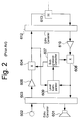
- Fig. 2 shows another convensional echo cancelling system.
- the system has an echo canceller 603 for cancelling an echo signal attributable to the turn-round of the output of a speaker 601 to a microphone 602.
- An echo canceller 612 cancels an echo signal attributable to the turn-round of an output of a hybrid transformer 613, which is to be transmitted, to a received input.
- An amplifier 606 amplifies the output of the echo canceller 603 in order to prevent a residual echo remaining at the acoustic side from returning to the channel side.
- An amplifier 610 adjusts the signal level to reach the speaker 601.
- a multiplier 604 also prevents a residual echo remaining at the acoustic side from returning to the channel side.
- a multiplier 608 prevents a residual echo remaining at the channel side from returning to the speaker 601.
- a level comparator 609 compares the levels of the suppressed outputs of the multipliers 604 and 608 in order to determine which of the talkers is speaking, i.e., a speech direction as referred to hereinafter.
- the speech direction is fed to a suppression controller 607. If, for example, the output level of the multiplier 604 is higher than that of the multiplier 608, the suppression controller 607 reduces the amount of suppression assigned to the multiplier 604 while increasing the amount of suppression assigned to the multiplier 608.
- the problem with the configuration shown in Fig. 2 is that when one of the echo cancellers 603 and 612 has not completed echo estimation, the level comparison described above fails to determine a speech direction with accuracy. For example, when the echo canceller 612 has not fully cancelled an echo, the microphone input signal is reflected by the transformer 613. As a result, an echo signal is amplified by the amplifier 610. When the amplification factor of the amplifier 610 is great, the level comparator 609 is likely to determine that the speaker output signal is higher in level than the microphone input signal.
- an echo cancelling system embodying the present invention will be described which constitutes an improvement over the conventional system shown in Fig. 1.
- the same or similar constituents as or to the constituents shown in Fig. 1 are designated by the same reference numerals.
- the embodiment executes echo estimation on three different conditions, i.e., that a reference signal (speaker output signal) level be present (condition 1), that an amount of echo cancellation matching echo estimation be guaranteed (condition 2), and that a residual echo be sufficiently suppressed (condition 3).
- an echo estimator 4 detects the level of a signal to be output via a speaker 1 and thereby estimates an echo attributable to the turn-round of the speaker output signal to a microphone 2.
- a subtracter 3 subtracts the output of the estimator 4, i.e., a false error signal from the echo signal, thereby cancelling the echo.
- a residual echo suppressor 5 suppresses a residual echo left after the echo cancellation, thereby eliminating the return of the echo.
- a mean circuit 8 produces a mean value of the speaker output signal.
- An estimation controller 9 monitors the output signal of the mean circuit 8 to see if the condition 1 is satisfied or not..
- mean circuits 7 and 6 respectively produce the mean value of the output signal of the microphone 2 and the mean value of the output signal of the subtracter 3, and deliver them to the estimation controller 9.
- the controller 9 compares the outputs of the mean circuits 6 and 7 so as to monitor the amount of echo cancellation. In addition, the controller 9 monitors the output of the residual echo suppressor 5 to see if the condition 3 is satisfied or not.
- An amplifier 10 adjusts the level of the microphone input signal to be transmitted.
- An amplifier 12 adjusts the level of a signal received over a channel and to be applied to the speaker 2.
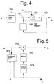
- Fig. 4 shows a specific configuration of each of the mean circuits 6, 7 and 8.
- the circuit has an absolute value circuit 106 for converting the input signal to an absolute value.
- a subtracter 101 produces a difference between the absolute value and the current mean value.
- a multiplier 102 multiplies the difference by a certain small value (c1).
- the resulting product is added to the current mean value by an adder 103.
- the output of the adder 103 is shifted by the shift register 105 and used as a current mean value for the next input signal.
- Fig. 5 shows a specific configuration of each of the residual echo suppressors 5 and 16.
- the echo suppressor detects a speech direction and suppresses the residual echo remaining after the echo cancellation.
- the suppressor 5 has a decision circuit 201 for comparing the level of the speaker output signal and that of the signal undergone echo cancellation. For example, when the speaker output signal is sufficiently higher in level than the signal produced by cancelling the echo of the microphone input signal (e.g. by 12 dB), the decision circuit 201 determines that suppression should be executed, and then changes the address. Data stored in a memory 203 for suppression and designated by an address pointer 204 is read out.
- a multiplier 202 multiplies the input signal by the suppression data.
- the estimation controllers 9 and 11 each has a specific construction shown in Fig. 6. Whether or not the condition 1 is satisfied is decided as follows.
- a subtracter 309 subtracts a certain threshold value b2 from a signal C representative of the mean value of the speaker output signal and output from the mean circuit 8.
- a counter 318 is incremented or decremented, depending on the level of the output of the subtracter 309. The level of the speaker output signal is monitored on the basis of the value of the counter 318. If the signal level is present, the counter 318 produces a logical ONE; if otherwise, it produces a logical ZERO.
- a subtracter 310 subtracts a certain threshold value b3 from a signal d representative of suppression/unsuppression and output from the echo suppressor 5.
- a counter 319 is incremented or decremented, depending on the level of the output of the subtracter 310.
- the counter 310 produces a ONE in the event of suppression or a ZERO in the event of unsuppression, i.e., when the signal level is absent.
- a signal b representative of the mean value of the microphone input signal and output from the mean circuit 7 is compared with the output a of the mean circuit 6. This produces an amount of echo cancellation executed by the echo canceller.
- a multiplier 301 multiplies the signal level a undergone echo cancellation by a certain bias c1.
- a multiplier 304 multiplies the microphone input signal level b by a value fed from an address pointer 302 and a memory 303.
- the address pointer 302 designates the addresses of the memory 303 such that the difference between the outputs of the multipliers 301 and 304 becomes zero.
- the output of the memory 303 is, therefore, representative of the result of comparison between the microphone input signal level and the signal level with the bias c2 and effected by the above feedback; that is, it is representative of an amount of echo cancellation containing the bias.
- the amount of echo cancellation (instantaneous amount) is attainable by substantially real-time calculation due to the time constant of the mean circuit.
- a subtracter 307 determines whether or not the instantaneous amount of cancellation is greater than the current estimated amount of cancellation. If the answer of this decision is positive, a switch 311 selects a comparatively great coefficient c3; if otherwise, it selects a comparatively small coefficient c4.
- a subtracter 312 produces a difference between the output of a shift register 313 representative of the mean value (estimated amount of cancellation) and the output of an adder 306, i.e., the sum of the instantaneous amount of cancellation and a bias b1, as in the mean circuit shown in Fig. 4.
- a multiplier 315 multiplies this difference by the coefficient c3 or c4 selected by the switch 311.
- the adder 316 adds the output of the shift register 313 to the output of the multiplier 315.
- the resulting output of the adder 316 is written to the shift register 313 for the next processing.
- a normalizer 308 normalizes the instantaneous amount of cancellation by the estimated amount of cancellation.
- a speech direction can be detected without regard to the echo estimating procedure.
- the instantaneous amount of cancellation approaches the estimated amount, it is possible to determine that the speech is the talker's independent speech output from the speaker.
- the instantaneous amount parts from the estimated amount it is possible to determine that the speech is the talker's independent speech input from the microphone or that it is an interruptive speech. Even during the echo estimation procedure wherein the amount of cancellation is not sufficient, a decision can be made adaptively.
- a subtracter 314 subtracts a certain threshold value b4 from the output of the normalizer 308 so as to determine a speech condition.
- a counter 317 is incremented or decremented on the basis of the result of the above decision.
- the speech condition of the suppressor is monitored in terms of the value of the counter 317.
- the counter 317 produces a ONE if the talker's independent speech is output from the speaker or produces a ZERO if otherwise.
- the outputs of the three counters 319, 318 and 317 are fed to an AND gate 320.
- the AND gate 320 produces an output indicative of whether or not estimation should be executed.
- the echo estimator 4 (17) stops (inactivates) or executes (activates) estimation.
- the above decision also applies to echo estimation control to be effected at the channel side. Assume that the residual echo suppressors at the acoustic side and channel side are operated in association with each other. Then, it is possible to link the estimation control of the echo canceller at the acoustic side and the estimation control of the echo canceller at the channel side also.
- FIG. 7 an alternative embodiment of the present invention is shown which constitutes an improvement over the conventional system shown in Fig. 2.
- Fig. 7 the same or similar constituent parts as or to the parts of Fig. 2 are designated by the same reference numerals.
- An echo canceller 612 cancels echoes to occur at a hybrid transformer 613 (referred to as channel echoes hereinafter).
- An echo canceller 603 cancels echoes to occur in the room due to the turn-round of the output of a speaker 601 to a microphone 602 (referred to acoustic echoes hereinafter).
- Suppression increase/decrease circuits 615 and 616 suppress at adequate timings the residual echoes remaining after echo cancellation effected at the echo cancellers 603 and 612.
- a speech signal coming in through the hybrid transformer 613 over the channel (referred to as a received input signal hereinafter) is applied to an amplifier 610 via the echo canceller 612 and amplified to a necessary level thereby.
- the output of the amplifier 610 is routed through the suppression increase/decrease circuit 615 (not suppressed at this time), referenced by the echo canceller 603, and then output via a speaker 601 (speaker output signal).
- a speech signal output from the microphone 602 is applied to an amplifier 606 via the echo canceller 603.
- the amplifier 606 amplifies the input to a necessary level.
- the output of the amplifier 606 is routed through the suppression increase/decrease circuit 615 (not suppressed at this time) and suppression increase/decrease circuit 616, referenced by the echo canceller 612, and then sent over the channel via the transformer 613.
- the acoustic echo signal is returned in the transmission direction as a residual echo remaining after the cancellation by the echo canceller 603.
- the channel echo is returned in the speaker output direction as a residual echo remaining after the cancellation by the echo canceller 612.
- the suppression increase/decrease circuit 615 is added in order to guarantee a howling margin as to the entire system.
- the circuit 615 monitors the amounts of echo cancellation of the echo cancellers 603 and 612 via level comparators 614 and 611, respectively, thereby calculating amounts of suppression necessary for the howling margin.
- Comparison and decision circuits 605 and 609 respectively compar the reference signals c of the echo cancellers 603 and 612 with outputs b undergone echo cancellation as to the level, thereby determining a speech direction.
- the suppression increase/decrease circuit 615 based on the result of the decision, inserts or removes an amount of suppression necessary for the howling margin into or from the output of the amplifier 606 or 610.
- the suppression increase/decrease circuit 616 based on the output of the comparison and decision circuit 605, inserts or removes a necessary amount of suppression such that the residual echo of the transmission output does not return.
- the echo cancellers 603 and 612 each has a specific configuration shown in Fig. 8. As shown, the echo canceller has a conventional adaptive filter 902 and a subtracter 901.
- the adaptive filter, or echo estimator, 902 generates a false echo by referencing the received input signal c .
- the subtracter 901 subtracts the false echo from the transmission input signal a , thereby cancelling the echo.
- the echo estimation is executed such that the output of the subtracter 101 approaches zero.
- the echo estimators 4 and 17 shown in Fig. 1 are each implemented by the adaptive filter of Fig. 8.
- Fig. 9 shows a specific construction of each of the comparison and decision circuits 605 and 609 shown in Fig. 7.
- the comparison and decision circuit determines a difference in level between the transmission output signal b of the echo canceller 603 or 612 and the received input signal a , and produces a mean value of relatively great differences so as to estimate a signal level difference during monodirectional speech.
- a mean circuit 701 averages the input signals a by giving a certain time constant thereto.
- a multiplier 704 multiplies the output of the mean circuit 701 by a certain bias c2.
- a mean circuit 706 produces a mean value of the input signals b by giving a certain time constant thereto.
- a multiplier 710 multiplies the output of the mean circuit 706 by an output of a memory 711 corresponding to a level comparator.
- a subtracter 713 compares the outputs of the multipliers 704 and 710.
- An address pointer 712 is varied such that the result of comparison output from the subtracter 713 approaches zero.
- the output of the memory 711 varies at a rate depending on the time constant for averaging. For example, when the time constant for averaging is great, the output of the memory 711 vanes at a high rate.
- the output of the memory 711 is representative of a value temporarily following the input signal (referred to as an instantaneous level comparison value hereinafter).
- an instantaneous level comparison value referred to as mean level comparison values hereinafter
- a coefficient c4 or a coefficient c5 is selected.
- a switch 716 selects a great coefficient if the instantaneous level comparison value is greater than the mean level comparison value, as indicated by the output of a subtracter 715, or selects a small coefficient if otherwise.
- a subtracter 717 produces a difference between the output of a shift register 721, i.e., the current mean level comparison value and the instantaneous level comparison value.
- a multiplier 718 multiplies the output of the subtracter 717 by the coefficient c4 or c5 selected by the switch 716.
- An adder 720 adds the output of the multiplier 718 to the current mean level comparison circuit. The resulting output of the adder 720 is written to the shift register 721 as a mean level comparison value for the next processing.
- a normalizer 722 divides the instantaneous level comparison value by the mean level comparison value, thereby normalizing the current instantaneous level comparison value.
- the output of the normalizer 722 shows that the speaker output signal is greater than the microphone input signal. Conversely, when the value at the comparison and decision circuit 609 at the channel side is great, the output of the normalizer 722 indicates that the line output signal is greater than the line input signal.
- a multiplier 810 multiplies the output of the mean circuit 806 by the output of a memory 811 corresponding to a level comparison value.
- a subtracter 813 compares the outputs of the multipliers 804 and 810.
- An address pointer 813 is varied such that the result of comparison output form the subtracter 813 approaches zero.
- the rate at which the output of the memory 811 varies is determined by the time constant for averaging. For example, when the time constant is great, the output of the memory 811 varies at a high rate. To stably average the relatively great instantaneous amounts of cancellation, one of two coefficients c9 and c10 is selected at a time. Specifically, a subtracter 815 determines the time when the instantaneous amount of cancellation is greater than the mean amount of cancellation.
- the subtracter 815 causes a switch 816 to select great one of the coefficients c9 and c10.
- the subtracter 815 causes the switch 816 to select smaller one of the coefficients c9 and c10.
- a subtracter 817 produces a difference between the output of the shift register 821, i.e., the current mean level comparison value and the instantaneous level comparison value.
- a multiplier 818 multiplies the output of the subtracter 817 by the coefficient c9 or c10 selected.
- An adder 820 adds the resulting output of the multiplier 818 to the current mean level comparison value.
- the output of the adder 820 is written to a shift register 821 as a mean level comparison value for the next processing.
- the mean amount of cancellation is output as an estimated amount of cancellation.
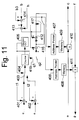
- Fig. 11 shows a specific configuration of the suppression increase/decrease circuit 615, Fig. 7.
- the circuit 615 is used to guarantee the howling margin up to the step in which the amounts of cancellation of the echo cancellers 603 and 612 are guaranteed (echo estimation procedure).
- subtracters 414 and 413 respectively subtract inputs b and h from the level comparators 614 an 611 from a constant b3, thereby calculating a necessary amount of suppression.
- a decision circuit 405 determines a speech direction and causes a switch 403 to select a particular criterion for determining a speech direction.
- the switch 403 selects the output of a subtracter 401 which subtracts a threshold value t1 from the output d of the comparison and decision circuit 605.
- the switch 403 selects the output of a subtracter 402 which subtracts a threshold value t2 from the output e of the comparison and decision circuit 609.
- a counter 404 is incremented or decremented on the basis of the output of the switch 403.
- the decision circuit 405 determines a speech direction on the basis of the value of the counter 404.
- a switch 415 is operated by the resulting output of the decision circuit 405.
- An adder 416 selectively increments or decrements an address pointer 406 in response to a constant q1 or q2 (e.g. +1 or -1) selected by the switch 415.
- a constant q1 or q2 e.g. +1 or -1 selected by the switch 415.
- the output of the adder 413 which is the amount of suppression necessary for the howling margin is used as the maximum value; when the value exceeds the maximum value, a switch 417 selects the maximum value.
- the address of a memory 408 is determined by the value selected by the switch 417.
- a multiplier 411 suppresses the signal with the output of the memory 408.
- an adder 412 produces a difference between the above maximum value and the output of the adder 416.
- An address pointer 407 determines the address of a memory 409 in response to the output of the adder 412. As a result, a multiplier 410 executes suppression with the output of the memory 409. The total amount of suppression effected by the two multipliers 410 and 411 corresponds to the above maximum value at all times. With this value, it is possible to guarantee the howling margin of the system.
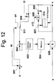
- FIG 12 shows a specific construction of the suppression increase/decrease circuit 616.
- the circuit 615 performs an auxiliary operation with the residual echo left in the channel transmission direction after the operation of the suppression increase/decrease circuit 615.
- the residual echo is greater at the acoustic side than at the channel side, i.e., the amount of cancellation available with the echo canceller at the acoustic side is smaller than the amount available with the echo canceller at the channel side.
- This is attributable to, for example, nonlinear transmission particular to the echo path at the acoustic side, and the variation of the echo path which is comparatively great. Specifically, as shown in Fig.
- a subtracter 501 subtracts a threshold value t4 from the output b of the comparison and decision circuit 605 so as to determine whether or not to execute suppression.
- the threshold value t4 is selected to be greater than the threshold value t1 of the circuit 615. With the difference between the threshold values t4 and t1, it is possible for each the circuits 615 and 616 to execute a particular decision.
- a switch 511 is operated by the output of the subtracter 501 and selects a criterion for varying an address pointer 503. When suppression should be reduced, an adder 502 varies an address pointer 503 in the direction for reducing suppression by a negative constant q4.
- the switch 511 selects the output of the subtracter 506 and thereby controls the suppressed level to a given value t3.
- a mean circuit 507 detects the suppressed signal level.
- a subtracter 506 subtracts a given level t3 from the detected signal level.
- the resulting output of the subtracter 506 is fed back to the address pointer 503 via the adder 502.
- the adder 502 varies the address pointer 503. As a result, a value to multiply is output from the memory 504.
Landscapes
- Engineering & Computer Science (AREA)
- Signal Processing (AREA)
- Cable Transmission Systems, Equalization Of Radio And Reduction Of Echo (AREA)
- Telephone Function (AREA)
- Filters That Use Time-Delay Elements (AREA)
Applications Claiming Priority (2)
| Application Number | Priority Date | Filing Date | Title |
|---|---|---|---|
| JP274128/94 | 1994-11-09 | ||
| JP6274128A JP2765494B2 (ja) | 1994-11-09 | 1994-11-09 | 2線式音声会議装置 |
Publications (1)
| Publication Number | Publication Date |
|---|---|
| EP0725527A1 true EP0725527A1 (de) | 1996-08-07 |
Family
ID=17537414
Family Applications (1)
| Application Number | Title | Priority Date | Filing Date |
|---|---|---|---|
| EP95117690A Withdrawn EP0725527A1 (de) | 1994-11-09 | 1995-11-09 | Sprachkonferenz-Echokompensatorsystem |
Country Status (4)
| Country | Link |
|---|---|
| US (1) | US5737408A (de) |
| EP (1) | EP0725527A1 (de) |
| JP (1) | JP2765494B2 (de) |
| CA (1) | CA2162538C (de) |
Cited By (1)
| Publication number | Priority date | Publication date | Assignee | Title |
|---|---|---|---|---|
| GB2312600B (en) * | 1996-04-24 | 2001-01-10 | Nec Corp | Audio apparatus |
Families Citing this family (11)
| Publication number | Priority date | Publication date | Assignee | Title |
|---|---|---|---|---|
| GB2330745B (en) * | 1997-10-24 | 2002-08-21 | Mitel Corp | Nonlinear processor for acoustic echo canceller |
| US6799062B1 (en) * | 2000-10-19 | 2004-09-28 | Motorola Inc. | Full-duplex hands-free transparency circuit and method therefor |
| US20040001597A1 (en) * | 2002-07-01 | 2004-01-01 | Tandberg Asa | Audio communication system and method with improved acoustic characteristics |
| US7599432B2 (en) * | 2003-12-08 | 2009-10-06 | Freescale Semiconductor, Inc. | Method and apparatus for dynamically inserting gain in an adaptive filter system |
| US7835774B1 (en) | 2006-09-12 | 2010-11-16 | Avaya Inc. | Removal of local duplication voice on conference calls |
| US7860236B2 (en) * | 2007-02-01 | 2010-12-28 | Hewlet-Packard Company | Method and system for echo cancellation in a network switch |
| US20090012786A1 (en) * | 2007-07-06 | 2009-01-08 | Texas Instruments Incorporated | Adaptive Noise Cancellation |
| US8411871B2 (en) * | 2007-08-22 | 2013-04-02 | Lantiq Deutschland Gmbh | Echo cancellation |
| JP5161838B2 (ja) * | 2009-05-18 | 2013-03-13 | 株式会社日立製作所 | エコーキャンセラおよび音響エコー消去方法 |
| WO2013142723A1 (en) | 2012-03-23 | 2013-09-26 | Dolby Laboratories Licensing Corporation | Hierarchical active voice detection |
| EP3667662B1 (de) * | 2018-12-12 | 2022-08-10 | Panasonic Intellectual Property Corporation of America | Vorrichtung zur unterdrückung von akustischem echo, verfahren zur unterdrückung von akustischem echo und programm zur unterdrückung von akustischem echo |
Citations (2)
| Publication number | Priority date | Publication date | Assignee | Title |
|---|---|---|---|---|
| EP0366584A2 (de) * | 1988-10-26 | 1990-05-02 | Rolm Company | Vollduplex-digitaler Lautfernsprecher |
| US5353348A (en) * | 1993-05-14 | 1994-10-04 | Jrc International, Inc. | Double echo cancelling system |
Family Cites Families (9)
| Publication number | Priority date | Publication date | Assignee | Title |
|---|---|---|---|---|
| US4629829A (en) * | 1984-12-14 | 1986-12-16 | Motorola, Inc. | Full duplex speakerphone for radio and landline telephones |
| JPH063950B2 (ja) * | 1985-02-28 | 1994-01-12 | 株式会社東芝 | 拡声電話装置 |
| JP2785336B2 (ja) * | 1989-06-13 | 1998-08-13 | 日本電気株式会社 | 音響エコーキャンセラのトレーニング方式 |
| FR2651077B1 (fr) * | 1989-08-18 | 1994-06-10 | Letourneur Gregoire | Dispositif de traitement d'echo notamment acoustique dans une ligne telephonique |
| CA2001277C (en) * | 1989-10-24 | 1994-07-12 | Bruce Leigh Townsend | Hands free telecommunications apparatus and method |
| US5075687A (en) * | 1990-09-27 | 1991-12-24 | Advanced Micro Devices, Inc. | Echo suppression with both digital and analog variable attenuators |
| US5313498A (en) * | 1991-06-13 | 1994-05-17 | Nec Corporation | Method and arrangement of echo elimination in digital telecommunications system |
| US5365583A (en) * | 1992-07-02 | 1994-11-15 | Polycom, Inc. | Method for fail-safe operation in a speaker phone system |
| JPH06104970A (ja) * | 1992-09-18 | 1994-04-15 | Fujitsu Ltd | 拡声電話機 |
-
1994
- 1994-11-09 JP JP6274128A patent/JP2765494B2/ja not_active Expired - Fee Related
-
1995
- 1995-11-09 EP EP95117690A patent/EP0725527A1/de not_active Withdrawn
- 1995-11-09 CA CA002162538A patent/CA2162538C/en not_active Expired - Fee Related
- 1995-11-09 US US08/552,503 patent/US5737408A/en not_active Expired - Fee Related
Patent Citations (2)
| Publication number | Priority date | Publication date | Assignee | Title |
|---|---|---|---|---|
| EP0366584A2 (de) * | 1988-10-26 | 1990-05-02 | Rolm Company | Vollduplex-digitaler Lautfernsprecher |
| US5353348A (en) * | 1993-05-14 | 1994-10-04 | Jrc International, Inc. | Double echo cancelling system |
Non-Patent Citations (1)
| Title |
|---|
| J.R. CASAR CORREDERA ET AL.: "A System for Acoustic Echo Control", SIGNAL PROCESSING V THEORIES AND APPLICATIONS PROCEEDINGS OF EUSIPCO-90, vol. iii, 18 September 1990 (1990-09-18) - 21 September 1990 (1990-09-21), BARCELONA, SPAIN, XP000365948 * |
Cited By (2)
| Publication number | Priority date | Publication date | Assignee | Title |
|---|---|---|---|---|
| GB2312600B (en) * | 1996-04-24 | 2001-01-10 | Nec Corp | Audio apparatus |
| US6215880B1 (en) | 1996-04-24 | 2001-04-10 | Nec Corporation | Two-wire conference apparatus with echo canceler without training |
Also Published As
| Publication number | Publication date |
|---|---|
| JPH08139647A (ja) | 1996-05-31 |
| CA2162538A1 (en) | 1996-05-10 |
| CA2162538C (en) | 2001-08-07 |
| JP2765494B2 (ja) | 1998-06-18 |
| US5737408A (en) | 1998-04-07 |
Similar Documents
| Publication | Publication Date | Title |
|---|---|---|
| JP3288383B2 (ja) | エコー経路変化の検出方法およびエコー・キャンセラ | |
| US6532289B1 (en) | Method and device for echo suppression | |
| JP2626437B2 (ja) | 残留エコー制御装置 | |
| JPH06188789A (ja) | 双方向通話状態検出回路 | |
| JP3139405B2 (ja) | エコーキャンセラ | |
| JP2001077729A (ja) | 自動利得制御器 | |
| US5737408A (en) | Echo cancelling system suitable for voice conference | |
| JPWO2000051262A1 (ja) | ダブルトーク検知装置、ダブルトーク検知装置を用いたエコーキャンセラ及びダブルトーク検知装置を用いたエコーサプレッサ | |
| US7231036B2 (en) | Anti-howling circuit detecting howling from effect of predicted echo signal | |
| US6215880B1 (en) | Two-wire conference apparatus with echo canceler without training | |
| US6185299B1 (en) | Adaptive echo cancellation device in a voice communication system | |
| EP1560348B1 (de) | Verfahren zur Wahrnehmung von Echopfadaenderungen in Echokompensatoren | |
| JP4475155B2 (ja) | エコーキャンセラ | |
| JPH07226697A (ja) | 反響消去装置、反響消去方法及び反響消去装置を有する送受話器 | |
| JP3248551B2 (ja) | 反響消去装置 | |
| US7724893B2 (en) | Method of adaptation step control in echo cancellers | |
| JP3187716B2 (ja) | 反響消去装置 | |
| JP2516260B2 (ja) | エコ―キャンセラ | |
| JP3094634B2 (ja) | エコー除去方法及びエコー除去装置 | |
| JPH09148966A (ja) | エコーキャンセラ | |
| JPH0821881B2 (ja) | エコ−キヤンセラのダブルト−ク検出制御方法 | |
| JPH07226699A (ja) | 反響消去装置 | |
| JP3403891B2 (ja) | 反響消去装置 | |
| JPS61161033A (ja) | 反響消去装置 | |
| JPS61161034A (ja) | 反響消去装置 |
Legal Events
| Date | Code | Title | Description |
|---|---|---|---|
| PUAI | Public reference made under article 153(3) epc to a published international application that has entered the european phase |
Free format text: ORIGINAL CODE: 0009012 |
|
| 17P | Request for examination filed |
Effective date: 19960328 |
|
| AK | Designated contracting states |
Kind code of ref document: A1 Designated state(s): DE FR GB |
|
| 17Q | First examination report despatched |
Effective date: 20010619 |
|
| STAA | Information on the status of an ep patent application or granted ep patent |
Free format text: STATUS: THE APPLICATION IS DEEMED TO BE WITHDRAWN |
|
| 18D | Application deemed to be withdrawn |
Effective date: 20040602 |