EP0725564B1 - Rundwirkmaschine - Google Patents
Rundwirkmaschine Download PDFInfo
- Publication number
- EP0725564B1 EP0725564B1 EP93902266A EP93902266A EP0725564B1 EP 0725564 B1 EP0725564 B1 EP 0725564B1 EP 93902266 A EP93902266 A EP 93902266A EP 93902266 A EP93902266 A EP 93902266A EP 0725564 B1 EP0725564 B1 EP 0725564B1
- Authority
- EP
- European Patent Office
- Prior art keywords
- treatment
- eccentrics
- groove
- pair
- rounder
- Prior art date
- Legal status (The legal status is an assumption and is not a legal conclusion. Google has not performed a legal analysis and makes no representation as to the accuracy of the status listed.)
- Expired - Lifetime
Links
- 230000001360 synchronised effect Effects 0.000 claims abstract description 6
- 235000013312 flour Nutrition 0.000 claims description 2
- 230000001105 regulatory effect Effects 0.000 claims description 2
- 241000209140 Triticum Species 0.000 description 2
- 235000021307 Triticum Nutrition 0.000 description 2
- 235000008429 bread Nutrition 0.000 description 2
- 238000005452 bending Methods 0.000 description 1
- 238000001125 extrusion Methods 0.000 description 1
- 238000011144 upstream manufacturing Methods 0.000 description 1
Images

Classifications
-
- A—HUMAN NECESSITIES
- A21—BAKING; EDIBLE DOUGHS
- A21C—MACHINES OR EQUIPMENT FOR MAKING OR PROCESSING DOUGHS; HANDLING BAKED ARTICLES MADE FROM DOUGH
- A21C7/00—Machines which homogenise the subdivided dough by working other than by kneading
- A21C7/01—Machines which homogenise the subdivided dough by working other than by kneading with endless bands
Definitions
- the present invention relates to a groove rounder, which is especially intended for a rye dough.
- the device comprises a treatment table and a frame thereof as well as two treatment elements moving in contact with an upper surface of the treatment table and arranged parallelly in a longitudinal direction of the treatment table, for performing a groove-rounding operation.
- Each treatment element is by means of two transverse arms joined to its own pair of eccentrics rotating on vertical shafts, of which one pair of eccentrics is larger than the other pair of eccentrics, and which pairs of eccentrics are arranged to rotate at an equal and similarly oriented rotational speed thus providing for both treatment elements an operational movement, which follows a circular path and maintains the longitudinal position of the treatment elements.
- the DE publication 27 06 495 describes a groove rounder developed for a wheat dough, in which the treatment elements are comprised of two plates moving at exactly the same rate and placed in a slanting position such that they diverge from each other at their upper ends.
- Such a design is in no way suitable for a sticky and wet rye dough, which is very difficult to treat, as is well known.
- a conveyor belt is not used, whereby the advancement of a lump of dough occurs in a direction defined by a treatment element driven by the larger pair of eccentrics.
- the object of the present invention is the realization of a groove rounder intended for a rye dough and operating as properly as possible.
- This object has been achieved by means of a groove rounder, which is characterized in that the groove rounder contains an endless conveyor belt moving in a longitudinal direction of the treatment table, on top of which belt the treatment elements in the form of troughs, open against each other, move, whereby the pairs of eccentrics are arranged to rotate in such a direction that the treatment trough driven by the larger pair of eccentrics moves against the travelling direction of the conveyor belt when being in the vicinity of the central line of the conveyor belt, and that the movements of the treatment troughs are synchronized with each other such that both treatment troughs at least momentarily move together towards each other and correspondingly away from each other.
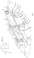
- the groove rounder comprises a treatment table 1 and a frame thereof, an endless conveyor belt 2 moving in the longitudinal direction of the treatment table as well as treatment elements 3 moving in contact with its upper surface and performing a groove-rounding operation, which elements 3 according to the invention comprise two treatment troughs 3 arranged in the longitudinal direction of the conveyor belt 2 parallelly and open against each other.
- Each treatment trough 3 is by means of two transverse arms 4 joined to its own pair of eccentrics 7; 8 rotating on vertical shafts 5; 6.
- One pair of eccentrics 7 is larger than the other pair of eccentrics 8, but all eccentrics 7; 8 are arranged to rotate at an equal and similarly oriented rotational speed.
- the eccentrics of the pair of eccentrics 7;8 rotate at the same rate thus providing for the treatment troughs 3 an operational movement, which follows a circular path and maintains the longitudinal position of the treatment troughs 3.
- the eccentrics 7; 8 are caused to rotate in the direction shown in the drawing by arrows such that the treatment trough 3 of the larger pair of eccentrics 7 moves against the travelling direction of the conveyor belt 2 driven by a separate driving device, when being in the vicinity of the central line of the conveyor belt 2.
- the movements of the treatment troughs 3 are synchronized with each other such that both treatment troughs 3 at least momentarily move together towards each other and correspondingly away from each other.
- the pairs of eccentrics 7, 8 are driven by a common speed-regulated motor, preferably an electric motor, whose driving power is transmitted to the eccentrics 7, 8 e.g. by means of an endless cogged belt 13 or a chain travelling over chain wheels 9, 10 fixed to their vertical shafts 5, 6 and a chain wheel 12 fixed to the drive shaft of the motor 11.
- a common speed-regulated motor preferably an electric motor, whose driving power is transmitted to the eccentrics 7, 8 e.g. by means of an endless cogged belt 13 or a chain travelling over chain wheels 9, 10 fixed to their vertical shafts 5, 6 and a chain wheel 12 fixed to the drive shaft of the motor 11.
- the inner surfaces of the treatment troughs 3 are preferably coated with a felt-like material, which prevents the sticky rye dough from adhering to the treatment troughs 3 and simultaneously creates as good a groove-rounding operation as possible.
- a flour spreading device is mounted at the inlet end of the groove rounder upstream of the batching device.
- the groove-rounding operation may further be intensified by placing the plane of the treatment table 1 such that it slightly ascends in the travelling direction of the conveyor belt 2 such that the dough lumps 14 are caused to move uphill during the groove-rounding operation.
- the groove rounder operates such that the dough lumps 14 individually batched onto the conveyor belt 2 move into a treatment station between the treatment troughs 3 moving together with the conveyor belt 2, at which station the groove-rounding operation occurs.
- the collision of the dough lumps 14 with the ends of the treatment troughs 3 may be efficiently prevented e.g. by bending the inlet ends of the treatment troughs slightly outwards towards the edges of the conveyor belt 2.
- the treatment troughs 3 affect the dough lump such that the treatment trough 3 of the larger pair of eccentrics 7 pushes the dough lump 14 diagonally towards the other treatment trough 3, simultaneously rotating the dough lump 14 in a direction slightly opposite to the rotational direction of the eccentrics 7, 8.
- the movement of the treatment trough 3 driven by the smaller pair of eccentrics 8 affects such that the dough lump is somewhat compressed so that as large a part of the dough lump as possible enters into contact with the inner surfaces of the treatment troughs 3 at the same time as it advances the rotation of the dough lump 14.
- the speed of the conveyor belt 2 and the rotational speed of the eccentrics 7, 8 as well as the sizes of both pairs of eccentrics have to be proportioned relative to each other such that the rotational shaft of the dough lumps intersects during the groove-rounding operation the lower edge or lower portion of the treatment trough 3 driven by the larger pair of eccentrics 7, when the trough 3 is in the step 3 of Fig.
- the outlet end of the treatment trough 3 driven by the pair of eccentrics 8 is preferably slightly bent outwards towards the edges of the conveoyr belt 2.
- the movements of the conveyor belt 2 and the eccentrics 7, 8 have preferably to be proportioned such that the eccentrics rotate e.g. by 20 revolutions during the time when the dough lump transfers through the treatment station.
- the pairs of eccentrics 7, 8 have to be preferably synchronized such that there is a small delay between both treatment troughs 3, as shown e.g. in the drawing, whereby the treatment trough 3 driven by the pair of eccentrics 8 reaches its extreme position by a delay of 25-30° relative to the treatment trough 3 driven by the pair of eccentrics 7.
- the treatment troughs 3 of the groove rounder are shown in the step 1 in a position, wherein the treatment trough 3 driven by the larger pair of eccentrics 7 is located farthermost from the central line of the conveyor belt 2 and the treatment trough 3 driven by the smaller pair of eccentrics 8 is at a distance of ca. 30° from this extreme position.
- the treatment trough driven by the pair of eccentrics 7 has advanced halfway on it travel towards the central line of the conveyor belt 2, and the treatment trough 3 driven by the pair of eccentrics 8 is located at a distance of ca. 30° from its corresponding position.
- the treatment trough 3 driven by the pair of eccentrics 7 has on its part reached its position located closest to the central line of the conveyor belt 2, and the treatment trough 3 driven by the pair of eccentrics 8 is located at a distance of ca. 30° from its corresponding extreme position
- the treatment trough 3 driven by the pair of eccentrics 7 has been reversed halfway on its travel away from the central line of the conveyor belt 2, and the treatment trough 3 driven by the pair of eccentrics 3 is located at a distance of ca. 30° from its corresponding position. From the point of view of the groove-rounding operation, the transfer of the treatment troughs from the position shown in the step 1 to the position shown in the step 2 and further to the position shown in the step 3 and 4 is extremely preferable.
- the treatment troughs 3 are in a vertical plane articulately fixed to the transverse arms 4.
- the inclination angle of the treatment troughs 3 may be adjusted such that above-mentioned preferable inclination of the rotational shaft of the dough lumps 14 is reached, as shown in Fig. 1a.
- the angle ⁇ of the rotational shaft and the vertical plane is preferably in the region 5-15°.
- the length of the transverse arms 4 is adjustable.
- the sizes of the eccentrics 7, 8 are steplessly adjustable.
Landscapes
- Life Sciences & Earth Sciences (AREA)
- Engineering & Computer Science (AREA)
- Food Science & Technology (AREA)
- Manufacturing And Processing Devices For Dough (AREA)
- Food-Manufacturing Devices (AREA)
Claims (10)
- Kanal-Rundwirkmaschine, insbesondere für Roggenteig, mit einem Behandlungstisch (1) und einem Gestell dafür sowie zwei Behandlungselementen (3), die sich mit einer oberen Oberfläche des Behandlungstisches in Berührung stehend bewegen und parallel zueinander in Längsrichtung des Behandlungstisches (1) angeordnet sind, um eine Kanal-Rundformung zu bewirken, wobei jedes Behandlungselement (3) durch zwei Querarme (4) mit seinem eigenen Exzenterpaar (7; 8) verbunden ist, deren Exzenter auf vertikalen Wellen (5; 6) rotieren, wobei das eine Exzenterpaar (7) größer als das andere Exzenterpaar (8) ist und die Exzenterpaare (7, 8) mit gleicher Drehzahl und ähnlicher Drehrichtung drehbar sind, so daß sich bei beiden Behandlungselementen (3) eine Arbeitsbewegung ergibt, die auf einer Kreisbahn verläuft und die in Längsrichtung ausgerichtete Lage der Behandlungselemente (3) beibehält, dadurch gekennzeichnet, daß die Kanal-Rundwirkmaschine ein endloses Förderband (2) aufweist, auf dem sich die Behandlungselemente (3) in Form von mit ihren Öffnungen einander zugekehrten Trögen bewegen, wobei die Exzenterpaare (7, 8) in einer solchen Richtung drehbar sind, daß sich der durch das größere Exzenterpaar (7) angetriebene Behandlungstrog (3) gegen die Laufrichtung des Förderbands (2) bewegt, wenn er sich in der Nähe der Mittellinie des Förderbands (2) befindet, und daß die Bewegungen der Behandlungströge (3) so miteinander synchronisiert sind, daß sich die beiden Behandlungströge (3) zumindest kurzzeitig zusammen zueinander hin und entsprechend voneinander weg bewegen.
- Kanal-Rundwirkmaschine nach Anspruch 1, dadurch gekennzeichnet, daß die Exzenterpaare (7, 8) durch einen drehzahlgeregelten Motor (11) angetrieben sind, dessen Antriebsleistung über einen endlosen Zahnriemen (13) oder eine Kette, die über auf vertikalen Wellen (5, 6) befestigte Kettenräder (9, 10) und ein auf der Antriebswelle des Motors (11) befestigtes Kettenrad (12) läuft, auf die Exzenter (7, 8) übertragen wird.
- Kanal-Rundwirkmaschine nach Anspruch 1, dadurch gekennzeichnet, daß die Exzenterpaare (7, 8) so synchronisiert sind, daß der durch das kleinere Exzenterpaar (8) angetriebene Behandlungstrog (3) seine extreme Lage mit einer Verzögerung von etwa 25 bis 30° gegenüber dem durch das größere Exzenterpaar (7) angetriebenen Behandlungstrog (3) erreicht.
- Kanal-Rundwirkmaschine nach Anspruch 1 oder 3, dadurch gekennzeichnet, daß die Ebene des Behandlungstisches (1) in Laufrichtung des Förderbands (2) ansteigt.
- Kanal-Rundwirkmaschine nach Anspruch 4, dadurch gekennzeichnet, daß die inneren Oberflächen der Behandlungströge (3) mit einem filzartigen Material überzogen sind.
- Kanal-Rundwirkmaschine nach Anspruch 5, dadurch gekennzeichnet, daß die Einlaßenden der Behandlungströge (3) und das Auslaßende des durch das kleinere Exzenterpaar (8) angetriebenen Behandlungstrogs (3) nach außen gebogen sind.
- Kanal-Rundwirkmaschine nach einem der vorstehenden Ansprüche, dadurch gekennzeichnet, daß die Behandlungströge (3) in einer vertikalen Ebene gelenkig an den Querarmen (4) zur Einstellung des Neigungswinkels der Behandlungströge (3) befestigt sind.
- Kanal-Rundwirkmaschine nach Anspruch 7, dadurch gekennzeichnet, daß der Neigungswinkel so eingestellt ist, daß der Winkel (α) zwischen der Vertikalebene und der Drehachse des zu behandelnden Teigklumpens im Bereich von 5 bis 15° liegt.
- Kanal-Rundwirkmaschine nach Anspruch 8, dadurch gekennzeichnet, daß am Einlaßende des Behandlungstisches (1) eine Beschickungsvorrichtung für Teigklumpen (14) sowie eine Mehlsprühvorrichtung angeordnet sind.
- Kanal-Rundwirkmaschine nach einem der vorstehenden Ansprüche, dadurch gekennzeichnet, daß die Länge der Querarme (4) einstellbar ist.
Applications Claiming Priority (3)
| Application Number | Priority Date | Filing Date | Title |
|---|---|---|---|
| FI920181A FI90492C (fi) | 1992-01-15 | 1992-01-15 | Riivari |
| FI920181 | 1992-01-15 | ||
| PCT/FI1993/000011 WO1993013667A1 (en) | 1992-01-15 | 1993-01-15 | Groove rounder |
Publications (2)
| Publication Number | Publication Date |
|---|---|
| EP0725564A1 EP0725564A1 (de) | 1996-08-14 |
| EP0725564B1 true EP0725564B1 (de) | 1999-04-21 |
Family
ID=8534009
Family Applications (1)
| Application Number | Title | Priority Date | Filing Date |
|---|---|---|---|
| EP93902266A Expired - Lifetime EP0725564B1 (de) | 1992-01-15 | 1993-01-15 | Rundwirkmaschine |
Country Status (4)
| Country | Link |
|---|---|
| EP (1) | EP0725564B1 (de) |
| DE (1) | DE69324613T2 (de) |
| FI (1) | FI90492C (de) |
| WO (1) | WO1993013667A1 (de) |
Families Citing this family (5)
| Publication number | Priority date | Publication date | Assignee | Title |
|---|---|---|---|---|
| ES2128885B1 (es) * | 1994-02-17 | 2001-03-16 | Martinez Eulalia Puig | Maquina heñidora de porciones de masa de pan. |
| JP3077903B2 (ja) | 1997-11-06 | 2000-08-21 | レオン自動機株式会社 | 食品生地搬送方法及び装置 |
| US6123537A (en) * | 1998-01-20 | 2000-09-26 | Cummins Eagle, Inc. | Rounder bar for processing bakery dough |
| DE10107406C2 (de) * | 2001-02-14 | 2003-07-17 | Helmut Schaefer | Maschine zum Rundformen von Teigstücken |
| JP6539435B2 (ja) * | 2013-11-29 | 2019-07-03 | レオン自動機株式会社 | 食品生地の丸め成形装置及び丸め成形方法 |
Family Cites Families (2)
| Publication number | Priority date | Publication date | Assignee | Title |
|---|---|---|---|---|
| DE1073981B (de) * | 1960-01-28 | Rossignol Luxemburg Marcel Clausse (Belgien) | Maschine zum Wirken von Rundbroten | |
| NL7601680A (nl) * | 1976-02-19 | 1977-08-23 | Benier Bv | Opbolmachine. |
-
1992
- 1992-01-15 FI FI920181A patent/FI90492C/fi not_active IP Right Cessation
-
1993
- 1993-01-15 EP EP93902266A patent/EP0725564B1/de not_active Expired - Lifetime
- 1993-01-15 DE DE69324613T patent/DE69324613T2/de not_active Expired - Fee Related
- 1993-01-15 WO PCT/FI1993/000011 patent/WO1993013667A1/en not_active Ceased
Also Published As
| Publication number | Publication date |
|---|---|
| FI920181A7 (fi) | 1993-07-16 |
| DE69324613D1 (de) | 1999-05-27 |
| FI920181A0 (fi) | 1992-01-15 |
| WO1993013667A1 (en) | 1993-07-22 |
| EP0725564A1 (de) | 1996-08-14 |
| DE69324613T2 (de) | 1999-10-14 |
| FI90492B (fi) | 1993-11-15 |
| FI90492C (fi) | 1994-02-25 |
Similar Documents
| Publication | Publication Date | Title |
|---|---|---|
| US4113412A (en) | Apparatus for forming dough pieces | |
| US4192636A (en) | Apparatus for stretching dough material | |
| CA1255155A (en) | Apparatus for stretching plastic dough | |
| KR100303905B1 (ko) | 빵 반죽 등의 스트래칭 장치 | |
| AU2013272820B2 (en) | Food dough rounding device and food dough rounding method | |
| EP0725564B1 (de) | Rundwirkmaschine | |
| US5375509A (en) | Dough ball preparation table | |
| US4435144A (en) | Apparatus for shaping dough | |
| US6248384B1 (en) | Method for forming a spherical dough body | |
| US5272962A (en) | Method and apparatus for producing a sheet of dough | |
| US5182124A (en) | Method and apparatus for producing a sheet of dough | |
| US3494303A (en) | Food processing system | |
| AU614903B2 (en) | A dough-twisting machine | |
| FI103318B (fi) | Riivari | |
| JP3054766B2 (ja) | 食品生地搬送方法及び装置 | |
| US3990685A (en) | Kneading apparatus for breadmaking | |
| US2136487A (en) | Bread loaf forming machine | |
| CN210445476U (zh) | 饼坯制作装置 | |
| US4191519A (en) | Dough-rounding machine | |
| JP7011436B2 (ja) | 棒状食材の供給方法及び棒状食材の供給装置 | |
| US3370555A (en) | Dough working apparatus | |
| US20240215589A1 (en) | Cleaning device for extension roller | |
| KR20230167620A (ko) | 호떡 자동 성형 장치 | |
| JP2004248574A (ja) | 生地丸め成形装置 | |
| SU976921A1 (ru) | Тестоокруглительна машина |
Legal Events
| Date | Code | Title | Description |
|---|---|---|---|
| PUAI | Public reference made under article 153(3) epc to a published international application that has entered the european phase |
Free format text: ORIGINAL CODE: 0009012 |
|
| 17P | Request for examination filed |
Effective date: 19940718 |
|
| AK | Designated contracting states |
Kind code of ref document: A1 Designated state(s): DE DK SE |
|
| RAP1 | Party data changed (applicant data changed or rights of an application transferred) |
Owner name: LT-KONE OY |
|
| GRAG | Despatch of communication of intention to grant |
Free format text: ORIGINAL CODE: EPIDOS AGRA |
|
| 17Q | First examination report despatched |
Effective date: 19980804 |
|
| GRAG | Despatch of communication of intention to grant |
Free format text: ORIGINAL CODE: EPIDOS AGRA |
|
| GRAH | Despatch of communication of intention to grant a patent |
Free format text: ORIGINAL CODE: EPIDOS IGRA |
|
| GRAH | Despatch of communication of intention to grant a patent |
Free format text: ORIGINAL CODE: EPIDOS IGRA |
|
| GRAA | (expected) grant |
Free format text: ORIGINAL CODE: 0009210 |
|
| AK | Designated contracting states |
Kind code of ref document: B1 Designated state(s): DE DK SE |
|
| REF | Corresponds to: |
Ref document number: 69324613 Country of ref document: DE Date of ref document: 19990527 |
|
| PG25 | Lapsed in a contracting state [announced via postgrant information from national office to epo] |
Ref country code: DK Free format text: LAPSE BECAUSE OF FAILURE TO SUBMIT A TRANSLATION OF THE DESCRIPTION OR TO PAY THE FEE WITHIN THE PRESCRIBED TIME-LIMIT Effective date: 19990721 |
|
| PLBE | No opposition filed within time limit |
Free format text: ORIGINAL CODE: 0009261 |
|
| STAA | Information on the status of an ep patent application or granted ep patent |
Free format text: STATUS: NO OPPOSITION FILED WITHIN TIME LIMIT |
|
| 26N | No opposition filed | ||
| PGFP | Annual fee paid to national office [announced via postgrant information from national office to epo] |
Ref country code: SE Payment date: 20031230 Year of fee payment: 12 |
|
| PGFP | Annual fee paid to national office [announced via postgrant information from national office to epo] |
Ref country code: DE Payment date: 20040116 Year of fee payment: 12 |
|
| PG25 | Lapsed in a contracting state [announced via postgrant information from national office to epo] |
Ref country code: SE Free format text: LAPSE BECAUSE OF NON-PAYMENT OF DUE FEES Effective date: 20050116 |
|
| PG25 | Lapsed in a contracting state [announced via postgrant information from national office to epo] |
Ref country code: DE Free format text: LAPSE BECAUSE OF NON-PAYMENT OF DUE FEES Effective date: 20050802 |
|
| EUG | Se: european patent has lapsed |