EP0725657B1 - Blutsauerstoffsystem und herstellverfahren - Google Patents
Blutsauerstoffsystem und herstellverfahren Download PDFInfo
- Publication number
- EP0725657B1 EP0725657B1 EP94931845A EP94931845A EP0725657B1 EP 0725657 B1 EP0725657 B1 EP 0725657B1 EP 94931845 A EP94931845 A EP 94931845A EP 94931845 A EP94931845 A EP 94931845A EP 0725657 B1 EP0725657 B1 EP 0725657B1
- Authority
- EP
- European Patent Office
- Prior art keywords
- blood
- heat exchanging
- separation medium
- housing
- barrier
- Prior art date
- Legal status (The legal status is an assumption and is not a legal conclusion. Google has not performed a legal analysis and makes no representation as to the accuracy of the status listed.)
- Expired - Lifetime
Links
Images

















Classifications
-
- B—PERFORMING OPERATIONS; TRANSPORTING
- B01—PHYSICAL OR CHEMICAL PROCESSES OR APPARATUS IN GENERAL
- B01D—SEPARATION
- B01D63/00—Apparatus in general for separation processes using semi-permeable membranes
- B01D63/02—Hollow fibre modules
-
- A—HUMAN NECESSITIES
- A61—MEDICAL OR VETERINARY SCIENCE; HYGIENE
- A61M—DEVICES FOR INTRODUCING MEDIA INTO, OR ONTO, THE BODY; DEVICES FOR TRANSDUCING BODY MEDIA OR FOR TAKING MEDIA FROM THE BODY; DEVICES FOR PRODUCING OR ENDING SLEEP OR STUPOR
- A61M1/00—Suction or pumping devices for medical purposes; Devices for carrying-off, for treatment of, or for carrying-over, body-liquids; Drainage systems
- A61M1/14—Dialysis systems; Artificial kidneys; Blood oxygenators ; Reciprocating systems for treatment of body fluids, e.g. single needle systems for hemofiltration or pheresis
- A61M1/16—Dialysis systems; Artificial kidneys; Blood oxygenators ; Reciprocating systems for treatment of body fluids, e.g. single needle systems for hemofiltration or pheresis with membranes
- A61M1/1621—Constructional aspects thereof
- A61M1/1623—Disposition or location of membranes relative to fluids
- A61M1/1625—Dialyser of the outside perfusion type, i.e. blood flow outside hollow membrane fibres or tubes
-
- A—HUMAN NECESSITIES
- A61—MEDICAL OR VETERINARY SCIENCE; HYGIENE
- A61M—DEVICES FOR INTRODUCING MEDIA INTO, OR ONTO, THE BODY; DEVICES FOR TRANSDUCING BODY MEDIA OR FOR TAKING MEDIA FROM THE BODY; DEVICES FOR PRODUCING OR ENDING SLEEP OR STUPOR
- A61M1/00—Suction or pumping devices for medical purposes; Devices for carrying-off, for treatment of, or for carrying-over, body-liquids; Drainage systems
- A61M1/14—Dialysis systems; Artificial kidneys; Blood oxygenators ; Reciprocating systems for treatment of body fluids, e.g. single needle systems for hemofiltration or pheresis
- A61M1/16—Dialysis systems; Artificial kidneys; Blood oxygenators ; Reciprocating systems for treatment of body fluids, e.g. single needle systems for hemofiltration or pheresis with membranes
- A61M1/1621—Constructional aspects thereof
- A61M1/1629—Constructional aspects thereof with integral heat exchanger
-
- A—HUMAN NECESSITIES
- A61—MEDICAL OR VETERINARY SCIENCE; HYGIENE
- A61M—DEVICES FOR INTRODUCING MEDIA INTO, OR ONTO, THE BODY; DEVICES FOR TRANSDUCING BODY MEDIA OR FOR TAKING MEDIA FROM THE BODY; DEVICES FOR PRODUCING OR ENDING SLEEP OR STUPOR
- A61M1/00—Suction or pumping devices for medical purposes; Devices for carrying-off, for treatment of, or for carrying-over, body-liquids; Drainage systems
- A61M1/14—Dialysis systems; Artificial kidneys; Blood oxygenators ; Reciprocating systems for treatment of body fluids, e.g. single needle systems for hemofiltration or pheresis
- A61M1/16—Dialysis systems; Artificial kidneys; Blood oxygenators ; Reciprocating systems for treatment of body fluids, e.g. single needle systems for hemofiltration or pheresis with membranes
- A61M1/1698—Blood oxygenators with or without heat-exchangers
-
- A—HUMAN NECESSITIES
- A61—MEDICAL OR VETERINARY SCIENCE; HYGIENE
- A61M—DEVICES FOR INTRODUCING MEDIA INTO, OR ONTO, THE BODY; DEVICES FOR TRANSDUCING BODY MEDIA OR FOR TAKING MEDIA FROM THE BODY; DEVICES FOR PRODUCING OR ENDING SLEEP OR STUPOR
- A61M1/00—Suction or pumping devices for medical purposes; Devices for carrying-off, for treatment of, or for carrying-over, body-liquids; Drainage systems
- A61M1/36—Other treatment of blood in a by-pass of the natural circulatory system, e.g. temperature adaptation, irradiation ; Extra-corporeal blood circuits
- A61M1/3621—Extra-corporeal blood circuits
- A61M1/3623—Means for actively controlling temperature of blood
-
- A—HUMAN NECESSITIES
- A61—MEDICAL OR VETERINARY SCIENCE; HYGIENE
- A61M—DEVICES FOR INTRODUCING MEDIA INTO, OR ONTO, THE BODY; DEVICES FOR TRANSDUCING BODY MEDIA OR FOR TAKING MEDIA FROM THE BODY; DEVICES FOR PRODUCING OR ENDING SLEEP OR STUPOR
- A61M1/00—Suction or pumping devices for medical purposes; Devices for carrying-off, for treatment of, or for carrying-over, body-liquids; Drainage systems
- A61M1/36—Other treatment of blood in a by-pass of the natural circulatory system, e.g. temperature adaptation, irradiation ; Extra-corporeal blood circuits
- A61M1/3621—Extra-corporeal blood circuits
- A61M1/3627—Degassing devices; Buffer reservoirs; Drip chambers; Blood filters
-
- A—HUMAN NECESSITIES
- A61—MEDICAL OR VETERINARY SCIENCE; HYGIENE
- A61M—DEVICES FOR INTRODUCING MEDIA INTO, OR ONTO, THE BODY; DEVICES FOR TRANSDUCING BODY MEDIA OR FOR TAKING MEDIA FROM THE BODY; DEVICES FOR PRODUCING OR ENDING SLEEP OR STUPOR
- A61M1/00—Suction or pumping devices for medical purposes; Devices for carrying-off, for treatment of, or for carrying-over, body-liquids; Drainage systems
- A61M1/36—Other treatment of blood in a by-pass of the natural circulatory system, e.g. temperature adaptation, irradiation ; Extra-corporeal blood circuits
- A61M1/3621—Extra-corporeal blood circuits
- A61M1/3627—Degassing devices; Buffer reservoirs; Drip chambers; Blood filters
- A61M1/3632—Combined venous-cardiotomy reservoirs
-
- A—HUMAN NECESSITIES
- A61—MEDICAL OR VETERINARY SCIENCE; HYGIENE
- A61M—DEVICES FOR INTRODUCING MEDIA INTO, OR ONTO, THE BODY; DEVICES FOR TRANSDUCING BODY MEDIA OR FOR TAKING MEDIA FROM THE BODY; DEVICES FOR PRODUCING OR ENDING SLEEP OR STUPOR
- A61M60/00—Blood pumps; Devices for mechanical circulatory actuation; Balloon pumps for circulatory assistance
- A61M60/10—Location thereof with respect to the patient's body
- A61M60/104—Extracorporeal pumps, i.e. the blood being pumped outside the patient's body
- A61M60/109—Extracorporeal pumps, i.e. the blood being pumped outside the patient's body incorporated within extracorporeal blood circuits or systems
- A61M60/113—Extracorporeal pumps, i.e. the blood being pumped outside the patient's body incorporated within extracorporeal blood circuits or systems in other functional devices, e.g. dialysers or heart-lung machines
-
- A—HUMAN NECESSITIES
- A61—MEDICAL OR VETERINARY SCIENCE; HYGIENE
- A61M—DEVICES FOR INTRODUCING MEDIA INTO, OR ONTO, THE BODY; DEVICES FOR TRANSDUCING BODY MEDIA OR FOR TAKING MEDIA FROM THE BODY; DEVICES FOR PRODUCING OR ENDING SLEEP OR STUPOR
- A61M60/00—Blood pumps; Devices for mechanical circulatory actuation; Balloon pumps for circulatory assistance
- A61M60/20—Type thereof
- A61M60/205—Non-positive displacement blood pumps
- A61M60/216—Non-positive displacement blood pumps including a rotating member acting on the blood, e.g. impeller
- A61M60/226—Non-positive displacement blood pumps including a rotating member acting on the blood, e.g. impeller the blood flow through the rotating member having mainly radial components
- A61M60/232—Centrifugal pumps
-
- A—HUMAN NECESSITIES
- A61—MEDICAL OR VETERINARY SCIENCE; HYGIENE
- A61M—DEVICES FOR INTRODUCING MEDIA INTO, OR ONTO, THE BODY; DEVICES FOR TRANSDUCING BODY MEDIA OR FOR TAKING MEDIA FROM THE BODY; DEVICES FOR PRODUCING OR ENDING SLEEP OR STUPOR
- A61M60/00—Blood pumps; Devices for mechanical circulatory actuation; Balloon pumps for circulatory assistance
- A61M60/20—Type thereof
- A61M60/247—Positive displacement blood pumps
- A61M60/253—Positive displacement blood pumps including a displacement member directly acting on the blood
- A61M60/268—Positive displacement blood pumps including a displacement member directly acting on the blood the displacement member being flexible, e.g. membranes, diaphragms or bladders
- A61M60/279—Peristaltic pumps, e.g. roller pumps
-
- A—HUMAN NECESSITIES
- A61—MEDICAL OR VETERINARY SCIENCE; HYGIENE
- A61M—DEVICES FOR INTRODUCING MEDIA INTO, OR ONTO, THE BODY; DEVICES FOR TRANSDUCING BODY MEDIA OR FOR TAKING MEDIA FROM THE BODY; DEVICES FOR PRODUCING OR ENDING SLEEP OR STUPOR
- A61M60/00—Blood pumps; Devices for mechanical circulatory actuation; Balloon pumps for circulatory assistance
- A61M60/30—Medical purposes thereof other than the enhancement of the cardiac output
- A61M60/36—Medical purposes thereof other than the enhancement of the cardiac output for specific blood treatment; for specific therapy
- A61M60/38—Blood oxygenation
-
- A—HUMAN NECESSITIES
- A61—MEDICAL OR VETERINARY SCIENCE; HYGIENE
- A61M—DEVICES FOR INTRODUCING MEDIA INTO, OR ONTO, THE BODY; DEVICES FOR TRANSDUCING BODY MEDIA OR FOR TAKING MEDIA FROM THE BODY; DEVICES FOR PRODUCING OR ENDING SLEEP OR STUPOR
- A61M60/00—Blood pumps; Devices for mechanical circulatory actuation; Balloon pumps for circulatory assistance
- A61M60/80—Constructional details other than related to driving
- A61M60/845—Constructional details other than related to driving of extracorporeal blood pumps
- A61M60/851—Valves
-
- A—HUMAN NECESSITIES
- A61—MEDICAL OR VETERINARY SCIENCE; HYGIENE
- A61M—DEVICES FOR INTRODUCING MEDIA INTO, OR ONTO, THE BODY; DEVICES FOR TRANSDUCING BODY MEDIA OR FOR TAKING MEDIA FROM THE BODY; DEVICES FOR PRODUCING OR ENDING SLEEP OR STUPOR
- A61M1/00—Suction or pumping devices for medical purposes; Devices for carrying-off, for treatment of, or for carrying-over, body-liquids; Drainage systems
- A61M1/36—Other treatment of blood in a by-pass of the natural circulatory system, e.g. temperature adaptation, irradiation ; Extra-corporeal blood circuits
- A61M1/3621—Extra-corporeal blood circuits
-
- A—HUMAN NECESSITIES
- A61—MEDICAL OR VETERINARY SCIENCE; HYGIENE
- A61M—DEVICES FOR INTRODUCING MEDIA INTO, OR ONTO, THE BODY; DEVICES FOR TRANSDUCING BODY MEDIA OR FOR TAKING MEDIA FROM THE BODY; DEVICES FOR PRODUCING OR ENDING SLEEP OR STUPOR
- A61M2209/00—Ancillary equipment
- A61M2209/08—Supports for equipment
- A61M2209/082—Mounting brackets, arm supports for equipment
-
- B—PERFORMING OPERATIONS; TRANSPORTING
- B01—PHYSICAL OR CHEMICAL PROCESSES OR APPARATUS IN GENERAL
- B01D—SEPARATION
- B01D2313/00—Details relating to membrane modules or apparatus
- B01D2313/22—Cooling or heating elements
- B01D2313/221—Heat exchangers
-
- B—PERFORMING OPERATIONS; TRANSPORTING
- B01—PHYSICAL OR CHEMICAL PROCESSES OR APPARATUS IN GENERAL
- B01D—SEPARATION
- B01D2313/00—Details relating to membrane modules or apparatus
- B01D2313/50—Specific extra tanks
-
- Y—GENERAL TAGGING OF NEW TECHNOLOGICAL DEVELOPMENTS; GENERAL TAGGING OF CROSS-SECTIONAL TECHNOLOGIES SPANNING OVER SEVERAL SECTIONS OF THE IPC; TECHNICAL SUBJECTS COVERED BY FORMER USPC CROSS-REFERENCE ART COLLECTIONS [XRACs] AND DIGESTS
- Y10—TECHNICAL SUBJECTS COVERED BY FORMER USPC
- Y10S—TECHNICAL SUBJECTS COVERED BY FORMER USPC CROSS-REFERENCE ART COLLECTIONS [XRACs] AND DIGESTS
- Y10S128/00—Surgery
- Y10S128/13—Infusion monitoring
Definitions
- This invention relates generally to extracorporeal blood oxygenation systems, and more particularly to an integral blood oxygenation and heat exchanging apparatus and its method of manufacturing and an extra corporeal circulatory support circuit comprising such an apparatus.
- the reservoir comprises a housing having walls defining two interior chambers including a blood storage chamber and a defoaming and filtering chamber. Each chamber has a top and a bottom.
- the blood storage chamber and defoaming and filtering chamber are separated from one another by a generally vertical dividing wall formed of substantially liquid impervious material.
- the dividing wall has a vent generally adjacent the top of the defoaming and filtering chamber communicating with the blood storage chamber, and a port generally adjacent the bottom of the defoaming and filtering chamber communicating with the blood storage chamber.
- At least one cardiotomy blood inlet is provided communicating with the defoaming and filtering chamber for supplying scavenged blood to the reservoir, and at least one venous blood inlet communicating with the defoaming and filtering chamber.
- a blood filtering medium is provided in the defoaming and filtering chamber for filtering the blood to remove clots and other undesired matter from the blood.
- the blood filtering medium is positioned in the defoaming and filtering chamber such that blood entering the defoaming and filtering chamber from the cardiotomy blood inlet must pass through the blood filtering medium.
- a blood defoaming medium is also provided, which takes up substantially the entire space of the defoaming and filtering chamber not occupied by the filtering medium such that blood entering the defoaming and filtering chamber through the cardiotomy blood inlet and venous blood inlet must pass through the blood defoaming medium before exiting the defoaming and filtering chamber through the port.
- the blood filtering medium is positioned such that blood entering the defoaming and filtering chamber through the venous inlet does not pass through the blood filtering medium.
- the reservoir includes a generally vertically extending exterior wall forming, together with the dividing wall, the defoaming and filtering chamber, with the cardiotomy blood inlet or inlets being positioned on the exterior wall generally adjacent the top of the defoaming and filtering chamber, and the venous blood inlet or inlets being positioned on the exterior wall generally adjacent the bottom of the defoaming and filtering chamber.
- the walls of the reservoir are formed by thermal forming of thermoplastic material and sealing the walls together along peripheral portions thereof to form the chambers.
- An outlet is conveniently provided adjacent the bottom of the blood storage chamber communicating with the interior of the blood storage chamber for draining blood from the blood storage chamber.
- WO 90/07943 discloses a device comprising an oxygenator formed by gas permeable hollow fibers and a heat exchanger formed by a bundle of polyurethane, liquid impermeable hollow tubes.
- a center divider forms two separate compartments.
- the oxygenator and heat exchanger are enclosed within a housing, and the ends of the gas permeable hollow fibers and liquid impermeable hollow tubes are enclosed in end caps permanently secured to the housing.
- the end caps provide gas and heat exchange media inlets and outlets to the ends of the hollow fiber and tube bundles.
- an integral blood oxygenating and heat exchanging apparatus for oxygenating blood and heating or cooling blood.
- the blood oxygenating and heat exchanging apparatus comprises a blood oxygenating and heat exchanging device.
- the blood oxygenating and heat exchanging device comprises a separation medium (blood oxygenating medium).
- the separation medium or blood oxygenating medium comprises hollow fibers for separating blood and gas while permitting transfer of oxygen and carbon dioxide across the medium to oxygenate the blood.
- the separation medium is arranged in an array having opposite ends.
- a heat exchanging barrier is provided for separating blood and a heat-exchanging fluid while permitting heat transfer across the barrier to heat or cool the blood.
- the barrier has opposite ends positioned generally adjacent and generally aligned with the opposite ends of the separation medium.
- a housing holds the separation medium and the heat exchanging barrier.
- the housing can be formed of at least one sheet of thermoplastic material thermal formed into a configuration corresponding to the separation medium and the heat exchanging barrier Potting compound seals the housing adjacent the ends of the separation medium and heat exchanging barrier without closing their open ends.
- the potting compound can be applied by the following process: (a) spinning an assembly of the separation medium, heat exchanging barrier and housing in a centrifuge with the opposite ends of the separation medium and heat exchanging barrier on opposite sides of the axis of rotation of the centrifuge; (b) pouring uncured potting compound into the channels of the housing while the centrifuge is spinning to drive the potting compound toward the opposite ends of the separation medium and heat exchanging barrier; and (c) allowing the potting compound to solidify before stopping rotation of the housing, separation medium and heat exchanging medium in the centrifuge.
- a blood inlet and outlet are provided into the housing defining a blood flow path across the separation medium and heat exchanging barrier. The open ends of the hollow fibers and of the heat exchanging barrier open into the environment outside the housing.
- the separation medium and heat exchanging barrier have opposite surfaces defining the blood flow path and gas or heat-exchanging fluid paths, respectively.
- the device further comprises a gas inlet and outlet into the apparatus defining a gas flow path along the surface of the separation medium opposite the blood flow path; and a heat exchanging fluid inlet and outlet into the apparatus defining a heat exchanging fluid path along the surface of the heat exchanging barrier opposite the blood flow path.
- the housing includes opposite walls along opposite sides of the separation medium, with the blood flow path being defined between the opposite walls of the housing along one surface of the separation medium.
- the opposite walls are most preferably resiliently-flexible within a range of flexure to allow the opposite walls to be compressed toward one another to adjust oxygenation of blood flowing through the blood flow path.
- a mounting bracket is preferably provided for releasably receiving and supporting the device.
- the mounting bracket is configured to closely receive the device to support the weight of the device and support the housing of the device against internal pressure in the housing.
- the mounting bracket includes means for compressing the opposite walls of the housing toward one another to adjust oxygenation of blood flowing through the blood flow path.
- the mounting bracket also includes connections for bringing (a) the gas inlet of the device received in the mounting bracket into fluid communication with a source of gas, and (b) the heat exchanging fluid inlet and outlet of the device received in the mounting bracket into fluid communication with a source of heat exchanging fluid and a conduit for draining heat exchanging fluid, respectively.
- a second aspect of the invention is a method of forming an integral blood oxygenating and heat exchanging apparatus according to claim 5.
- the method comprises the following steps: (a) providing a separation medium for separating blood and gas from one another while allowing oxygen and carbon dioxide transfer across the separation medium, the separation medium having opposite ends; (b) providing a heat exchanging barrier for separating blood and heat exchanging fluid from one another while allowing heat transfer therebetween across the heat exchanging barrier, the heat exchanging barrier having opposite ends; (c) thermal forming at least one sheet of thermoplastic material to form a housing in configuration with the separation medium and heat exchanging barrier, the opposite ends of the separation medium and heat exchanging barrier being generally adjacent and generally aligned with one another, the housing forming a channel for directing potting compound adjacent the opposite ends of the separation medium and heat exchanging barrier; the sheet forming a blood inlet and a blood outlet to the housing; (d) placing the separation medium and the heat exchanging barrier between the sheets forming the housing; (e) sealing the sheets together to form an assembly comprising the housing
- a kiln is provided surrounding the centrifuge, and during the steps (g), (h) and (i), the assembly is heated in the kiln while the centrifuge spins the assembly until the potting compound is cured.
- an extracorporeal circulatory support circuit for supporting a patient during cardiopulmonary bypass.
- the circuit comprises a blood reservoir having a defoaming and filtering chamber and a blood storage chamber in fluid communication with the defoaming and filtering chamber.
- the reservoir has at least one cardiotomy blood inlet and at least one venous blood inlet into the defoaming and filtering chamber and an outlet for draining the blood storage chamber.
- the defoaming and filtering chamber includes defoaming and filtering mediums.
- a separation medium blood oxygenating medium
- is provided comprising hollow fibers for separating blood and gas while permitting transfer of oxygen and carbon dioxide across the medium to oxygenate the blood.
- the separation medium is arranged in an array having opposite ends.
- a heat exchanging barrier is provided for separating blood and a heat-exchanging fluid while permitting heat transfer across the barrier to heat or cool the blood.
- the barrier has opposite ends positioned generally adjacent and generally aligned with the opposite ends of the separation medium.
- a housing is provided having portions defining the blood reservoir and holding the separation medium and the heat exchanging barrier.
- the housing can be formed of at least one sheet of thermoplastic material thermal formed into a configuration corresponding to the reservoir, separation medium and heat exchanging barrier. Potting compound seals the housing adjacent the ends of the separation medium and heat exchanging barrier.
- the potting compound can be applied by the following process: (a) spinning an assembly of the separation medium, heat exchanging barrier and housing in a centrifuge with the opposite ends of the separation medium and heat exchanging barrier on opposite sides of the axis of rotation of the centrifuge; (b) pouring uncured potting compound into channels formed in the housing for directing potting compound toward the opposite ends of the separation medium and the heat exchanging barrier.
- a blood inlet and outlet are provided into the portion of the housing holding the separation medium and heat exchanging barrier.
- the blood inlet is in fluid communication with the blood outlet of the reservoir.
- the blood inlet and outlet define a blood flow path across the separation medium and heat exchanging barrier.
- a blood conduit is provided to bring the outlet of the reservoir into fluid communication with the blood inlet of the portion of the housing holding the separation medium and heat exchanging barrier.
- the blood conduit is adapted for pumping the blood through the blood conduit from the reservoir into the portion of the housing holding the separation medium and heat exchanging barrier.
- a centrifugal blood pump is mounted along the blood conduit to pump blood from the reservoir through the portion of the housing holding the separation medium and heat exchanging barrier.
- the sheet forming the housing also includes a portion holding the centrifugal blood pump.
- the centrifugal blood pump may be releaseably held on the sheet.
- the blood conduit is formed of resiliently flexible tubing which is adapted to be placed in a positive displacement roller pump to pump blood from the reservoir through the portion of the housing holding the separation medium and heat exchanging barrier.
- the separation medium and heat exchanging barrier have opposite surfaces defining the blood flow path and gas or heat-exchanging fluid paths, respectively.
- the circuit further comprises a gas inlet and outlet into the portion of the housing holding the separation medium and heat exchanging barrier.
- the gas inlet and outlet define a gas flow path along the surface of the separation medium opposite the blood flow path.
- a heat exchanging fluid inlet and outlet are provided into the portion of the housing holding the separation medium and heat exchanging barrier, with the heat exchanging fluid inlet and outlet defining a heat exchanging fluid path along the surface of the heat exchanging barrier opposite the blood flow path.
- the housing includes opposite walls along opposite sides of the separation medium, the blood flow path being defined between the opposite walls of the housing along one surface of the separation medium, the opposite walls being resiliently-flexible within a range of flexure to allow the opposite walls to be compressed toward one another to adjust oxygenation of blood flowing through the blood flow path.
- a mounting bracket is provided for releasably receiving and supporting the housing.
- the mounting bracket is configured to closely receive the portion of the housing holding the separation medium and heat exchanging barrier to support the weight of the housing and its contents and support the housing against internal pressure in the housing.
- the mounting bracket includes means for compressing the opposite walls of the housing toward one another to adjust oxygenation of blood flowing through the blood flow path.
- the mounting bracket includes connections for bringing (a) the gas inlet of the housing received in the mounting bracket into fluid communication with a source of gas, and (b) the heat exchanging fluid inlet and outlet of the housing received in the mounting bracket into fluid communication with a source of heat exchanging fluid and a conduit for draining heat exchanging fluid, respectively.
- the combination of a venous/cardiotomy blood reservoir and an oxygenating and heat exchanging device is designated in its entirety by the reference numeral 10.
- the combination 10 is adapted to be used to provide extracorporeal support to a patient on cardiopulmonary bypass.
- the combination 10 is also referred to herein as an integrated circuit (also 10) incorporating pre-connected components, including a venous/cardiotomy reservoir 12, a novel blood oxygenating and heat exchanging device 14, and a centrifugal blood pump 16.
- the circuit 10 is adapted for use with a bank 18 of roller pumps.
- Suitable centrifugal pumps 16 are shown in coassigned U.S. Patent Nos. 4,589,822; 4,606,698; 4,690,002; 4,778,445; 4,781,525 and 4,984,972, and are available under the trade designation "SARNSTM 7850TM centrifugal pump” from Minnesota Mining and Manufacturing Company, St. Paul, Minnesota, U.S.A.
- the arrangement of the circuit 10 is such that a venous line drains blood from the patient's venous system into the venous/cardiotomy blood reservoir 12, where the blood is defoamed and held, and the bank 18 of roller pumps may be used with cardiac suckers (not shown) to drain blood from the chest wound and deliver the scavenged blood to the cardiotomy portion of the reservoir 12. Blood is then pumped from the outlet of the reservoir 12 by the centrifugal pump 16 into the oxygenating and heat exchanging device 14 for cooling or heating and oxygenating the blood. The blood passes through the outlet of the oxygenating and heat exchanging device 14 into an arterial line which returns the oxygenated blood to the patient's arterial system.
- the bank 18 of roller pumps may be part of various perfusion systems that are available, for example, under the trade designations "SARNSTM 9000TM Perfusion System”; “SARNSTM MDXTM system”; and “SARNSTM 8000TM Perfusion System” from Minnesota Mining and Manufacturing Company, St. Paul, Minnesota, U.S.A.
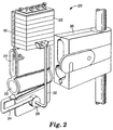
- FIG. 2 illustrates an embodiment of the circuit, here designated 20, which includes, starting from the top, a venous/cardiotomy blood reservoir 22, blood oxygenator 24, blood heat exchanger 26 and centrifugal blood pump 28, along with a vent line 30 venting the oxygenator 24 to the top of the reservoir 22.
- the oxygenator gas regulating mechanisms described in U.S. Patent No. 5,152,964 and European Patent Publication No. EP 0 591 896 may be used in the circuit.
- a line (not shown) would be used to provide pressure feedback from the venous line (not shown) to the oxygenator gas regulating mechanism (not shown) to control the gas pressure in the oxygenator.
- Line 32 drains the venous/cardiotomy reservoir 22 into the centrifugal blood pump 28.
- the upstream end of the line 32 is connected with the outlet of the reservoir 22, which is located at or adjacent the bottom of the reservoir 22, and the downstream end of the line 32 is connected with the inlet of the centrifugal blood pump 28, which brings blood into the pump 28 along the axis of rotation of the pump impeller (not shown).
- Line 34 is connected an outlet along the periphery of the pump 28 and to the heat exchanger 26 to allow blood to be pumped into the heat exchanger 26.
- the outlet of the centrifugal pump 28 is positioned along the top of the pump 28, and extends along a horizontal tangent of the circumferential peripheral surface of the pump 28.
- FIG 2 also illustrates a reservoir 22 and integral blood oxygenator 24/heat exchanger 26, each of which are made according to a novel process of the invention.
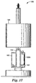
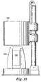
- the housings of these components are formed, as described below, by thermal forming thermoplastic sheets of material over heated vacuum molds, assembling the components, and providing a potting compound to seal the components while the assembly is spinning in a centrifuge/kiln apparatus illustrated in figures 16-18.
- a novel mounting bracket 36 which is adapted to closely receive the integral blood oxygenator 24/heat exchanger 26 to support the weight and hold the circuit 20 during the use of the circuit 20, and to support the housing of the integral blood oxygenator 24/heat exchanger 26 against internal pressure. It is contemplated that the housing of the integral blood oxygenator 24/heat exchanger 26 would be formed of resiliently flexible material, which while reasonably stiff, allows the walls of the housing to be flexed to vary oxygenator performance. Most preferably, the mounting bracket 36 includes means, such as a manually movable plate, for compressing the opposite walls of the housing of the oxygenator 24 toward one another to adjust oxygenation of blood flowing through the blood flow path of the oxygenator 24.
- the mounting bracket 36 preferably includes a mechanism for connecting the heat exchanger 26 with a conduit leading to a suitable source of heat exchanging fluid, such as water, and another conduit for drainage of the heat exchanging fluid.
- a suitable source of heat exchanging fluid such as water
- the mechanism may be of the type described in co-assigned U.S. Patent Nos. 4,846,177 and 5,255,734 (published after the priority date of the present application).
- the mechanism described in U.S. Patent No. 5,255,734 includes a valve that is opened only after the heat exchanger is sealingly held by the mechanism.
- the oxygenator fibers or mats have opposite ends which remain open until the oxygenator 24 and heat exchanger 26 are mounted in the mounting bracket 36, with the mounting bracket including mounting hardware and seals to provide a sealed gas path through the oxygenator fibers or mats.
- the arrangement is preferably such that oxygenator fibers or mats are sealed in one common action with the mechanism described for the heat exchanging fluid.
- seals may be brought into the appropriate sealing relationship with the oxygenator housing at the same time that the seals of the heat exchanging mounting mechanism described above are brought into sealing engagement with the heat exchanger 26.
- the heat exchanger may comprise a hollow fiber type heat exchanger, in which the fibers or mat have opposite open ends similar to the oxygenator fibers or mat.
- FIG 3 illustrates an embodiment of the invention, in which a novel integral oxygenator and heat exchanger, herein designated 40, is provided.
- the device 40 includes an oxygenator portion 42 and a heat exchanging portion 44 within a housing 46 formed by thermal forming two sheets of thermoplastic material and sealing (preferably heat sealing) the sheets together with rf energy.
- the device 40 does not include a reservoir, which would be supplied separately.
- the device 40 is adapted to be closely received in a mounting bracket 48 that is similar to mounting bracket 36 of figure 2.
- the device 40 includes a blood inlet 49 into the heat exchanging portion 44 along the bottom of the heat exchanging portion 44, and a blood outlet (not shown in figure 3) from the oxygenating portion 42 along or adjacent the top thereof, thus defining a blood flow path generally upwardly through the device.
- the device 40 is similar in most respects to the oxygenator 24/heat exchanger 26 of figure 2.
- Circuit 50 is similar in many respects to circuit 20.
- Circuit 50 may include, in addition to an oxygenating and heat exchanging device 52 similar to device 40 and oxygenator 24/heat exchanger 26 of figures 2 and 3, a reservoir 54, centrifugal blood pump 56, arterial blood filter 58 and hemo-concentrator 60.
- the oxygenating and heat exchanging device 52 of circuit 50 is turned ninety degrees relative to the oxygenator 24/heat exchanger 26 of circuit 20 so that the oxygenator and heat exchanging portions of the device 52 are arranged in side-by-side relationship. This orientation is believed to facilitate allowing the oxygenating and heat exchanging device 52 to function as bubble collection points.
- the reservoir 54 may take the form of the reservoir 12 or 22 of figures 1 or 2, or the reservoir 100 of figures 5-8.
- the reservoir 54 may take the form of any off-the-shelf reservoir that is commercially available, such as the one available under the trade designation "SARNSTM Integral Cardiotomy Reservoir” from Minnesota Mining and Manufacturing Company, St. Paul, Minnesota, U.S.A.
- the outlet of the centrifugal pump 56 extends generally upwardly so that the pump 56 can be gravity primed.
- the blood is then pumped via line 64 from the centrifugal pump 56 to the heat exchanging portion 66 of the oxygenating and heat exchanging device 52.
- the heat exchanging portion 66 is along the right side of the device 52 as shown in figure 4, with blood flow passing through the heat exchanging portion 66 and then through the oxygenating portion 68 from right to left in the figure, and finally exiting from adjacent the bottom of the left side of the oxygenating portion 68 into a line 70.
- Line 70 takes the blood to a conventional arterial blood filter 58 of the type commercially available, for example, from Gelman Sciences Inc., Ann Arbor, Michigan, U.S.A.
- the filtered blood travels via line 72 from the arterial blood filter 58 to a valve mechanism 74.
- the valve 74 allows the blood to be directed to a conventional hemo-concentrator 60 at the end of surgery to increase the hematocrit and decrease the fluid volume of the blood being reperfused into the patient.
- hematocrit is the percentage volume of blood occupied by cells.
- the blood is diluted with saline solution to increase blood volume without or with minimum donated blood.
- the extracorporeal support circuit may be primed with saline solution before the patient is supported by that circuit, with the saline prime diluting the patient's blood.
- a hemo-concentrator 60 may be provided to increase the hematocrit of the otherwise diluted blood.
- the valve 74 also allows blood to be reperfused directly to the patient during surgery, bypassing the hemo-concentrator 60.
- Figure 4 also shows a mounting bracket 76 similar in many respects to mounting brackets 36 and 48 of figures 2 and 3.
- the orientation of the supporting surfaces of mounting bracket 76, which support the oxygenating and heat exchanging device 52 is different to accommodate the different orientation of the oxygenating and heat exchanging device 52.
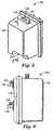
- FIGS 5-8 illustrate a integral venous/cardiotomy blood reservoir 100.
- the reservoir 100 comprises a housing 102 having walls defining two interior chambers 104 and 106 including a blood storage chamber 104 and a defoaming and filtering chamber 106. Each chamber 104 or 106 has a top and a bottom.
- the blood storage chamber 104 and defoaming and filtering chamber 106 are separated from one another by a generally vertical dividing wall 108 formed of substantially liquid impervious material.
- the dividing wall 108 has a vent 110 generally adjacent the top of the defoaming and filtering chamber 106 communicating with the blood storage chamber 104, and a port 112 generally adjacent the bottom of the defoaming and filtering chamber 106 communicating with the blood storage chamber 104.
- the defoaming and filtering chamber 106 is the interior space defined by the dividing wall 108, a generally vertically extending exterior wall 114 and the side and top and bottom walls extending between the exterior wall 114 and the
- At least one, preferably four, cardiotomy blood inlets 116 communicate with the defoaming and filtering chamber 106 for supplying scavenged blood to the reservoir 100, and at least one venous blood inlet 118 communicates with the defoaming and filtering chamber 106.
- the cardiotomy blood inlets 116 are positioned on the exterior wall 114 generally adjacent the top of the defoaming and filtering chamber 106, and the venous blood inlet 118 is positioned on the exterior wall 114 generally adjacent the bottom of the defoaming and filtering chamber 106.
- a blood outlet 120 is provided at/adjacent the bottom of the blood storage chamber 104 to allow drainage to blood stored in the blood storage chamber 104 to a blood pump, such as any suitable conventional positive-displacement roller pump or centrifugal blood pump.
- a blood filtering medium 122 is provided in the defoaming and filtering chamber 106 for filtering the blood to remove clots and other undesired matter from the blood.
- the blood filtering medium 122 is positioned in the defoaming and filtering chamber 106 such that blood entering the defoaming and filtering chamber 106 from the cardiotomy blood inlets 116 must pass through the blood filtering medium 122, but such that blood entering the defoaming and filtering chamber 106 through the venous inlet 118 does not pass through the blood filtering medium 122.
- the blood filtering medium 122 may comprise, for example, a pleated composite structure of two layers of extruded polyethylene with a layer of polyester filter material sandwiched between the polyethylene layers, such as available from several manufacturers including Tetko Inc., Briarcliff, New York, U.S.A.
- Tetko Inc. Briarcliff, New York, U.S.A.
- the periphery of the blood filtering medium 122 is sealed to the reservoir walls to ensure that blood entering through the cardiotomy inlets 116 passes through the filtering medium 122.
- a blood defoaming medium 124 is also provided, with the blood defoaming medium 124 taking up substantially the entire space of the defoaming and filtering chamber 106 not occupied by the filtering medium 122 such that blood entering the defoaming and filtering chamber 106 through the cardiotomy blood inlets 116 and venous blood inlet 118 must pass through the blood defoaming medium 124 before exiting the defoaming and filtering chamber 106 through the port 112.
- the blood defoaming medium 124 may comprise, for example, a conventional open cell polyurethane foam having approximately 20 pores per inch, with high molecular weight silicone solution added to the foam as is conventional. Most preferably three layers of such foam material are used, with one section 124A of such foam being placed between the filtering medium 122 and the cardiotomy inlets 116.
- the feature of the blood defoaming medium 124 and filtering medium 122 taking up substantially the entire space between the walls forming the defoaming and filtering chamber 106 is believed to improve the defoaming action of the reservoir 100.
- conventional luer type connection ports 126 and 128 are provided generally adjacent the cardiotomy inlets 116 and venous inlet 118.
- a luer type port 130 for a vacuum line (not shown), a tube connection post 132 for an overflow line (not shown) and a pressure/vacuum control valve 134. These features facilitate use of the reservoir 100 as a post surgical chest drainage container.
- the walls of the reservoir 100 are formed by thermal forming of thermoplastic material and sealing the walls together along peripheral portions thereof to form the chambers 104 and 106.
- the thermoplastic material is polyethyleneterephthalate ("PETE") sheets having a thickness of approximately 0.030-0.060 inches (0.76-1.52mm).
- the reservoir 100 may be formed with volume markings (not shown) including a marking designating the minimum desired operating level.
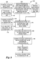
- FIG 9 is a flow chart illustrating the manufacturing process 150 for making the reservoir 100.
- the process includes steps 152 and 154 of thermal forming the sheets of thermoplastic (preferably PETE) material on the aluminum molds 154 and 156 shown in figures 10A and 10B to form the back and front panels of the reservoir 100.
- Initial cutting of the sheets may be done during the thermal forming steps. For example, openings for inlets and outlets may be cut while the formed sheets are on the thermal forming molds 154 and 156.
- the molds are designed to form sheets having various features relating to further processing of the reservoir 100. These include forming a potting "boat" on the boat-forming features 158 and 160 of the molds 154 and 156 adjacent the top of the back and front sheets, with the resulting potting boat (not shown) facilitating adding and distributing potting compound in a further processing step.
- the resulting potting boat will have a generally wide, V-shaped bottom corresponding to the bottom of the boat-forming features 158 and 160, with the bottom sloping gently upward from its center to opposite potting channels formed on channel-forming features 162 and 164 along opposite sides of the molds 154 and 156. This sloped V-shaped bottom of the boat facilitates even distribution of the potting compound to the potting channels when potting compound is later added.
- overflow reservoirs (not shown) formed on the overflow-forming features 166 and 168 of the molds 154 and 156.
- the resulting overflow reservoirs include inlets for potting compound that are positioned inwardly from the sides of the reservoir to gauge the depth of potting compound along each side of the reservoir 100 so that potting compound does not reach the overflow reservoirs until the depth of compound reaches the inlets.
- the process 150 also includes the initial step 170 of pleating and cutting material to form the blood filtering medium 122. Such pleating may be done in a continuous fashion on roll stock on what is known as a conventional "Grabowski" pleater.
- Initial step 172 refers to adding conventional defoaming solution to the foam layers and sections 124 and 124A.
- Initial step 174 is cutting a sheet of thermoplastic material (preferably PETE) to form the dividing wall 108 with a vent 110 and port 112.
- Step 176 is to place the section 124A of foam into the cardiotomy portion of the back panel, and seal the periphery of the pleated and cut blood filtering medium 122 to the back panel so as to hold the foam section 124 between the filtering medium 122 and the cardiotomy inlets 116.
- This partially assembled subassembly is then assembled in step 178 with the other sections of foam 124, the dividing wall 108 and the front panel.
- Step 180 is heat sealing along the periphery of the front and back panels and dividing walls together to form the reservoir 100, as well as heat sealing some additional features.
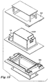
- Figures 11 and 12 show two halves 182 and 184 of an "rf" heat sealing fixture which may be used in step 180.
- the "rf" heating fixture 182 and 184 includes various rf heat sealing bars arranged in such a manner as to seal the front and back panels with the dividing wall 108 between them, while also sealing the panels so as to further form the potting boat, potting channels and potting overflow reservoirs.
- rf heat sealing bars 186 and 188 are positioned to form a heat seal between the potting boat and the top of the reservoir 100A (figure 13), and three rf heat sealing bars (at 190 and 192) are arranged to form a heat seal around the overflow inlets and overflow reservoirs.
- Reservoir 100A refers to the assembled reservoir components, with the front and back panels and dividing wall heat sealed together.
- Step 186 is to place the heat sealed assembly into a centrifuge/kiln 188 shown in figures 16-18, and add potting compound (preferably urethane resin) while spinning the assembled reservoir 100A.
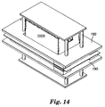
- Figures 13 and 14 illustrate preferred pressure plates 190 and 192 which hold the assembled, sealed reservoir 100A in the jaws of a vice 194 shown in figure 15-18, with the potting boat 196 (figure 13) facing upwardly and the overflow reservoirs (not shown) generally adjacent the bottom.
- the centrifuge/kiln 188 includes a hood 198 which contains the vice 194 and assembled reservoir 100A for heating and spinning the reservoir 100A.
- An opening 199 is provided in the hood 198 to allow potting compound to be added to the reservoir 100A while the reservoir 100A is spinning at a controlled, high temperature (preferably about 150°F (65°C)).
- FIGs 19-24 illustrate various aspects of another embodiment of the reservoir, here designated 200.
- Reservoir 200 includes many features similar in some respects to those shown in U.S. Patent Nos. 5,149,318 and 5,254,080, as well as co-pending U.S. patent application Serial No. 08/077,344, filed June 14, 1993, on "Quick-Changeover Blood Handling Apparatus", by Erin J. Lindsay.
- Reservoir 200 is similar in most respects to reservoir 100, particularly with respect to the internal structure of the reservoirs.
- reservoir 200 has two tracks or track means 202 and 204 each for slidably receiving its respective connector or other block 206 or 208.
- the arrangement is such as to facilitate conversion of the reservoir 200 from its use as a venous/cardiotomy reservoir, to a use after surgery collecting blood drained from the chest cavity.
- Figures 19-21 show features relating to use of the reservoir 200 during surgery.
- Connector block 206 may be referred to as a cardiotomy connector block 206, and it includes a plurality, preferably four, cardiotomy inlets connection posts 210 that are brought into sealed fluid communication with inlet bores 212 (figure 19) when the cardiotomy connector block 206 is fully inserted into track 202 (figure 20).
- Connector block 208 may be referred to as a venous connector block 208, and it includes at least one venous inlet connection post 214 that is brought into sealed fluid communication with the inlet bore 216 (figure 19) when the venous connector block 208 is fully inserted into track 204 (figure 20).
- connector blocks 206 and 208 Further details of the connector blocks 206 and 208 are shown in figures 21 and 22, including O-ring seal receiving channels 218, 219, 220, 221 and 222 which receive O-ring seals (not shown) to seal around the interface between the connector blocks 206 and 208 and the base defined between the rails of the tracks 202 and 204.
- Figures 23 and 24 show the reservoir 200 converted for use after surgery for use in collecting blood drained from the chest cavity. This conversion is performed simply by removing blocks 206 and 208 from tracks 202 and 204, and inserting drainage connector block 224 and closed block 226.
- the closed block 226 does not have any connection posts or features because it is intended merely to seal the venous inlets and other inlets into the lower portion of the blood filtering and defoaming chamber (similar to chamber 106).
- One or more O-rings may optionally be provided on the closed block 226 for sealing the venous inlets and other lower inlets/ports.
- the drainage connector block 224 includes a plurality, preferably three, of connection posts 228 for connecting a plurality of chest drainage lines to the cardiotomy inlets 212, and a connection post 230 for connecting an overflow line 232 to an overflow connection post 234 on the top of the blood storage chamber (similar to chamber 104).
- the overflow line 232 allows viewing blood drawn into the overflow line if/when the filtering medium becomes clogged, and for equalizing vacuum between the defoaming and filtering chamber and the blood storage chamber.
- a luer type port 236 similar to port 130 in figure 5
- a vacuum line not shown
- a pressure/vacuum control valve 238 similar to valve 134 in figure 5).
- the connector blocks 206, 208 and 224 allow the various tubing lines to be pre-packaged connected to the connector blocks 206, 208 and 224 to allow these connections to be made simply be fully inserting the appropriate connector blocks 206, 208 and/or 224 in the tracks 202 and 204.
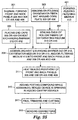
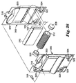
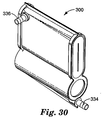
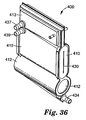
- Figures 25-37 illustrate various aspects of two different embodiments of the oxygenating and heat exchanging device of the invention, designated 300 in figures 25-30 and 400 in figures 31-37, including a novel process for manufacturing the oxygenating and heat exchanging devices 300 and 400 illustrated in part in the flow chart of figure 25.
- the oxygenating and heat exchanging device 300 is similar to oxygenating and heat exchanging devices 40 and 52 of figures 3 and 4, as well as the device shown at 24 and 26 of figure 2.
- the device 300 includes an oxygenating portion 302 and a heat exchanging portion 304 but does not include an arterial blood filtering section.
- the device 400 of figures 31-37 shows, in addition to an oxygenating portion 402 and heat exchanging portion 404, an arterial blood filtering section 405.
- Figures 28 and 33 show a front panel 306 or 406 and a back panel 308 or 408. Assembled between the front and back panels 306 or 406 and 308 or 408 are a hollow fiber type blood oxygenating medium 310 or 410, which may be of conventional design such as generally described in U.S. Patent No. 4,940,617; and an undulating, tubular metal heat exchanging barrier 312 or 412, which may be of the type described in U.S. Patent Nos. 4,846,177 and 5,255,734 (published after the priority date of the present application).
- Figure 33 also shows a pleated arterial blood filtering medium 413, which is a similar material to the blood filtering medium 122 shown in the reservoir 100 of figure 7.
- Step 401 in figure 25 is pleating the filtering medium 413.
- Step 309 is assembling the various components, e.g., heat exchanging barrier 312 or 412, oxygenating medium 310 or 410, filtering medium vinyl cap 332 or 432, and/or filtering medium 413 between the front and back panels 306 and 308 or 406 and 408.
- Figures 26 and 31 show aluminum molds 314 or 414 and 316 or 416 for thermal forming the front and back panels 306 and 308 or 406 and 408 (step 301), with the resulting panels shown in figures 27 and 32.
- the resulting front and back panels 306 and 308 or 406 and 408 include some features similar to those described above with respect to the blood reservoir 100.
- a potting boat 318 or 418 having a generally V-shaped bottom sloping gently upwardly from its center and extending outwardly into opposite downwardly-extending potting channels 320 and 420.
- the potting boats 318 and 418 are open along their tops to facilitate pouring potting compound (preferably urethane resin) into the boats 318 or 418, with the V-shaped bottom facilitating even distribution of the potting compound into the potting channels 320 or 420. See, e.g., step 315 which follows step 311 of heat sealing the periphery of the front and back panels 306 and 308 or 406 and 408.
- overflow reservoirs 322 or 422 for receiving excess potting compound.
- the overflow reservoirs 322 or 422 include inlets 324 or 424 which have a configuration extending generally radially inwardly relative to the axis of rotation of the assembled but unfinished devices 300 or 400 in the centrifuge/kiln (not shown but similar to centrifuge/kiln 188).
- the arrangement is such that the overflow-reservoir inlets 324 or 424 allow the potting compound to reach a specific depth along the opposite sides of the devices 300 or 400.
- the depth of potting compound 326 or 426 illustrated in figures 29, 34 and 35.
- Figure 35 illustrates that the actual depth of the potting compound 426 is generally along a parabolic curve (also 426), and the components may be positioned to account for this curve.
- Figures 28 and 33 show additional features relating to the process for making the devices 300 or 400.
- polyethylene end caps 328 or 428 are used to plug the opposite ends of the heat exchanging barrier 312 or 412 to prevent entry of potting compound into the internal space of the barrier 312 or 412 (see step 305 of figure 25).
- These caps 328 or 428 are removed or cut off after the potting compound has cured, preferably cut off in one integral operation with a step 317 of cutting the opposite sides of the devices 300 and 400 to expose the water path of the heat exchanger portion and the gas path of the oxygenating portion.
- the arrangement may be such that only the cap 328 or 428 at one end of the barrier 312 or 412 is cut off or removed, leaving the other end sealed.
- the filtering medium 413 of device 400 is positioned to avoid cutting the filtering medium 413 when cutting the opposite ends of the oxygenator fibers and the caps 428 in step 317.
- an internal thin-plastic water baffle (not shown) may be provided inside the heat exchanging barrier 312 or 412. Such a baffle is forced into position by water pressure.
- the ends of the hollow fibers of the oxygenating medium 310 or 410 are also sealed in step 307 before the step 315 of introducing potting compound into the assembled devices 300 or 400.
- the hollow fibers may be wound around a core plate 330 or 430 (step 303), with the plate 330 or 430 being internal to the final plane cuts through the potting compound.
- the final plane cuts expose the internal lumens of the hollow fibers to allow gas passage therethrough.
- the arrangement is similar with respect to embodiments having a hollow fiber type heat exchanger (not shown).
- a vinyl cap 332 or 432 is provided to seal the blood inlet into the heat exchanging portion of the device 300 or 400 to prevent the ingress of potting compound, thereby providing an inlet opening through the potting compound.
- a tubing connection post 334 or 434 (figures 30 and 36) is then mounted on the inlet opening.
- a blood outlet connection post 336 is mounted adjacent the top of the oxygenating portion of device 300, with blood traveling generally upwardly through the housing consecutively through the heat exchanging and blood oxygenating portions of the device 300.
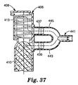
- a blood outlet post 437 is mounted adjacent the top of the filtering portion of the device 400, with blood traveling generally upwardly through the housing consecutively through the heat exchanging, blood oxygenating and blood filtering portions from the inlet connection post 434 to the outlet tubing connection post 437.
- a filter bypass connection post 439 is mounted adjacent the top of the blood oxygenating portion.
- a branched outlet tube 441 (figure 37) includes a bypass leg 443 connected to post 439 and a normal outlet leg 445 connected to post 437. In normal operation, the bypass leg 443 is clamped off, and blood passes from the filtering portion through the normal outlet leg 443. If the filtering medium 413 becomes clogged, the bypass leg 443 is unclamped to allow blood to bypass the filtering medium 413.
- the step 319 is to bond the various connectors described above to the housing of the device 300 or 400.
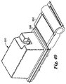
- FIGS 38-40 illustrate various aspects of one way of interconnecting the reservoir, herein designated 500 and the blood oxygenating and heat exchanging device, here designated 502.
- the top of the blood oxygenating and heat exchanging device 502 may be provide with a generally T-shaped flange 504 and the bottom of the reservoir 500 may be provided with a corresponding inverted, generally T-shaped flange 506.
- the arrangement is such as to allow an elongate clip 508 to be used to lock the reservoir 500 and blood oxygenating and heat exchanging device 502 together.
- the clip 508 and T-shaped flanges 504 and 506 are preferably provided with sufficient resilience to provide a resilient locking action.
Landscapes
- Health & Medical Sciences (AREA)
- Heart & Thoracic Surgery (AREA)
- Engineering & Computer Science (AREA)
- General Health & Medical Sciences (AREA)
- Veterinary Medicine (AREA)
- Anesthesiology (AREA)
- Biomedical Technology (AREA)
- Hematology (AREA)
- Life Sciences & Earth Sciences (AREA)
- Animal Behavior & Ethology (AREA)
- Public Health (AREA)
- Cardiology (AREA)
- Vascular Medicine (AREA)
- Urology & Nephrology (AREA)
- Mechanical Engineering (AREA)
- Emergency Medicine (AREA)
- Pulmonology (AREA)
- Chemical & Material Sciences (AREA)
- Chemical Kinetics & Catalysis (AREA)
- External Artificial Organs (AREA)
Claims (14)
- Integrale Blutoxygenations- und Wärmeaustauschvorrichtung (24; 26; 40; 52; 300; 400; 502) zum Oxygenieren von Blut und Erwärmen oder Abkühlen von Blut, wobei die Vorrichtung geeignet ist, im Betrieb mit einem Anordnungsgerät verbunden zu werden, das eine Quelle für sauerstoffreiches Gas und Wärmeaustauschfluid in Fluidkommunikation mit der Vorrichtung bringt und das eine Anordnungsklammer (36; 48; 76) zum lösbaren Aufnehmen und Halten der Vorrichtung aufweist, wobei die Vorrichtung aufweist:ein Trennmedium (310; 410) mit Hohlfasern zum Trennen von Blut und Gas, während es die Übertragung von Sauerstoff und Kohlendioxid über das Medium (310; 410) zuläßt, um das Blut zu oxygenieren, wobei das Trennmedium (310; 410) in einer Anordnung mit entgegengesetzten Enden angeordnet ist, wobei die Hohlfasern Innenlumen mit offenen Enden haben, die an den entgegengesetzten Enden des Trennmediums offen sind, so daß Gas die Lumen der Hohlfasern durchfließen kann;eine Wärmeaustauschsperre (312; 412) zum Trennen von Blut und einem Wärmeaustauschfluid, während sie die Wärmeübertragung über die Sperre (312; 412) zuläßt, um das Blut zu erwärmen oder abzukühlen, wobei die Sperre (312; 412) entgegengesetzte Enden hat, die allgemein benachbart und allgemein ausgerichtet zu den entgegengesetzten Enden des Trennmediums (310; 410) positioniert sind, und die Wärmeaustauschsperre mindestens ein Innenlumen mit offenen Enden hat, die an den entgegengesetzten Enden der Wärmeaustauschsperre offen sind;ein Gehäuse (46; 306; 308; 406; 408), das das Trennmedium (310; 410) und die Wärmeaustauschsperre (312; 412) hält, wobei das Gehäuse (46; 306; 308; 406; 408) in eine Konfiguration geformt ist, die dem Trennmedium (310; 410) und der Wärmeaustauschsperre (312; 412) entspricht, ohne die offenen Enden der Lumen der Hohlfasern des Trennmediums und die offenen Enden des Lumens der Wärmeaustauschsperre einzuschließen; undVergußmasse (326; 426), die das Gehäuse (46; 306; 308; 406; 408) benachbart zu den Enden des Trennmediums (310; 410) und der Wärmeaustauschsperre (312; 412) versiegelt, ohne die offenen Enden der Lumen der Hohlfasern des Trennmediums und die offenen Enden des Lumens der Wärmeaustauschsperre zu verschließen;einen Bluteinlaß (334; 434) und -auslaß (336; 437, 439) in das Gehäuse (46; 306; 308; 406; 408), die einen Blutfließweg innerhalb des Gehäuses über das Trennmedium (310; 410) außerhalb der Hohlfasern und entlang der Außenseite der Wärmeaustauschsperre (312; 412) bilden; undwobei sich die offenen Enden der Lumen der Hohlfasern und die offenen Enden des Lumens der Wärmeaustauschsperre in die Umgebung außerhalb des Gehäuses öffnen, damit sie in direkte Fluidkommunikation mit dem Anordnungsgerät gebracht werden können.
- Vorrichtung nach Anspruch 1, wobei das Gehäuse (46; 306; 308; 406; 408) entgegengesetzte Wände (306; 308; 406; 408) entlang von entgegengesetzten Seiten des Trennmediums (310; 410) aufweist, wobei der Blutfließweg zwischen den entgegengesetzten Wänden (306; 308; 406; 408) des Gehäuses (46; 306; 308; 406; 408) entlang der Außenseite der Hohlfasern des Trennmediums (310; 410) gebildet ist und die entgegengesetzten Wände (306; 308; 406; 408) innerhalb eines Biegebereichs elastisch flexibel sind, damit die entgegengesetzten Wände (306; 308; 406; 408) zusammengedrückt werden können, um die Oxygenation von Blut einzustellen, das durch den Blutfließweg fließt.
- Kombination aus einer integralen Blutoxygenations- und Wärmeaustauschvorrichtung nach Anspruch 1 mit einem Anordnungsgerät, das eine Quelle für sauerstoffreiches Gas und Wärmeaustauschfluid in Fluidkommunikation mit der Vorrichtung bringt;wobei das Anordnungsgerät aufweist:eine Anordnungsklammer (36; 48; 76) zum lösbaren Aufnehmen und Halten der Vorrichtung (24; 26; 40; 52; 300; 400; 502), wobei die Anordnungsklammer (36; 48; 76) so konfiguriert ist, daß sie die Vorrichtung (24; 26; 40; 52; 300; 400; 502) eng aufnimmt, um das Gewicht der Vorrichtung (24; 26; 40; 52; 300; 400; 502) zu tragen und das Gehäuse der Vorrichtung gegen Innendruck im Gehäuse (46; 306; 308; 406; 408) zu unterstützen;eine Einrichtung in der Anordnungsklammer (36; 48; 76) zum Eingriff mit der Vorrichtung (24; 26; 40; 52; 300; 400; 502), um eine Abdichtung mit der Vorrichtung (24; 26; 40; 52; 300; 400; 502) benachbart zu den offenen Enden der Lumen der Hohlfasern des Trennmediums (310; 410) zu bilden und die Lumen der Hohlfasern in Fluidkommunikation mit einer Quelle für sauerstoffreiches Gas zu bringen; undeine Einrichtung in der Anordnungsklammer (36; 48; 76) zum Eingriff mit der Vorrichtung (24; 26; 40; 52; 300; 400; 502), um eine Abdichtung mit der Vorrichtung benachbart zu den offenen Enden des Lumens der Wärmeaustauschsperre (312; 412) zu bilden und das Lumen der Wärmeaustauschsperre (312; 412) in Fluidkommunikation mit einer Quelle für Wärmeaustauschfluid zu bringen.
- Kombination nach Anspruch 3, wobei:das Gehäuse (46; 306; 308; 406; 408) der Vorrichtung (24; 26; 40; 52; 300; 400; 502) entgegengesetzte Wände (306; 308; 406; 408) entlang von entgegengesetzten Seiten des Trennmediums (310; 410) aufweist, wobei der Blutfließweg zwischen den entgegengesetzten Wänden (306; 308; 406; 408) des Gehäuses (46; 306; 308; 406; 408) entlang einer Oberfläche des Trennmediums (310; 410) gebildet ist und die entgegengesetzten Wände (306; 308; 406; 408) innerhalb eines Biegebereichs elastisch flexibei sind, damit die entgegengesetzten Wände (306; 308; 406; 408) zusammengedrückt werden können, um die Oxygenation von Blut einzustellen, das durch den Blutfließweg fließt; unddas Gerät ferner eine Einrichtung in der Anordnungsklammer (36; 48; 76) zum Zusammendrücken der entgegengesetzten Wände (306; 308; 406; 408) des Gehäuses (46; 306; 308; 406; 408) aufweist, um die Oxygenation von Blut einzustellen, das durch den Blutfließweg fließt.
- Verfahren zur Bildung einer integralen Blutoxygenations- und Wärmeaustauschvorrichtung, die geeignet ist, im Betrieb mit einem Anordnungsgerät verbunden zu werden, das eine Quelle für sauerstoffreiches Gas und Wärmeaustauschfluid in Fluidkommunikation mit der Vorrichtung bringt und das eine Anordnungsklammer zum lösbaren Aufnehmen und Halten dieser Vorrichtung aufweist, wobei das Verfahren die folgenden Schritte aufweist:(a) Bereitstellen eines Hohlfasern aufweisenden Trennmediums (310; 410) zum Trennen von Blut und Gas voneinander, während die Sauerstoff- und Kohlendioxidübertragung über das Trennmedium (310; 410) erfolgen kann, wobei das Trennmedium (310; 410) entgegengesetzte Enden hat;(b) Bereitstellen einer Wärmeaustauschsperre (312; 412) zum Trennen von Blut und Wärmeaustauschfluid voneinander, während die Wärmeübertragung dazwischen über die Wärmeaustauschsperre (312; 412) erfolgen kann, wobei die Wärmeaustauschsperre (312; 412) entgegengesetzte Enden und mindestens ein Innenlumen mit offenen Enden hat, die an den entgegengesetzten Enden der Wärmeaustauschsperre offen sind;(c) Warmformen mindestens einer Bahn (306; 308; 406; 408) aus thermoplastischem Material, um ein Gehäuse in dem Trennmedium und der Wärmeaustauschsperre entsprechender Konfiguration zum Aufnehmen des Trennmediums (310; 410) und der Wärmeaustauschsperre (312; 412) zu bilden, wobei die entgegengesetzten Enden des Trennmediums (310; 410) und der Wärmeaustauschsperre (312; 412) allgemein benachbart und allgemein zueinander ausgerichtet sind und die Bahn (306; 308; 406; 408) auch einen Kanal (320; 420) zum Lenken von Vergußmasse (326; 426) benachbart zu den entgegengesetzten Enden des Trennmediums (310; 410) und der Wärmeaustauschsperre (312; 412) bildet; wobei die Bahn (306; 308; 406; 408) auch einen Bluteinlaß (334; 434) in das Gehäuse bildet und einen Blutauslaß (336; 437) hat, wobei der Bluteinlaß und -auslaß einen Blutfließweg innerhalb des Gehäuses über das Trennmedium (310; 410) außerhalb der Hohlfasern und entlang der Außenseite der Wärmeaustauschsperre (312; 412) bilden;(d) Plazieren des Trennmediums (310; 410) und der Wärmeaustauschsperre (312; 412) zwischen die das Gehäuse bildenden Bahnen (306; 308; 406; 408);(e) Wärmeversiegeln der Bahnen (306; 308; 406; 408) miteinander, um eine das Gehäuse, das Trennmedium (310; 410) und die Wärmeaustauschsperre (312; 412) aufweisende Anordnung zu bilden;(f) Plazieren der Anordnung in einer Zentrifuge (188);(g) Schleudern der Anordnung in der Zentrifuge (188), wobei die entgegengesetzten Enden des Trennmediums (310; 410) und der Wärmeaustauschsperre (312; 412) entlang von entgegengesetzten Seiten der Drehachse liegen;(h) Gießen von ungehärteter Vergußmasse in den Kanal (320; 420), während die Anordnung in der Zentrifuge (188) schleudert;(i) fortgesetztes Schleudern der Anordnung in der Zentrifuge (188) bis nach Erstarren der Vergußmasse;(j) Schneiden der Bahnen (306; 308; 406; 408) und der gehärteten Vergußmasse, um die entgegengesetzten Enden des Trennmediums (310; 410) und der Wärmeaustauschsperre (312; 412) zur Umgebung außerhalb des Gehäuses freizulegen; und(k) Offenlassen der entgegengesetzten Enden des Trennmediums (310; 410) und der Wärmeaustauschsperre (312; 412) zur Umgebung außerhalb des Gehäuses.
- Verfahren nach Anspruch 5, ferner mit den folgenden Schritten: Bereitstellen eines die Zentrifuge(188) umgebenden Ofens (188); undwährend der Schritte (g), (h) und (i) erfolgendes Erwärmen der Anordnung im Ofen (188), während die Schleuder (188) die Anordnung schleudert, bis die Vergußmasse (326; 426) gehärtet ist.
- Extrakorporaler Kreislaufunterstützungskreislauf zum Unterstützen eines Patienten bei einem kardiopulmonalen Bypass, wobei der Kreislauf aufweist:ein Blutreservoir (22; 54; 100; 200; 500) mit einer Entschäumungs-und Filterkammer (106) und einer Blutspeicherkammer (104) in Fluidkommunikation mit der Entschäumungs- und Filterkammer (106), wobei das Reservoir mindestens einen Kardiotomiebluteinlaß (116; 210) und mindestens einen venösen Bluteinlaß (118; 214) in die Entschäumungs- und Filterkammer (106) sowie einen Auslaß (120) zum Ablassen der Blutspeicherkammer (104) hat, wobei die Entschäumungs- und Filterkammer (106) ein Entschäumungsmedium (124) und Filtermedium (122) aufweist; undeine integrale Blutoxygenations- und Wärmeaustauschvorrichtung (24; 26; 40; 52; 300; 400; 502) zum Oxygenieren von Blut und Erwärmen oder Abkühlen von Blut, wobei die Vorrichtung geeignet ist, im Betrieb mit einem Anordnungsgerät verbunden zu werden, das eine Quelle für sauerstoffreiches Gas und Wärmeaustauschfluid in Fluidkommunikation mit der Vorrichtung bringt und das eine Anordnungsklammer (36; 48; 76) zum lösbaren Aufnehmen und Halten der Vorrichtung aufweist, wobei die Vorrichtung aufweist:ein Hohlfasern aufweisendes Trennmedium (310; 410) zum Trennen von Blut und Gas, während es die Übertragung von Sauerstoff und Kohlendioxid über das Medium (310; 410) zuläßt, um das Blut zu oxygenieren, wobei das Trennmedium (310; 410) in einer Anordnung mit entgegengesetzten Enden angeordnet ist und die Hohlfasern Innenlumen mit offenen Enden haben, die an den entgegengesetzten Enden des Trennmediums offen sind, so daß Gas die Lumen der Hohlfasern durchfließen kann;eine Wärmeaustauschsperre (312; 412) zum Trennen von Blut und einem Wärmeaustauschfluid, während sie die Wärmeübertragung über die Sperre (312; 412) zuläßt, um das Blut zu erwärmen oder abzukühlen, wobei die Sperre (312; 412) entgegengesetzte Enden hat, die allgemein benachbart und allgemein ausgerichtet zu den entgegengesetzten Enden des Trennmediums (310; 410) positioniert sind, und die Wärmeaustauschsperre (312; 412) mindestens ein Innenlumen mit offenen Enden hat, die an den entgegengesetzten Enden der Wärmeaustauschsperre (312; 412) offen sind;ein Gehäuse (46; 306; 308; 406; 408), das das Trennmedium (310; 410) und die Wärmeaustauschsperre (312; 412) hält, wobei das Gehäuse (46; 306; 308; 406; 408) in eine dem Trennmedium (310; 410) und der Wärmeaustauschsperre (312; 412) entsprechende Konfiguration geformt ist, ohne die offenen Enden der Lumen der Hohlfasern des Trennmediums (310; 410) und die offenen Enden des Lumens der Wärmeaustauschsperre (312; 412) einzuschließen;Vergußmasse (326; 426), die das Gehäuse (46; 306; 308; 406; 408) benachbart zu den Enden des Trennmediums (310; 410) und der Wärmeaustauschsperre (312; 412) versiegelt, ohne die offenen Enden der Lumen der Hohlfasern des Trennmediums (310; 410) und die offenen Enden des Lumens der Wärmeaustauschsperre (312; 412) zu verschließen; undeinen Bluteinlaß (334; 434) und -auslaß (336; 437, 439) in den Abschnitt des Gehäuses (46; 306; 308; 406; 408), der das Trennmedium (310; 410) und die Wärmeaustauschsperre (312; 412) hält, wobei der Bluteinlaß (334; 434) und -auslaß (336; 437, 439) einen Blutfließweg innerhalb des Gehäuses (46; 306; 308; 406; 408) über das Trennmedium (310; 410) außerhalb der Hohlfasern und entlang der Außenseite der Wärmeaustauschsperre (312; 412) bilden; undwobei sich die offenen Enden der Lumen der Hohlfasern und die offenen Enden des Lumens der Wärmeaustauschsperre (312; 412) direkt in die Umgebung außerhalb des Gehäuses (46; 306; 308; 406; 408) öffnen, damit sie in direkte Fluidkommunikation mit dem Anordnungsgerät gebracht werden können;wobei der Bluteinlaß der Vorrichtung in Fluidkommunikation mit dem Blutauslaß (120) des Reservoirs (22; 54; 100; 200; 500) steht.
- Kreislauf nach Anspruch 7, ferner mit einer Blutleitung (32; 34; 62; 64), die den Auslaß des Reservoirs (22; 54) in Fluidkommunikation mit dem Bluteinlaß der Vorrichtung (52) bringt, wobei die Blutleitung (62; 64) zum Pumpen des Bluts durch die Blutleitung (62; 64) aus dem Reservoir (22; 54) in das Gehäuse der Vorrichtung (52) geeignet ist.
- Kreislauf nach Anspruch 8, ferner mit einer Zentrifugalblutpumpe (28; 56), die entlang der Blutleitung (32; 34; 62; 64) angeordnet ist, um Blut aus dem Reservoir (22; 54) durch die Vorrichtung (24; 26; 52) zu pumpen;wobei das Gehäuse der Vorrichtung (22; 54) aus mindestens einer Bahn aus thermoplastischem Material in eine Konfiguration warmgeformt ist, die dem Trennmedium (310; 410) und der Wärmeaustauschsperre (312; 412) entspricht, ohne die offenen Enden der Lumen der Hohlfasern des Trennmediums (310; 410) und die offenen Enden des Lumens der Wärmeaustauschsperre (312; 412) einzuschließen, und die das Gehäuse bildende Bahn aus thermoplastischem Material auch einen Abschnitt aufweist, der die Zentrifugalblutpumpe hält.
- Kreislauf nach Anspruch 9, wobei die Zentrifugalblutpumpe (28) lösbar an der Bahn aus thermoplastischem Material gehalten wird.
- Kreislauf nach Anspruch 8, wobei die Blutleitung aus elastisch flexiblem Schlauchmaterial gebildet ist, das geeignet ist, in eine Verdrängerrollenpumpe plaziert zu werden, um Blut aus dem Reservoir (22; 54) durch das Gehäuse der Vorrichtung (24; 26; 52) zu pumpen.
- Kreislauf nach Anspruch 7, wobei das Gehäuse (46; 306; 308; 406; 408) der Vorrichtung entgegengesetzte Wände (306; 308; 406; 408) entlang von entgegengesetzten Seiten des Trennmediums (310; 410) aufweist, wobei der Blutfließweg zwischen den entgegengesetzten Wänden (306; 308; 406; 408) des Gehäuses (46; 306; 308; 406; 408) entlang einer Oberfläche des Trennmediums (310; 410) gebildet ist und die entgegengesetzten Wände (306; 308; 406; 408) innerhalb eines Biegebereichs elastisch flexibel sind, damit die entgegengesetzten Wände (306; 308; 406; 408) zusammengedrückt werden können, um die Oxygenation von Blut einzustellen, das durch den Blutfließweg fließt.
- Kreislauf nach Anspruch 7, ferner mit einem Gerät, das eine Quelle für sauerstoffreiches Gas und Wärmeaustauschfluid in Fluidkommunikation mit der Vorrichtung bringt, wobei das Gerät aufweist:eine Anordnungsklammer (36; 48; 76) zum lösbaren Aufnehmen und Halten der Vorrichtung, wobei die Anordnungsklammer (36; 48; 76) so konfiguriert ist, daß sie das Gehäuse (46; 306; 308; 406; 408) der Vorrichtung (24; 26; 52) eng aufnimmt, um das Gewicht der Vorrichtung (24; 26; 52) zu tragen und das Gehäuse (46; 306; 308; 406; 408) der Vorrichtung (24; 26; 52) gegen Innendruck im Gehäuse (46; 306; 308; 406; 408) zu unterstützen;eine Einrichtung in der Anordnungsklammer (36; 48; 76) zum Eingriff mit der Vorrichtung, um eine Abdichtung mit der Vorrichtung benachbart zu den offenen Enden der Lumen der Hohlfasern des Trennmediums (310; 410) zu bilden und die Lumen der Hohlfasern in Fluidkommunikation mit einer Quelle für sauerstoffreiches Gas zu bringen; undeine Einrichtung in der Anordnungsklammer (36; 48; 76) zum Eingriff mit der Vorrichtung, um eine Abdichtung mit der Vorrichtung benachbart zu den offenen Enden des Lumens der Wärmeaustauschsperre (312; 412) zu bilden und das Lumen der Wärmeaustauschsperre (312; 412) in Fluidkommunikation mit einer Quelle für Wärmeaustauschfluid zu bringen.
- Kreislauf nach Anspruch 13, wobei:das Gehäuse (46; 306; 308; 406; 408) der Vorrichtung entgegengesetzte Wände (306; 308; 406; 408) entlang von entgegengesetzten Seiten des Trennmediums (310; 410) aufweist, wobei der Blutfließweg zwischen den entgegengesetzten Wänden (306; 308; 406; 408) des Gehäuses (46; 306; 308; 406; 408) entlang einer Oberfläche des Trennmediums (310; 410) gebildet ist und die entgegengesetzten Wände (306; 308; 406; 408) innerhalb eines Biegebereichs elastisch flexibel sind, damit die entgegengesetzten Wände (306; 308; 406; 408) zusammengedrückt werden können, um die Oxygenation von Blut einzustellen, das durch den Blutfließweg fließt; unddas Anordnungsgerät (36; 48; 76) ferner eine Einrichtung in der Anordnungsklammer (36; 48; 76) zum Zusammendrücken der entgegengesetzten Wände (306; 308; 406; 408) des Gehäuses (46; 306; 308; 406; 408) der Vorrichtung aufweist, um die Oxygenation von Blut einzustellen, das durch den Blutfließweg fließt.
Applications Claiming Priority (3)
| Application Number | Priority Date | Filing Date | Title |
|---|---|---|---|
| US08/142,809 US5514335A (en) | 1993-10-25 | 1993-10-25 | Blood oxygenation system and reservoir and method of manufacture |
| US142809 | 1993-10-25 | ||
| PCT/US1994/011664 WO1995011709A2 (en) | 1993-10-25 | 1994-10-21 | Blood oxygenation system and reservoir and method of manufacture |
Publications (2)
| Publication Number | Publication Date |
|---|---|
| EP0725657A1 EP0725657A1 (de) | 1996-08-14 |
| EP0725657B1 true EP0725657B1 (de) | 2000-02-09 |
Family
ID=22501369
Family Applications (1)
| Application Number | Title | Priority Date | Filing Date |
|---|---|---|---|
| EP94931845A Expired - Lifetime EP0725657B1 (de) | 1993-10-25 | 1994-10-21 | Blutsauerstoffsystem und herstellverfahren |
Country Status (7)
| Country | Link |
|---|---|
| US (3) | US5514335A (de) |
| EP (1) | EP0725657B1 (de) |
| JP (1) | JP3532568B2 (de) |
| CN (1) | CN1133566A (de) |
| CA (1) | CA2173854A1 (de) |
| DE (1) | DE69422997T2 (de) |
| WO (1) | WO1995011709A2 (de) |
Cited By (13)
| Publication number | Priority date | Publication date | Assignee | Title |
|---|---|---|---|---|
| US10722631B2 (en) | 2018-02-01 | 2020-07-28 | Shifamed Holdings, Llc | Intravascular blood pumps and methods of use and manufacture |
| US11185677B2 (en) | 2017-06-07 | 2021-11-30 | Shifamed Holdings, Llc | Intravascular fluid movement devices, systems, and methods of use |
| US11511103B2 (en) | 2017-11-13 | 2022-11-29 | Shifamed Holdings, Llc | Intravascular fluid movement devices, systems, and methods of use |
| US11654275B2 (en) | 2019-07-22 | 2023-05-23 | Shifamed Holdings, Llc | Intravascular blood pumps with struts and methods of use and manufacture |
| US11724089B2 (en) | 2019-09-25 | 2023-08-15 | Shifamed Holdings, Llc | Intravascular blood pump systems and methods of use and control thereof |
| US11964145B2 (en) | 2019-07-12 | 2024-04-23 | Shifamed Holdings, Llc | Intravascular blood pumps and methods of manufacture and use |
| US12102815B2 (en) | 2019-09-25 | 2024-10-01 | Shifamed Holdings, Llc | Catheter blood pumps and collapsible pump housings |
| US12121713B2 (en) | 2019-09-25 | 2024-10-22 | Shifamed Holdings, Llc | Catheter blood pumps and collapsible blood conduits |
| US12161857B2 (en) | 2018-07-31 | 2024-12-10 | Shifamed Holdings, Llc | Intravascular blood pumps and methods of use |
| US12220570B2 (en) | 2018-10-05 | 2025-02-11 | Shifamed Holdings, Llc | Intravascular blood pumps and methods of use |
| US12409310B2 (en) | 2019-12-11 | 2025-09-09 | Shifamed Holdings, Llc | Descending aorta and vena cava blood pumps |
| US12465748B2 (en) | 2019-08-07 | 2025-11-11 | Supira Medical, Inc. | Catheter blood pumps and collapsible pump housings |
| US12599758B2 (en) | 2019-12-19 | 2026-04-14 | Shifamed Holdings, Llc | Intravascular blood pumps, motors, and fluid control |
Families Citing this family (65)
| Publication number | Priority date | Publication date | Assignee | Title |
|---|---|---|---|---|
| US5514335A (en) * | 1993-10-25 | 1996-05-07 | Minnesota Mining And Manufacturing Company | Blood oxygenation system and reservoir and method of manufacture |
| DE19534502C2 (de) * | 1995-09-05 | 1997-10-09 | Helmdach Anke Dipl Produktdesi | Medizinische Anlage |
| JP3902232B2 (ja) * | 1995-11-30 | 2007-04-04 | テルモ カーディオバスキュラー システムズコーポレイション | 多層中空繊維本体およびその製法 |
| US5762868A (en) * | 1995-11-30 | 1998-06-09 | Minnesota Mining And Manufacturing Company | Blood oxygenator and heat exchanger |
| JP3256157B2 (ja) * | 1996-01-25 | 2002-02-12 | 天野 繁久 | 人工心肺装置 |
| US5770073A (en) * | 1996-03-15 | 1998-06-23 | Minntech Corporation | Combined cardiotomy and venous reservoir |
| US5871693A (en) * | 1996-06-07 | 1999-02-16 | Minnesota Mining And Manufacturing Company | Modular blood treatment cartridge |
| US6241945B1 (en) * | 1998-03-16 | 2001-06-05 | Life Science Holdings, Inc. | Modular combined pump, filtration, oxygenation and/or debubbler apparatus |
| US6113782A (en) * | 1998-07-28 | 2000-09-05 | Terumo Cardiovascular Systems Corporation | Potting of tubular bundles in housing |
| US6468473B1 (en) | 1999-02-10 | 2002-10-22 | Terumo Cardiovascular Systems Corporation | Self-contained pack assembly for an extracorporeal blood circuit |
| US6306346B1 (en) * | 1999-02-10 | 2001-10-23 | Terumo Cardiovascular Systems Corporation | Self-contained pack assembly for an extracorporeal blood circuit |
| US6508983B1 (en) | 1999-07-19 | 2003-01-21 | Cobe Cardiovascular | Exchanger apparatus and method of manufacture |
| US6613279B1 (en) | 1999-08-31 | 2003-09-02 | Medtronic, Inc. | Method and apparatus for improving blood mixing in oxygenators |
| US6464666B1 (en) * | 1999-10-08 | 2002-10-15 | Augustine Medical, Inc. | Intravenous fluid warming cassette with stiffening member and integral handle |
| WO2001082999A2 (en) * | 2000-04-27 | 2001-11-08 | Medtronic, Inc. | Cardiorespiratory system with improved biocompatible coating |
| US6773670B2 (en) | 2001-02-09 | 2004-08-10 | Cardiovention, Inc. C/O The Brenner Group, Inc. | Blood filter having a sensor for active gas removal and methods of use |
| US6730267B2 (en) | 2001-02-09 | 2004-05-04 | Cardiovention, Inc. | Integrated blood handling system having active gas removal system and methods of use |
| DE10147903C1 (de) * | 2001-09-28 | 2003-04-17 | Fresenius Medical Care De Gmbh | Membranvorrichtung für die Dialyse und/oder Filtration sowie Gehäusemantel einer derartigen Membranvorrichtung |
| USD484982S1 (en) | 2002-09-27 | 2004-01-06 | Baxter International Inc. | Chassis for a medical machine |
| USD492034S1 (en) | 2002-09-27 | 2004-06-22 | Baxter International Inc. | Base for a medical machine |
| USD483872S1 (en) | 2002-09-27 | 2003-12-16 | Baxter International Inc. | Display portion for a medical machine |
| US8182440B2 (en) * | 2002-09-27 | 2012-05-22 | Baxter International Inc. | Dialysis machine having combination display and handle |
| US7022099B2 (en) * | 2003-03-17 | 2006-04-04 | Cardiovention, Inc. | Extracorporeal blood handling system with automatic flow control and methods of use |
| EP1832303A1 (de) | 2004-11-24 | 2007-09-12 | LIFEBRIDGE Medizintechnik AG | Vorrichtung zur Bereitstellung eines extrakorporalen Blutkreislaufs |
| US7563248B2 (en) * | 2005-03-17 | 2009-07-21 | Smisson-Cartledge Biomedical Llc | Infusion fluid heat exchanger and cartridge |
| US8834399B2 (en) | 2010-12-07 | 2014-09-16 | Zoll Lifebridge Gmbh | Cardiopulmonary apparatus and methods for preserving organ viability |
| US8187214B2 (en) | 2006-10-30 | 2012-05-29 | Lifebridge Medizintechnik Ag | Apparatus for making extracorporeal blood circulation available |
| US9358331B2 (en) | 2007-09-13 | 2016-06-07 | Fresenius Medical Care Holdings, Inc. | Portable dialysis machine with improved reservoir heating system |
| EP3511034B1 (de) | 2007-11-29 | 2023-03-29 | Fresenius Medical Care Holdings, Inc. | System zur extrakorporalen blutbehandlung und durchführung von hämodialyse und hämofiltration |
| US9174791B2 (en) | 2007-12-11 | 2015-11-03 | Tokitae Llc | Temperature-stabilized storage systems |
| US9205969B2 (en) | 2007-12-11 | 2015-12-08 | Tokitae Llc | Temperature-stabilized storage systems |
| US8485387B2 (en) | 2008-05-13 | 2013-07-16 | Tokitae Llc | Storage container including multi-layer insulation composite material having bandgap material |
| US8069680B2 (en) | 2007-12-11 | 2011-12-06 | Tokitae Llc | Methods of manufacturing temperature-stabilized storage containers |
| US8215518B2 (en) * | 2007-12-11 | 2012-07-10 | Tokitae Llc | Temperature-stabilized storage containers with directed access |
| US8603598B2 (en) * | 2008-07-23 | 2013-12-10 | Tokitae Llc | Multi-layer insulation composite material having at least one thermally-reflective layer with through openings, storage container using the same, and related methods |
| US9139351B2 (en) | 2007-12-11 | 2015-09-22 | Tokitae Llc | Temperature-stabilized storage systems with flexible connectors |
| US8211516B2 (en) * | 2008-05-13 | 2012-07-03 | Tokitae Llc | Multi-layer insulation composite material including bandgap material, storage container using same, and related methods |
| US8887944B2 (en) | 2007-12-11 | 2014-11-18 | Tokitae Llc | Temperature-stabilized storage systems configured for storage and stabilization of modular units |
| US8215835B2 (en) * | 2007-12-11 | 2012-07-10 | Tokitae Llc | Temperature-stabilized medicinal storage systems |
| US9140476B2 (en) | 2007-12-11 | 2015-09-22 | Tokitae Llc | Temperature-controlled storage systems |
| US8377030B2 (en) * | 2007-12-11 | 2013-02-19 | Tokitae Llc | Temperature-stabilized storage containers for medicinals |
| US8545754B2 (en) | 2009-04-23 | 2013-10-01 | Medtronic, Inc. | Radial design oxygenator with heat exchanger |
| DE102010004600A1 (de) * | 2010-01-13 | 2011-07-14 | Marseille, Oliver, Dr.-Ing., 52066 | Anordnung mit einer Blutpumpe und einem Gasaustauscher zur extrakorporalen Membranoxygenierung |
| US9447995B2 (en) | 2010-02-08 | 2016-09-20 | Tokitac LLC | Temperature-stabilized storage systems with integral regulated cooling |
| US9372016B2 (en) | 2013-05-31 | 2016-06-21 | Tokitae Llc | Temperature-stabilized storage systems with regulated cooling |
| US8253389B2 (en) * | 2010-02-17 | 2012-08-28 | Texas Instruments Incorporated | Battery protection circuit and method for energy harvester circuit |
| US9318932B2 (en) | 2010-06-14 | 2016-04-19 | Black & Decker Inc. | Control unit for a power tool |
| IT1402590B1 (it) * | 2010-11-05 | 2013-09-13 | Rand Srl | Apparecchiatura medicale portatile per la assistenza cardiorespiratoria a pazienti |
| US10569002B2 (en) * | 2010-11-05 | 2020-02-25 | Rand S.R.L. | Portable medical apparatus for cardiopulmonary aid to patients |
| US8882693B2 (en) | 2010-12-07 | 2014-11-11 | Zoll Lifebridge Gmbh | Cardiopulmonary apparatus and methods for preserving life |
| CA2819792A1 (en) | 2010-12-07 | 2012-06-14 | Zoll Lifebridge Gmbh | Method and system for filling and venting a device for extracorporeal blood treatment, with stepped flooding of a filter |
| EP2731639B1 (de) | 2011-07-15 | 2018-01-24 | Cardiac Assist, Inc. | Vorrichtung zur kühlung oder erwärmungg der körpertemperatur eines patienten |
| US9450471B2 (en) | 2012-05-24 | 2016-09-20 | Milwaukee Electric Tool Corporation | Brushless DC motor power tool with combined PCB design |
| US9201036B2 (en) | 2012-12-21 | 2015-12-01 | Fresenius Medical Care Holdings, Inc. | Method and system of monitoring electrolyte levels and composition using capacitance or induction |
| US9157786B2 (en) * | 2012-12-24 | 2015-10-13 | Fresenius Medical Care Holdings, Inc. | Load suspension and weighing system for a dialysis machine reservoir |
| US9787159B2 (en) | 2013-06-06 | 2017-10-10 | Milwaukee Electric Tool Corporation | Brushless DC motor configuration for a power tool |
| US9630132B2 (en) * | 2014-07-01 | 2017-04-25 | Caterpillar Inc. | Fluid filtering system |
| ITUB20159389A1 (it) * | 2015-12-18 | 2017-06-18 | Eurosets Srl | Apparecchiatura per la decapneizzazione del sangue |
| WO2018026672A1 (en) * | 2016-08-01 | 2018-02-08 | Gipson Keith | System and method for reducing gaseous microemboli using venous blood bypass with filter |
| EP4706704A2 (de) | 2016-09-22 | 2026-03-11 | Michigan Critical Care Consultants, Inc. | Vorrichtungen und verfahren zur extrakorporalen aufbereitung von blut |
| LU100759B1 (de) | 2017-09-20 | 2019-07-17 | Hemovent Gmbh | Gas-Austausch-Einheit |
| CN111787964B (zh) * | 2018-02-26 | 2024-07-12 | 海沃恩有限公司 | 用于固持氧合器和血泵的固持装置 |
| US11541157B2 (en) | 2019-06-18 | 2023-01-03 | Michigan Critical Care Consultants, Inc. | Membrane oxygenator with gas exchange fiber lumen access based on fiber effective length |
| CN114342918B (zh) * | 2021-02-08 | 2023-01-17 | 苏州心擎医疗技术有限公司 | 温血器官转运平台及排气方法 |
| US11878097B2 (en) * | 2021-05-25 | 2024-01-23 | Arnold J. Lande | Vacuum assisted self-priming heart lung machine in a box |
Family Cites Families (77)
| Publication number | Priority date | Publication date | Assignee | Title |
|---|---|---|---|---|
| US3468631A (en) * | 1965-06-21 | 1969-09-23 | Bentley Lab | Blood oxygenator with heat exchanger |
| NL136034C (de) * | 1965-12-22 | |||
| US3492698A (en) * | 1965-12-22 | 1970-02-03 | Du Pont | Centrifugal casting apparatus for forming a cast wall member extending transversely across an elongated bundle of substantially parallel hollow filaments of a fluid permeation separation apparatus |
| US3615238A (en) * | 1969-09-11 | 1971-10-26 | Donald J Bentley | Oxygenator |
| US3757955A (en) * | 1971-08-09 | 1973-09-11 | Baxter Laboratories Inc | Multi-layer membrane type mass transfer device and process |
| BE793624A (fr) * | 1972-01-10 | 1973-05-02 | Baxter Laboratories Inc | Dispositif pour le transfert de masses, presentant une membrane de diffision tubulaire enroulee |
| US3891416A (en) * | 1973-07-20 | 1975-06-24 | Baxter Laboratories Inc | Cardiotomy reservoir |
| US3993461A (en) * | 1973-07-20 | 1976-11-23 | Baxter Laboratories, Inc. | Cardiotomy reservoir |
| US3927980A (en) * | 1973-08-22 | 1975-12-23 | Baxter Laboratories Inc | Oxygen overpressure protection system for membrane-type blood oxygenators |
| US3915650A (en) * | 1973-10-15 | 1975-10-28 | Sherwood Medical Ind Inc | Blood oxygenator defoaming means |
| AR207768A1 (es) * | 1974-01-02 | 1976-10-29 | Baxter Laboratories Inc | Un oxigenador sanguineo mejorado |
| US3929414A (en) * | 1974-01-21 | 1975-12-30 | Baxter Laboratories Inc | Blood oxygenator utilizing a removable membrane oxygenator unit |
| US4061470A (en) * | 1974-01-21 | 1977-12-06 | Baxter Travenol Laboratories, Inc. | Blood oxygenator utilizing a removable membrane oxygenator unit |
| US3879293A (en) * | 1974-06-20 | 1975-04-22 | Baxter Laboratories Inc | Membrane diffusion device having inflatable member for pressurization and sealing |
| US4026669A (en) * | 1975-07-14 | 1977-05-31 | Baxter Laboratories, Inc. | Variable capacity reservoir assembly |
| US4289623A (en) * | 1975-11-05 | 1981-09-15 | Extracorporeal Medical Specialties, Inc. | Hollow fiber dialysis |
| US4149635A (en) * | 1976-06-03 | 1979-04-17 | Becton, Dickinson And Company | Strip tray |
| US4496458A (en) * | 1977-05-23 | 1985-01-29 | Extracorporeal Medical Specialties, Inc. | Dialysis apparatus and technique |
| US4211597A (en) * | 1977-06-10 | 1980-07-08 | Cordis Dow Corp. | Method for making artificial kidney |
| US4138460A (en) * | 1977-06-10 | 1979-02-06 | Cordis Dow Corp. | Method for forming tubesheets on hollow fiber tows and forming hollow fiber bundle assemblies containing same |
| US4151088A (en) * | 1978-01-23 | 1979-04-24 | Baxter Travenol Laboratories, Inc. | Membrane diffusion device with integral heat exchanger and reservoir |
| FR2418651A1 (fr) * | 1978-03-02 | 1979-09-28 | Dso Metalchim | Appareil pour l'oxygenation du sang |
| US4227295A (en) * | 1978-07-27 | 1980-10-14 | Baxter Travenol Laboratories, Inc. | Method of potting the ends of a bundle of hollow fibers positioned in a casing |
| US4208193A (en) * | 1978-11-09 | 1980-06-17 | Baxter Travenol Laboratories, Inc. | Cardiotomy reservoir having two-stage defoaming means |
| US4389363A (en) * | 1980-11-03 | 1983-06-21 | Baxter Travenol Laboratories, Inc. | Method of potting microporous hollow fiber bundles |
| US4420085A (en) * | 1982-01-15 | 1983-12-13 | The Kendall Company | Stand up organizer |
| US4424190A (en) * | 1982-02-22 | 1984-01-03 | Cordis Dow Corp. | Rigid shell expansible blood reservoir, heater and hollow fiber membrane oxygenator assembly |
| US4517090A (en) * | 1982-03-30 | 1985-05-14 | Baxter Travenol Laboratories, Inc. | Low volume, large area filters for IV or blood filtration |
| US4818490A (en) * | 1982-04-26 | 1989-04-04 | Cobe Laboratories, Inc. | Integral blood oxygenator |
| US4451562B1 (en) * | 1982-04-26 | 1997-07-29 | Cobe Lab | Blood oxygenator |
| US4568367A (en) * | 1982-11-15 | 1986-02-04 | Shiley Incorporated | Blood defoamer with improved liquid seal |
| US4497104A (en) * | 1982-12-20 | 1985-02-05 | Baxter Travenol Laboratories, Inc. | Separation device manufacture |
| US4479761A (en) * | 1982-12-28 | 1984-10-30 | Baxter Travenol Laboratories, Inc. | Actuator apparatus for a prepackaged fluid processing module having pump and valve elements operable in response to externally applied pressures |
| US4479762A (en) * | 1982-12-28 | 1984-10-30 | Baxter Travenol Laboratories, Inc. | Prepackaged fluid processing module having pump and valve elements operable in response to applied pressures |
| US4556489A (en) * | 1983-03-09 | 1985-12-03 | Shiley Incorporated | Membrane oxygenator |
| US4559999A (en) * | 1983-04-08 | 1985-12-24 | Shiley, Inc. | Heat exchanger for extracorporeal circuit |
| US4735775A (en) * | 1984-02-27 | 1988-04-05 | Baxter Travenol Laboratories, Inc. | Mass transfer device having a heat-exchanger |
| SE441236B (sv) * | 1984-06-18 | 1985-09-23 | Gambro Dialysatoren | Forfarande for framstellning av en anordning innefattande en halfiberbunt |
| US4610656A (en) * | 1984-08-21 | 1986-09-09 | Mehealus Partnership | Fully portable semi-automatic mechanical heart-lung substitution system and method |
| CA1259870A (en) * | 1984-10-01 | 1989-09-26 | Eiichi Hamada | Heat exchanger and blood oxygenating device furnished therewith |
| US5192478A (en) * | 1984-10-22 | 1993-03-09 | The Dow Chemical Company | Method of forming tubesheet for hollow fibers |
| US4643713A (en) * | 1984-11-05 | 1987-02-17 | Baxter Travenol Laboratories, Inc. | Venous reservoir |
| US4690758A (en) * | 1984-11-05 | 1987-09-01 | Baxter Travenol Laboratories, Inc. | Mass transfer device |
| FR2587219B1 (fr) * | 1985-09-16 | 1987-12-18 | Charvin Guy | Dispositif de raccordement pour circuit de circulation extra-corporelle |
| US4759749A (en) * | 1986-05-27 | 1988-07-26 | Level 1 Technologies, Inc. | Heater for physiological fluids |
| DE3803693A1 (de) * | 1987-03-10 | 1988-09-22 | Akzo Gmbh | Mehrlagiger hohlfadenwickelkoerper |
| JPS6411560A (en) * | 1987-07-07 | 1989-01-17 | Terumo Corp | Blood storage tank |
| JPS6411561A (en) * | 1987-07-07 | 1989-01-17 | Terumo Corp | Blood storage tank |
| EP0314581B1 (de) * | 1987-10-29 | 1994-06-22 | Terumo Kabushiki Kaisha | Oxygenator mit porösen Hohlfasernmembranen |
| IT1223470B (it) * | 1987-12-15 | 1990-09-19 | Dideco Spa | Unita' integrata in circuito extracorporeo di sangue |
| US4846177A (en) * | 1988-07-15 | 1989-07-11 | Minnesota Mining And Manufacturing Company | Combination fluid path and mount for heat exchanger |
| US5225161A (en) * | 1988-10-20 | 1993-07-06 | Baxter International Inc. | Integrated membrane blood oxygenator/heat exchanger |
| US5236665A (en) * | 1988-10-20 | 1993-08-17 | Baxter International Inc. | Hollow fiber treatment apparatus and membrane oxygenator |
| US5382407A (en) * | 1988-12-14 | 1995-01-17 | Minnesota Mining And Manufacturing Company | Membrane blood oxygenator |
| CA2001956A1 (en) * | 1988-12-14 | 1990-06-14 | Ronald J. Leonard | Membrane blood oxygenator |
| US5162101A (en) * | 1989-01-13 | 1992-11-10 | Minntech Corporation | Oxygenator wedge configuration |
| US4936759A (en) * | 1989-01-23 | 1990-06-26 | Minnesota Mining And Manufacturing Company | Blood reservoir/pump |
| US5059374A (en) * | 1989-02-09 | 1991-10-22 | The Dow Chemical Company | Method for sealing a hollow fiber membrane module in a case |
| US5043140A (en) * | 1989-05-26 | 1991-08-27 | A. Jorrdan Medical, Inc. | Blood oxygenator |
| JPH0347271A (ja) * | 1989-07-14 | 1991-02-28 | Terumo Corp | 液体処理器 |
| US5270004A (en) * | 1989-10-01 | 1993-12-14 | Minntech Corporation | Cylindrical blood heater/oxygenator |
| US5039430A (en) * | 1989-11-20 | 1991-08-13 | Medtronic, Inc. | Method and apparatus for combining cardiotomy and venous blood |
| US5254080A (en) * | 1990-03-14 | 1993-10-19 | Minnesota Mining And Manufacturing Company | Quick-changeover apparatus for handling medical fluid |
| US5399156A (en) * | 1990-03-14 | 1995-03-21 | Minnesota Mining And Manufacturing Company | Quick-changeover blood handling apparatus |
| US5149318A (en) * | 1990-03-14 | 1992-09-22 | Minnesota Mining And Manufacturing Company | Quick-changeover blood handling apparatus |
| US5270005A (en) * | 1990-09-07 | 1993-12-14 | Baxter International Inc. | Extracorporeal blood oxygenation system incorporating integrated reservoir-membrane oxygenerator-heat exchanger and pump assembly |
| WO1992004060A1 (en) * | 1990-09-07 | 1992-03-19 | Baxter International Inc. | Intergrated reservoir, membrane oxygenator, heat exchanger and pump assembly |
| US5158533A (en) * | 1991-03-26 | 1992-10-27 | Gish Biomedical, Inc. | Combined cardiotomy/venous/pleural drainage autotransfusion unit with filter and integral manometer and water seal |
| US5403273A (en) * | 1991-12-17 | 1995-04-04 | Minnesota Mining And Manufacturing Company | Blood reservoir |
| US5282783A (en) * | 1991-12-17 | 1994-02-01 | Minnesota Mining And Manufacturing Company | Blood reservoir |
| CA2135672A1 (en) * | 1992-05-18 | 1993-11-25 | Paul D. Brinda | Hollow fiber filter cartridge and method of manufacture |
| US5255734A (en) * | 1992-05-27 | 1993-10-26 | Minnesota Mining And Manufacturing Company | Combination mount and fluid path for heat exchanger |
| JP3263077B2 (ja) * | 1992-06-15 | 2002-03-04 | テルモ カーディオバスキュラー システムズ コーポレイション | クイック転換式血液処理装置 |
| US5266265A (en) * | 1992-10-08 | 1993-11-30 | Baxter International, Inc. | Modular disposable blood oxygenator/heat exchanger with durable heat source component, selectively including rotary or ventricular blood pump, venous reservoir, and auxiliary heat exchange component |
| US5470531A (en) * | 1992-11-03 | 1995-11-28 | Cobe Laboratories, Inc. | Exchanger and method for manufacturing the same |
| US5514335A (en) * | 1993-10-25 | 1996-05-07 | Minnesota Mining And Manufacturing Company | Blood oxygenation system and reservoir and method of manufacture |
| EP0705610A1 (de) * | 1994-10-03 | 1996-04-10 | SORIN BIOMEDICA S.p.A. | Integrierte Einheiten für extrakorporales Kreislaufsystem |
-
1993
- 1993-10-25 US US08/142,809 patent/US5514335A/en not_active Expired - Fee Related
-
1994
- 1994-10-21 DE DE69422997T patent/DE69422997T2/de not_active Expired - Fee Related
- 1994-10-21 CN CN94193873A patent/CN1133566A/zh active Pending
- 1994-10-21 WO PCT/US1994/011664 patent/WO1995011709A2/en not_active Ceased
- 1994-10-21 EP EP94931845A patent/EP0725657B1/de not_active Expired - Lifetime
- 1994-10-21 JP JP51267295A patent/JP3532568B2/ja not_active Expired - Fee Related
- 1994-10-21 CA CA002173854A patent/CA2173854A1/en not_active Abandoned
-
1995
- 1995-04-26 US US08/429,359 patent/US5580522A/en not_active Expired - Fee Related
-
1996
- 1996-10-02 US US08/725,015 patent/US5753173A/en not_active Expired - Fee Related
Cited By (16)
| Publication number | Priority date | Publication date | Assignee | Title |
|---|---|---|---|---|
| US11185677B2 (en) | 2017-06-07 | 2021-11-30 | Shifamed Holdings, Llc | Intravascular fluid movement devices, systems, and methods of use |
| US11717670B2 (en) | 2017-06-07 | 2023-08-08 | Shifamed Holdings, LLP | Intravascular fluid movement devices, systems, and methods of use |
| US11511103B2 (en) | 2017-11-13 | 2022-11-29 | Shifamed Holdings, Llc | Intravascular fluid movement devices, systems, and methods of use |
| US12076545B2 (en) | 2018-02-01 | 2024-09-03 | Shifamed Holdings, Llc | Intravascular blood pumps and methods of use and manufacture |
| US11229784B2 (en) | 2018-02-01 | 2022-01-25 | Shifamed Holdings, Llc | Intravascular blood pumps and methods of use and manufacture |
| US10722631B2 (en) | 2018-02-01 | 2020-07-28 | Shifamed Holdings, Llc | Intravascular blood pumps and methods of use and manufacture |
| US12161857B2 (en) | 2018-07-31 | 2024-12-10 | Shifamed Holdings, Llc | Intravascular blood pumps and methods of use |
| US12220570B2 (en) | 2018-10-05 | 2025-02-11 | Shifamed Holdings, Llc | Intravascular blood pumps and methods of use |
| US11964145B2 (en) | 2019-07-12 | 2024-04-23 | Shifamed Holdings, Llc | Intravascular blood pumps and methods of manufacture and use |
| US11654275B2 (en) | 2019-07-22 | 2023-05-23 | Shifamed Holdings, Llc | Intravascular blood pumps with struts and methods of use and manufacture |
| US12465748B2 (en) | 2019-08-07 | 2025-11-11 | Supira Medical, Inc. | Catheter blood pumps and collapsible pump housings |
| US12102815B2 (en) | 2019-09-25 | 2024-10-01 | Shifamed Holdings, Llc | Catheter blood pumps and collapsible pump housings |
| US12121713B2 (en) | 2019-09-25 | 2024-10-22 | Shifamed Holdings, Llc | Catheter blood pumps and collapsible blood conduits |
| US11724089B2 (en) | 2019-09-25 | 2023-08-15 | Shifamed Holdings, Llc | Intravascular blood pump systems and methods of use and control thereof |
| US12409310B2 (en) | 2019-12-11 | 2025-09-09 | Shifamed Holdings, Llc | Descending aorta and vena cava blood pumps |
| US12599758B2 (en) | 2019-12-19 | 2026-04-14 | Shifamed Holdings, Llc | Intravascular blood pumps, motors, and fluid control |
Also Published As
| Publication number | Publication date |
|---|---|
| CN1133566A (zh) | 1996-10-16 |
| DE69422997T2 (de) | 2000-10-05 |
| JP3532568B2 (ja) | 2004-05-31 |
| CA2173854A1 (en) | 1995-05-04 |
| DE69422997D1 (de) | 2000-03-16 |
| US5753173A (en) | 1998-05-19 |
| WO1995011709A3 (en) | 1995-06-08 |
| US5514335A (en) | 1996-05-07 |
| WO1995011709A2 (en) | 1995-05-04 |
| US5580522A (en) | 1996-12-03 |
| JPH09504205A (ja) | 1997-04-28 |
| EP0725657A1 (de) | 1996-08-14 |
Similar Documents
| Publication | Publication Date | Title |
|---|---|---|
| EP0725657B1 (de) | Blutsauerstoffsystem und herstellverfahren | |
| US6241945B1 (en) | Modular combined pump, filtration, oxygenation and/or debubbler apparatus | |
| EP0089748B1 (de) | Baugruppe bestehend aus einem ausdehnbaren Blutreservoir mit steifer Umhüllung, Heizung und Hohlfaser-Membran-Oxygenator | |
| US4151088A (en) | Membrane diffusion device with integral heat exchanger and reservoir | |
| WO1995011709B1 (en) | Blood oxygenation system and reservoir and method of manufacture | |
| US6113782A (en) | Potting of tubular bundles in housing | |
| EP0613716B1 (de) | Gasübertragungsvorrichtung | |
| US6267926B1 (en) | Device for removing entrained gases from liquids | |
| US5230862A (en) | Apparatus for extracorporeal blood oxygenation | |
| US3910841A (en) | Stacked exchange device | |
| EP0122022B1 (de) | Membran-Oxygenator | |
| JP2502924B2 (ja) | 交換器の製造方法 | |
| US12280323B2 (en) | Systems and methods for removing gaseous micro emboli from blood | |
| JPS5957661A (ja) | 中空糸型人工肺 | |
| JP7458605B1 (ja) | 血漿交換システム、及び血漿交換システムの制御方法 | |
| JPH0362110B2 (de) | ||
| JPS6323100Y2 (de) | ||
| WO1993001846A1 (en) | Integrated cardioplegia system | |
| JPH0622619B2 (ja) | 体外血液循環回路装置 | |
| JPH04309360A (ja) | 中空糸膜型流体処理装置およびその製造方法 | |
| CS223162B1 (cs) | Zařízení pro hemodialýzofiltraci, hemodialýzoperfúzi, hemodialýzooxygenaci a hemofiltrooxygenaci |
Legal Events
| Date | Code | Title | Description |
|---|---|---|---|
| PUAI | Public reference made under article 153(3) epc to a published international application that has entered the european phase |
Free format text: ORIGINAL CODE: 0009012 |
|
| 17P | Request for examination filed |
Effective date: 19960521 |
|
| AK | Designated contracting states |
Kind code of ref document: A1 Designated state(s): BE DE FR GB IT NL SE |
|
| 17Q | First examination report despatched |
Effective date: 19961015 |
|
| GRAG | Despatch of communication of intention to grant |
Free format text: ORIGINAL CODE: EPIDOS AGRA |
|
| RTI1 | Title (correction) | ||
| GRAG | Despatch of communication of intention to grant |
Free format text: ORIGINAL CODE: EPIDOS AGRA |
|
| GRAG | Despatch of communication of intention to grant |
Free format text: ORIGINAL CODE: EPIDOS AGRA |
|
| GRAH | Despatch of communication of intention to grant a patent |
Free format text: ORIGINAL CODE: EPIDOS IGRA |
|
| GRAH | Despatch of communication of intention to grant a patent |
Free format text: ORIGINAL CODE: EPIDOS IGRA |
|
| GRAA | (expected) grant |
Free format text: ORIGINAL CODE: 0009210 |
|
| AK | Designated contracting states |
Kind code of ref document: B1 Designated state(s): BE DE FR GB IT NL SE |
|
| PG25 | Lapsed in a contracting state [announced via postgrant information from national office to epo] |
Ref country code: IT Free format text: LAPSE BECAUSE OF FAILURE TO SUBMIT A TRANSLATION OF THE DESCRIPTION OR TO PAY THE FEE WITHIN THE PRESCRIBED TIME-LIMIT;WARNING: LAPSES OF ITALIAN PATENTS WITH EFFECTIVE DATE BEFORE 2007 MAY HAVE OCCURRED AT ANY TIME BEFORE 2007. THE CORRECT EFFECTIVE DATE MAY BE DIFFERENT FROM THE ONE RECORDED. Effective date: 20000209 |
|
| REF | Corresponds to: |
Ref document number: 69422997 Country of ref document: DE Date of ref document: 20000316 |
|
| RAP2 | Party data changed (patent owner data changed or rights of a patent transferred) |
Owner name: TERUMO CARDIOVASCULAR SYSTEMS CORPORATION |
|
| ET | Fr: translation filed | ||
| PG25 | Lapsed in a contracting state [announced via postgrant information from national office to epo] |
Ref country code: SE Free format text: LAPSE BECAUSE OF FAILURE TO SUBMIT A TRANSLATION OF THE DESCRIPTION OR TO PAY THE FEE WITHIN THE PRESCRIBED TIME-LIMIT Effective date: 20000509 |
|
| NLT2 | Nl: modifications (of names), taken from the european patent patent bulletin |
Owner name: TERUMO CARDIOVASCULAR SYSTEMS CORPORATION |
|
| NLXE | Nl: other communications concerning ep-patents (part 3 heading xe) |
Free format text: PAT. BUL. 05/2000 PAGE 661 CORR.: TERUMO CARDIOVASCULAR SYSTEMS CORPORATION. |
|
| PGFP | Annual fee paid to national office [announced via postgrant information from national office to epo] |
Ref country code: GB Payment date: 20001018 Year of fee payment: 7 |
|
| PGFP | Annual fee paid to national office [announced via postgrant information from national office to epo] |
Ref country code: FR Payment date: 20001024 Year of fee payment: 7 |
|
| PLBE | No opposition filed within time limit |
Free format text: ORIGINAL CODE: 0009261 |
|
| PGFP | Annual fee paid to national office [announced via postgrant information from national office to epo] |
Ref country code: BE Payment date: 20001215 Year of fee payment: 7 |
|
| 26N | No opposition filed | ||
| PG25 | Lapsed in a contracting state [announced via postgrant information from national office to epo] |
Ref country code: GB Free format text: LAPSE BECAUSE OF NON-PAYMENT OF DUE FEES Effective date: 20011021 |
|
| PG25 | Lapsed in a contracting state [announced via postgrant information from national office to epo] |
Ref country code: BE Free format text: LAPSE BECAUSE OF NON-PAYMENT OF DUE FEES Effective date: 20011031 |
|
| PGFP | Annual fee paid to national office [announced via postgrant information from national office to epo] |
Ref country code: NL Payment date: 20011031 Year of fee payment: 8 |
|
| PGFP | Annual fee paid to national office [announced via postgrant information from national office to epo] |
Ref country code: DE Payment date: 20011105 Year of fee payment: 8 |
|
| REG | Reference to a national code |
Ref country code: GB Ref legal event code: IF02 |
|
| BERE | Be: lapsed |
Owner name: TERUMO CARDIOVASCULAR SYSTEMS CORP. Effective date: 20011031 |
|
| GBPC | Gb: european patent ceased through non-payment of renewal fee |
Effective date: 20011021 |
|
| PG25 | Lapsed in a contracting state [announced via postgrant information from national office to epo] |
Ref country code: FR Free format text: LAPSE BECAUSE OF NON-PAYMENT OF DUE FEES Effective date: 20020628 |
|
| REG | Reference to a national code |
Ref country code: FR Ref legal event code: ST |
|
| PG25 | Lapsed in a contracting state [announced via postgrant information from national office to epo] |
Ref country code: NL Free format text: LAPSE BECAUSE OF NON-PAYMENT OF DUE FEES Effective date: 20030501 Ref country code: DE Free format text: LAPSE BECAUSE OF NON-PAYMENT OF DUE FEES Effective date: 20030501 |
|
| NLV4 | Nl: lapsed or anulled due to non-payment of the annual fee |
Effective date: 20030501 |