EP0726045A2 - Chaise - Google Patents
Chaise Download PDFInfo
- Publication number
- EP0726045A2 EP0726045A2 EP96100199A EP96100199A EP0726045A2 EP 0726045 A2 EP0726045 A2 EP 0726045A2 EP 96100199 A EP96100199 A EP 96100199A EP 96100199 A EP96100199 A EP 96100199A EP 0726045 A2 EP0726045 A2 EP 0726045A2
- Authority
- EP
- European Patent Office
- Prior art keywords
- seat
- holding
- chair according
- holding bars
- bars
- Prior art date
- Legal status (The legal status is an assumption and is not a legal conclusion. Google has not performed a legal analysis and makes no representation as to the accuracy of the status listed.)
- Withdrawn
Links
Images


Classifications
-
- A—HUMAN NECESSITIES
- A47—FURNITURE; DOMESTIC ARTICLES OR APPLIANCES; COFFEE MILLS; SPICE MILLS; SUCTION CLEANERS IN GENERAL
- A47C—CHAIRS; SOFAS; BEDS
- A47C3/00—Chairs characterised by structural features; Chairs or stools with rotatable or vertically-adjustable seats
- A47C3/20—Chairs or stools with vertically-adjustable seats
- A47C3/26—Chairs or stools with vertically-adjustable seats with vertical, or inclined toothed rack; with peg-and-notch mechanism
-
- A—HUMAN NECESSITIES
- A47—FURNITURE; DOMESTIC ARTICLES OR APPLIANCES; COFFEE MILLS; SPICE MILLS; SUCTION CLEANERS IN GENERAL
- A47C—CHAIRS; SOFAS; BEDS
- A47C3/00—Chairs characterised by structural features; Chairs or stools with rotatable or vertically-adjustable seats
- A47C3/20—Chairs or stools with vertically-adjustable seats
- A47C3/26—Chairs or stools with vertically-adjustable seats with vertical, or inclined toothed rack; with peg-and-notch mechanism
- A47C3/265—Chairs or stools with vertically-adjustable seats with vertical, or inclined toothed rack; with peg-and-notch mechanism with rack-and-pinion gearing
-
- A—HUMAN NECESSITIES
- A47—FURNITURE; DOMESTIC ARTICLES OR APPLIANCES; COFFEE MILLS; SPICE MILLS; SUCTION CLEANERS IN GENERAL
- A47C—CHAIRS; SOFAS; BEDS
- A47C3/00—Chairs characterised by structural features; Chairs or stools with rotatable or vertically-adjustable seats
- A47C3/20—Chairs or stools with vertically-adjustable seats
- A47C3/34—Chairs or stools with vertically-adjustable seats with pins coacting with holes
-
- A—HUMAN NECESSITIES
- A47—FURNITURE; DOMESTIC ARTICLES OR APPLIANCES; COFFEE MILLS; SPICE MILLS; SUCTION CLEANERS IN GENERAL
- A47D—FURNITURE SPECIALLY ADAPTED FOR CHILDREN
- A47D1/00—Children's chairs
- A47D1/002—Children's chairs adjustable
- A47D1/004—Children's chairs adjustable in height
Definitions
- the invention relates to a chair, in particular for children and adolescents, with a chair frame to be placed on the floor, which has two support bars extending from the bottom upwards and inclined to the vertical, a seat and a backrest, the seat and the backrest are connected in a height-adjustable manner to the holding bars by means of a holding device over a height adjustment range.
- the object of the invention is to provide a chair of this type which, with a simple and stable structure, enables good adaptation to the body size and seating habits of the user.
- the two holding bars run on both sides of the seat, so that the seat is arranged between the holding bars, that the holding bars have a substantially constant inclination, extending from the front down to the back upwards, at least in the height adjustment range, and that the seat is arranged on the holding device so as to be adjustable in the depth direction by means of a depth adjustment device.
- the height of the seat and the backrest can be adjusted independently of one another.
- the seat depth can be adapted to the needs of the user, so that even a small child can sit on the chair if the seat is adjusted sufficiently far down and back and at the same time the backrest is moved down.
- the seat and backrest are moved upwards and at the same time the seat is moved so far forward that the required seat depth is reached again.
- the chair takes up relatively little space in the depth direction.
- the laterally passing holding bars can provide lateral support for the chair user.
- side, upright, sloping rear uprights are suitable for giving the chair, so to speak, swinging properties, which increases seating comfort.
- the chair according to the invention is structurally simple and can be operated without difficulty.
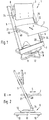
- the chair 1 emerging from the drawing is intended in particular for children and adolescents.
- the seat 2 and the backrest 3 therefore have no fixed predetermined height. Rather, the seat 2 and backrest 3 can be adjusted independently of one another in each case by means of a holding device over a height adjustment range, so that the height depends on the height of the user and whose proportions can be adjusted.
- the seat 2 can also be adjusted in the direction of depth from front to back or vice versa according to arrow 4, so that the seat depth can also be adjusted.
- FIG. 2 and 3 show two sitting positions. 2 seat and backrest assume approximately the height position required for an adult with a correspondingly adjusted seat depth. In Fig. 3, however, the seat and backrest are pushed down and the seat is pushed backwards so that a child can sit.
- the chair 1 has a chair frame which contains two holding bars 5, 6 which extend from bottom to top and which run on both sides of the seat 2, so that the seat 2 is arranged between the holding bars 5, 6.
- the holding bars 5, 6 also have, at least in the height adjustment range, in the expedient exemplary embodiment over their entire length, a continuously constant inclination which extends from the front bottom to the rear top. Due to this inclination, the seat 2 and backrest 3 are shifted backwards when the upward adjustment is carried out, so that the center of gravity of the heavier user at an older age is accordingly shifted backwards, which increases the stability elevated.
- the linear spar shape also results in an adjustment range that extends practically over the entire spar length. If there were bends or the like on the bars. available, the seat or the backrest could not be moved or only with difficulty over these points.
- the two holding bars 5, 6 are each connected to one another at their lower end and at their upper end area by means of a cross member 7 or 8, so that the holding bars 5, 6 and the cross members 7, 8 result in a rectangular structure.
- the lower cross member 7 is connected to a foot part 9 of the chair frame standing on the floor, so that the said rectangular structure protrudes from the foot part 9.
- the foot part 9 can be provided with casters 10, by means of which the chair stands on the floor.
- the castors 10 are, as is usual with chairs, distributed over the circumference and are present in such a number and radial projection that the chair cannot tip over.
- the foot part 9 is divided into a foot part part 11 on the bottom side and into a foot part part 12 which is rotatably mounted thereon and faces the lower cross member 7.
- the vertical axis of rotation line 13 is located in the center of the foot part 9.
- the user sitting on the chair can therefore be with turn the standing foot section 11 around the axis line 13 in a circle.
- the holding bars 5, 6 are unsupported with the exception of their lower end region towards the foot part 9 or towards the floor, so that they can be seen from the upper crossmember 8 and the seat and backrest mounting, projecting upwards at an angle. Given a corresponding cross-sectional shape of the holding bars 5, 6, this results in an elastic bendability of the holding bars 5, 6, so that the user can rock backwards or forwards depending on where he is shifting his weight.
- the foot part 9 has a connecting element 14 which connects the lower cross member 7 to the foot part 9 and which is bent in the direction of travel of the holding bars 5, 6.
- the connecting element 14 thus holds the lower crossmember 7 and, via this, the holding bars 5, 6, the seat 2 and the backrest 3 on the foot part 9, whereby a so-called swinging connection is obtained by the aforementioned bend, so that the chair also points at this point and can bob here and there. That on the fastener 14 vibration behavior to be traced back alone can be sufficient so that the holding bars 5, 6 could also be completely rigid in the presence of such a connecting element.
- the connecting element 14 and / or the holding bars 5, 6 are made of wood, and expediently consist of lamella-like, layers of wood glued together.
- the lower cross-member 7, which connects the holding bars 5, 6 and the connecting element 14, is made of metal, aluminum being particularly suitable.
- the cross members 7, 8, the seat 2 and the backrest 3 can be dismantled with the holding bars 5, 6 and the lower cross member 7 can be dismantled with the foot part 9.
- the individual parts resulting from the exploded view according to FIG. 4 result.
- This dismantling and the simple assembly are favored by the simple rectangular shape of the structure represented by the holding bars 5, 6 and the two cross members 7, 8.
- the lower cross member 7 is plugged onto the foot part 14, in the exemplary embodiment onto the connecting element 14, and the two holding bars 5, 6 are inserted into the lower cross member 7.
- the lower cross member 7 for this purpose on its underside in the middle a plug opening 15 for receiving a plug extension 16 of the connecting element 14 and on its upper side in the area of the two crossbar ends in each case a plug recess 17 or 18 for inserting the two Holders 5, 6 has.
- a screw connection can take place.
- the upper crossmember 8 is formed by a metal round rod, against the end faces of which the holding bars 5, 6 are pulled with the aid of screws, not shown. It goes without saying that the upper crossmember 8 could also be designed differently and / or connected in a different way to the holding bars 5, 6.
- the holding bars 5, 6 have an essentially rectangular cross section, the outer surface facing away from the seat, which faces the viewer in FIGS. 2 and 3 in the holding bar 5, can be rounded off primarily for optical reasons.
- the seat 2 and the backrest 3 are adjustably guided in the longitudinal direction of the holding bars 5, 6 and can be locked in the respective height position.
- a holding device 19 or 20 is provided in each case.
- the holding device 19 of the seat 2 has a holding piece 21 or 22, which can be adjusted in terms of height, for each spar 5 or 6, the two holding pieces 21, 11 or the like via a connecting rod 23. are firmly connected to each other, so that there is a rigid unit.
- the holding device 20 of the backrest 3 is constructed in the same way in the exemplary embodiment and has two corresponding holding pieces 24, 25 which are inserted in a height-adjustable manner on the spars 5, 6 and which or the like are connected via a connecting rod 26. are firmly connected.
- the procedure can be followed by first connecting the two holding bars 5, 6 to the lower crossmember 7, which can already be plugged onto the connecting element 14, after which the seat 2 by means of the holding pieces 21, 22 and the backrest 3 by means of the holding pieces 24, 25 are on the holding bars 5, 6 and bring them into the correct altitude. Then only the upper cross member 8 needs to be attached.
- the holding pieces 21, 22 and 24, 25 are plugged on in the exemplary embodiment from the end faces of the holding bars 5, 6 in the longitudinal direction of the bar.
- the holding pieces could enclose the holding bars all around.
- the holding pieces 21-25 encompass the respective facing holding bar 5, 6 in a U-like manner.
- the crossbar of the U rests on the inner surface 27 and 28 of the holding bar 5 and 6 facing the seat and the backrest, so that the two holding piece legs 29, 30 (see FIG. 6 for the holding piece 22) on the front side and the Rear of the respective holding bar are arranged.
- the arrangement is expediently such that at least one of the holding piece limbs, in the exemplary embodiment the rear holding piece limb 30, is angled at its free end towards the relevant holding bar 5 or 6 and with its angled end region 31 into a longitudinal groove 32 or 33 of the holding bar 5 or 6 engages so that there is a plug connection secured in all directions.
- an end area corresponding to the angled end area 31 could also engage behind the relevant holding bar as a whole, so that it would be arranged on the outer surface of the bar.
- the longitudinal groove 32 and 33 is located in particular optical reasons on the back of the respective spar.
- the holding pieces 21, 22, 24, 25, like the holding devices 19, 20, consist of metal.
- the holding bars 5, 6 each have a row of holes 34 extending in their longitudinal direction (only the row of holes of the bar 6 is visible in the drawing, on the other holding beam 5, however, the same conditions are present), which is a seat-side locking member 35 (for spar 5) or 36 (for spar 6) and a back-side locking member 37 (for spar 5) or 38 (for spar 6) is assigned to each holding device.
- the locking members 35-38 are adjustable between a locking position and a release position, the locking member engaging in the respective height position of the seat or the backrest in the hole of the relevant row of holes 34 opposite it.
- the two seat-side locking members 35, 36 or the two back-side locking members 37, 38 must therefore be moved into their release position, in which they no longer engage in the adjacent row of spar holes.
- the locking members 35 - 38 can by spring force in their locking position are held so that the transfer into the release position takes place against the spring force.
- the associated springs have been omitted in the drawing for the sake of clarity.
- the row of holes 28 is expediently located on the spar inner surface 27 or 28 facing the other spar.
- the two locking members 35, 36 and 37, 38 of the respective holding device 19 and 20 arranged within the hollow connecting rod 23 and 26 and each can be actuated by means of an actuating piece 39, 40 or 41, 42 penetrating a recess in the wall of the connecting rod.
- the two actuating pieces 39, 40 or 41, 42 and thus the locking members 35, 36 or 37, 38 connected to them can be adjusted in the longitudinal direction of the rod.
- the backrest 3 is fastened to the connecting rod 26, wherein in the exemplary embodiment it is screwed onto two intermediate pieces 43, 44, which in turn sit on the connecting rod 26.
- the seat 2 is not only as described adjustable in height, but also in the depth direction 4, for which purpose the seat 2 is arranged on the holding device 19 so as to be adjustable in the depth direction 4 by means of a depth adjustment device 45. In the embodiment according to FIGS. 1 to 7, this depth adjustment of the seat 2 is independent of the height adjustment.
- the holding device 19 has a guide bar 46 or 47 in each of the two holding pieces 21, 22, which is firmly connected to the holding piece in question and protrudes therefrom toward the seat 2.
- the guide bar can be formed by the horizontal leg of an angle piece 48 or 49 welded to the respective holding piece 21 or 22, the vertical leg 50 or 51 of which is placed on the inside of the respective holding piece and has a triangular shape which extends to the front.
- Each guide bar 46 or 47 engages in a guide groove 52 or 53 arranged on the relevant seat side, so that the seat 2 rests on the guide bars 46, 47 so as to be displaceable in the depth direction 4.
- the depth adjustment device has at least one row of latching recesses 54 arranged on the seat 2 and extending in the depth direction 4, to which is assigned a latching member 55 arranged on the holding device 19, which is located between a latching recess opposite to it in the respective depth position of the seat 2 54 engaging effective position and an inactive position releasing the seat 2 for displacement is adjustable.
- such a row of latching recesses with an associated latching member is provided on both sides of the seat 2.
- the respective row of locking recesses 54 is located in a perforated strip 56 or 57 fastened to the underside of the seat 2, which at the same time delimits the guide groove 32 or 33 on the underside.
- the perforated strips 56, 57 are formed in the exemplary embodiment by metal strips.
- the respective locking member 55 sits at one end of a two-armed actuating lever 58 which is arranged below the seat on the holding device and can be pivoted about a pivot axis 60 against the force of a spring 59.
- the pivot axis 60 is parallel to the connecting rod 23 from the relevant holding piece 21 or 22, in the embodiment of the welded to the holding piece Angle piece 48 or 49.
- the locking recesses 54 shown are a row of holes into which the bolt-like locking member 55 is immersed in the active position.
- the seat 2 can, as mentioned, be adjusted in the depth direction 4 at any height regardless of this.
- the depth adjustment of the seat takes place automatically as a function of the height adjustment, in such a way that when the seat is adjusted upwards it simultaneously adjusts to the front and when it is adjusted downwards to the rear.
- the inclined up / down movement of the seat is coupled with the adjustment of the seat in the depth direction. That way it fits the seat depth automatically adjusts to the respective seat height with a reasonably chosen path ratio. It is always the case that when the seat height is low for children, the seat must be moved further back, or if the seat is above for adults, the seat must be moved further forward.
- a transmission ratio that is constant over the height adjustment range can be selected between the height adjustment and the depth adjustment, that is to say the distance traveled by the seat in the depth direction is entirely proportional to the distance covered along the holding bars 5, 6.
- FIG. 8 Such a possibility of a depth adjustment derived from the height adjustment can be seen from FIG. It should be noted that this chair, with the exception of the depth adjustment of the seat, can be constructed in the same way as described above, the same reference numerals being entered in FIG. 8 for corresponding parts with the addition of an "a".
- a rack 61 extending in its longitudinal direction is arranged on at least one holding bar 5a and can be embedded in a spar groove 62. Furthermore, at least one toothed rack 63 running in the depth direction 4 is arranged on the seat 2a, the side view (Fig. 8) the spar rack 61 crosses, but runs in a different plane than this. Between the two racks 61, 63, a gear transmission 64 is arranged, which contains a driving gear 65 meshing with the rack 61 of the holding bar 5a and a driven gear 66 meshing with the rack 63 of the seat 2a. The gear transmission 64 is arranged on the holding device 19a of the seat, of which the holding piece 21a guided on the holding bar 5a is visible in FIG. 8.
- the spar rack 61 is on the spar rear.
- the teeth of the seat-side rack 63 point downwards.
- the driving gear 65 which meshes with the spar-side rack 61, sits on a gear transverse to the depth and Height-adjusting shaft 67, on which the seat-side driven gear 66 sits coaxially with the driving gear 65, which has a smaller diameter than the driving gear 65 and meshes with the seat-side rack 63.
- other gear transmissions for example a bevel gear transmission, can also be used.
- the gear mechanism 65, 66 which maintains its position within the holding device, is taken along, the driving gear 65 and with it, via the shaft 67, the driven gear 66 rotating clockwise, which a forward pushing, in Fig. 8 to the right, of the seat 2a results.
- the shaft 67 which is rotatably mounted on the holding device 19a for the seat 2a, runs to the other side of the seat and carries the corresponding gearwheels there.
- a depth groove guide groove 52a is provided on both sides of the seat, into which a guide bar 46a of the holding device 19a engages, which is the same as the guide bars 46 , 47 can be formed by being formed by the horizontal leg of an angle piece 48a which is fixedly connected to the holding piece 21a and which projects from the holding piece 21a to the opposite spar.
- the lateral retaining groove 52a of the seat 2a could also be designed as described above.
- the guide groove 52a is formed by a separate groove strip 68, on which the seat 2a is attached in a suitable manner.
- the seat-side rack 63 can be located on the slot bar 68, but also at another location on the seat.
- the seat 2a is firmly connected to the rack 63 on the seat side.
- a further possibility of seat adjustment in this direction is provided by hand, so that the seat depth can be further adjusted to the personal needs of the user.
- the seat is subdivided into a seat part forming the seat surface and a seat part carrying the seat-side rack, the seat part forming the seat surface being adjustable in the depth direction on the seat part carrying the rack and being lockable in the respective depth position with the latter.
- FIG. 8 This variant is not shown separately, but it is easy to imagine using FIG. 8.
- the seat 2a would correspond to the seat part forming the seat surface and the grooved strip 68 to the seat part bearing the toothed rack. Between the two "seat parts" 2a and 68, only a sliding guide with associated locking would then have to be provided, as is similar to the embodiment described earlier in the form of the row of locking recesses 54 and locking element 55 is available.
Landscapes
- Chair Legs, Seat Parts, And Backrests (AREA)
- Chairs For Special Purposes, Such As Reclining Chairs (AREA)
Applications Claiming Priority (2)
| Application Number | Priority Date | Filing Date | Title |
|---|---|---|---|
| DE19504542A DE19504542B4 (de) | 1995-02-11 | 1995-02-11 | Stuhl |
| DE19504542 | 1995-02-11 |
Publications (2)
| Publication Number | Publication Date |
|---|---|
| EP0726045A2 true EP0726045A2 (fr) | 1996-08-14 |
| EP0726045A3 EP0726045A3 (fr) | 1997-01-22 |
Family
ID=7753697
Family Applications (1)
| Application Number | Title | Priority Date | Filing Date |
|---|---|---|---|
| EP96100199A Withdrawn EP0726045A3 (fr) | 1995-02-11 | 1996-01-09 | Chaise |
Country Status (2)
| Country | Link |
|---|---|
| EP (1) | EP0726045A3 (fr) |
| DE (1) | DE19504542B4 (fr) |
Cited By (7)
| Publication number | Priority date | Publication date | Assignee | Title |
|---|---|---|---|---|
| EP0808593A3 (fr) * | 1996-05-22 | 1999-08-18 | Azur P.A.M.O.M. | Chaise haute à configuration variable |
| FR2826560A1 (fr) * | 2001-06-28 | 2003-01-03 | T 4 Atel | Chaise modulable pour enfant |
| EP1077188B1 (fr) * | 1999-08-10 | 2003-01-29 | Costruzioni Meccaniche Crizaf S.p.A. | Conveyeur avec table de support pour un conteneur |
| GB2398488A (en) * | 2002-12-31 | 2004-08-25 | Mission Hills Invest Corp | A chair with a rack and pinion assembly for adjusting the height of a seat member |
| WO2008019809A1 (fr) * | 2006-08-18 | 2008-02-21 | Pius Ponticelli | Chaise |
| CN102551389A (zh) * | 2010-12-15 | 2012-07-11 | 郭莉 | 可调式学生用椅 |
| GB2495488A (en) * | 2011-10-07 | 2013-04-17 | Radclyffe Furniture Ltd | Chair with seat depth and seat height adjustment |
Families Citing this family (4)
| Publication number | Priority date | Publication date | Assignee | Title |
|---|---|---|---|---|
| DE19733785A1 (de) | 1997-08-05 | 1999-02-11 | Loh Kg Hailo Werk | Stuhl |
| DE19901076A1 (de) | 1999-01-14 | 2000-07-20 | Moll Sys & Funktions Moebel | Stuhl |
| CN105361494A (zh) * | 2015-11-17 | 2016-03-02 | 彭先仲 | 学习椅 |
| DE102016011221B4 (de) | 2016-09-16 | 2021-11-11 | Löffler GmbH | Hartschalenstuhl |
Family Cites Families (3)
| Publication number | Priority date | Publication date | Assignee | Title |
|---|---|---|---|---|
| DE9003042U1 (de) * | 1990-03-13 | 1990-07-05 | Hilgers-Silberberg, Jürgen | Kindersitzmöbel |
| DE4305841B4 (de) * | 1993-02-26 | 2008-07-31 | VS Vereinigte Spezialmöbelfabriken GmbH & Co. KG | Stuhl mit in der Höhe verstellbarem Sitz |
| DE9410679U1 (de) * | 1994-07-02 | 1994-08-25 | Georg Schardt KG, 96268 Mitwitz | Höhenverstellbarer Stuhl |
-
1995
- 1995-02-11 DE DE19504542A patent/DE19504542B4/de not_active Expired - Fee Related
-
1996
- 1996-01-09 EP EP96100199A patent/EP0726045A3/fr not_active Withdrawn
Cited By (9)
| Publication number | Priority date | Publication date | Assignee | Title |
|---|---|---|---|---|
| EP0808593A3 (fr) * | 1996-05-22 | 1999-08-18 | Azur P.A.M.O.M. | Chaise haute à configuration variable |
| EP1077188B1 (fr) * | 1999-08-10 | 2003-01-29 | Costruzioni Meccaniche Crizaf S.p.A. | Conveyeur avec table de support pour un conteneur |
| FR2826560A1 (fr) * | 2001-06-28 | 2003-01-03 | T 4 Atel | Chaise modulable pour enfant |
| GB2398488A (en) * | 2002-12-31 | 2004-08-25 | Mission Hills Invest Corp | A chair with a rack and pinion assembly for adjusting the height of a seat member |
| US6899394B2 (en) | 2002-12-31 | 2005-05-31 | Mission Hills Investment Corporation | Chair with a rack-and-pinion assembly for adjusting height of a seat member |
| GB2398488B (en) * | 2002-12-31 | 2005-09-07 | Mission Hills Invest Corp | Chair with a rack-and-pinion assembly for adjusting height of a seat member |
| WO2008019809A1 (fr) * | 2006-08-18 | 2008-02-21 | Pius Ponticelli | Chaise |
| CN102551389A (zh) * | 2010-12-15 | 2012-07-11 | 郭莉 | 可调式学生用椅 |
| GB2495488A (en) * | 2011-10-07 | 2013-04-17 | Radclyffe Furniture Ltd | Chair with seat depth and seat height adjustment |
Also Published As
| Publication number | Publication date |
|---|---|
| DE19504542B4 (de) | 2006-11-02 |
| DE19504542A1 (de) | 1996-08-14 |
| EP0726045A3 (fr) | 1997-01-22 |
Similar Documents
| Publication | Publication Date | Title |
|---|---|---|
| DE69413551T2 (de) | Klapptisch | |
| EP1020138B1 (fr) | Chaise | |
| DE3235361C2 (fr) | ||
| DE2459908C3 (de) | Ausziehvorrichtung für eine Fußstütze bei einem Lehnsessel | |
| DE3630527A1 (de) | Vorrichtung fuer die hoehenverstellung der rueckenstuetze an einem stuhl | |
| EP0264555A2 (fr) | Chaise, notamment chaise de bureau, avec dossier réglable en hauteur | |
| EP1849378A1 (fr) | Dispositif destiné à la fixation de sièges | |
| EP0726045A2 (fr) | Chaise | |
| DE4317610C2 (de) | Höhenverstellbare Armlehne für einen Stuhl | |
| EP0775458A1 (fr) | Siège avec surface d'appui des genoux | |
| DE3728717C2 (de) | Fußstütze | |
| DE2048460A1 (de) | Dreh oder Kippeinrichtung fur einen kippbaren Stuhlsitz | |
| DE4039097C2 (de) | Höhenverstellbarer Fuß für Möbel | |
| DE10220841B4 (de) | Stuhl mit Rückenlehne, die zur Einstellung der Sitztiefe relativ gegenüber dem Sitzteil verstellbar ist | |
| DE9404758U1 (de) | Möbel, insbesondere Sitzmöbel, mit verschiebbaren Kissen, insbesondere mit verschiebbaren Rückenkissen | |
| DE4317609C2 (de) | Stuhl, insbesondere Bürostuhl | |
| DE8032031U1 (de) | Polstersessel oder -couch mit verstellbarem sitz- und rueckenpolster | |
| DE2709960A1 (de) | Sitzmoebel, insbesondere drehbarer arbeitsstuhl | |
| EP0213236A2 (fr) | Dispositif de type rayonnage | |
| AT391061B (de) | Tisch | |
| DE29906745U1 (de) | Sitzmöbel | |
| DE1404635C (de) | Sessel mit einstellbarer, zwanglaufig voneinander abhangigen Sitzhohe und Sitz tiefe | |
| EP0551880B1 (fr) | Table de travail ou bureau | |
| EP1421877A1 (fr) | Meuble utilisant de la matière plastique recyclée | |
| WO1990007889A1 (fr) | Chaise |
Legal Events
| Date | Code | Title | Description |
|---|---|---|---|
| PUAI | Public reference made under article 153(3) epc to a published international application that has entered the european phase |
Free format text: ORIGINAL CODE: 0009012 |
|
| AK | Designated contracting states |
Kind code of ref document: A2 Designated state(s): AT BE CH DE DK ES FR GB IT LI LU NL PT |
|
| PUAL | Search report despatched |
Free format text: ORIGINAL CODE: 0009013 |
|
| AK | Designated contracting states |
Kind code of ref document: A3 Designated state(s): AT BE CH DE DK ES FR GB IT LI LU NL PT |
|
| 17P | Request for examination filed |
Effective date: 19970129 |
|
| STAA | Information on the status of an ep patent application or granted ep patent |
Free format text: STATUS: THE APPLICATION IS DEEMED TO BE WITHDRAWN |
|
| 18D | Application deemed to be withdrawn |
Effective date: 19980801 |