EP0726358A2 - Vorrichtung zum Imprägnieren von Bahnen aus porösem Material - Google Patents
Vorrichtung zum Imprägnieren von Bahnen aus porösem Material Download PDFInfo
- Publication number
- EP0726358A2 EP0726358A2 EP95118185A EP95118185A EP0726358A2 EP 0726358 A2 EP0726358 A2 EP 0726358A2 EP 95118185 A EP95118185 A EP 95118185A EP 95118185 A EP95118185 A EP 95118185A EP 0726358 A2 EP0726358 A2 EP 0726358A2
- Authority
- EP
- European Patent Office
- Prior art keywords
- chamber
- roller
- line
- section
- slot
- Prior art date
- Legal status (The legal status is an assumption and is not a legal conclusion. Google has not performed a legal analysis and makes no representation as to the accuracy of the status listed.)
- Granted
Links
Images
Classifications
-
- B—PERFORMING OPERATIONS; TRANSPORTING
- B29—WORKING OF PLASTICS; WORKING OF SUBSTANCES IN A PLASTIC STATE IN GENERAL
- B29B—PREPARATION OR PRETREATMENT OF THE MATERIAL TO BE SHAPED; MAKING GRANULES OR PREFORMS; RECOVERY OF PLASTICS OR OTHER CONSTITUENTS OF WASTE MATERIAL CONTAINING PLASTICS
- B29B15/00—Pretreatment of the material to be shaped, not covered by groups B29B7/00 - B29B13/00
- B29B15/08—Pretreatment of the material to be shaped, not covered by groups B29B7/00 - B29B13/00 of reinforcements or fillers
- B29B15/10—Coating or impregnating independently of the moulding or shaping step
- B29B15/12—Coating or impregnating independently of the moulding or shaping step of reinforcements of indefinite length
- B29B15/122—Coating or impregnating independently of the moulding or shaping step of reinforcements of indefinite length with a matrix in liquid form, e.g. as melt, solution or latex
-
- B—PERFORMING OPERATIONS; TRANSPORTING
- B05—SPRAYING OR ATOMISING IN GENERAL; APPLYING FLUENT MATERIALS TO SURFACES, IN GENERAL
- B05B—SPRAYING APPARATUS; ATOMISING APPARATUS; NOZZLES
- B05B3/00—Spraying or sprinkling apparatus with moving outlet elements or moving deflecting elements
- B05B3/02—Spraying or sprinkling apparatus with moving outlet elements or moving deflecting elements with rotating elements
- B05B3/12—Spraying or sprinkling apparatus with moving outlet elements or moving deflecting elements with rotating elements with spray booms or the like rotating around an axis by means independent of the liquid or other fluent material discharged
Definitions
- the invention relates to a device according to the preamble of patent claim 1.
- the continuous web drives the boundary layer of the impregnating agent adhering to its surface into the narrowed area of the chamber.
- the pressure in the chamber increases towards the outlet slot.
- pressures in the vicinity of the outlet slot are achieved which are clearly above 1 MPa. If the impregnating agent is supplied via a pressure pump, the static pressure generated by the pressure pump is added to the dynamic pressure generated in the chamber.
- the invention has for its object to further improve the effectiveness of the device.
- a roller 5 is partially immersed, which is rotatably mounted in a top frame, not shown, and is provided with a drive, also not shown.
- the base body 2 has an arcuate cross section and approximately forms a half cylinder.
- a chamber 6 is located between the inner surface of the base body 2 and the outer surface of the roller 5.
- the chamber 6 has an inlet slot 7 and an outlet slot 8 for a paper web 43 to be coated.
- a feed line 9 for an impregnation agent opens into the chamber 6 in the vicinity of the inlet slot 7.
- the feed line 9 penetrates the base body 2 and is connected to a pressure pump, not shown.
- a sealing block 10 is arranged, which extends from the end wall 3 to the end wall 4.
- strips 11 and grooves 12 are arranged alternately, so that the cross section visible in FIG. 1 roughly resembles a comb.
- the broken line which illustrates the outer surfaces of the strips in cross section, is adapted to the roll cross section, so that there are 5 narrow gaps between the outer surface of the strips 11 and the outer surface of the roller.
- the width of the column can be changed by an approximately radial fine adjustment, shown as screw 13 in FIG. 1.
- Each groove 12 is provided with a plurality of drain openings 14 distributed over its length, which penetrate the sealing block 10 and open into a channel 15 from which a drain pipe 16 extends.
- a corresponding sealing block 17 is attached to the outlet gap 8.
- the end walls 3, 4 are connected to the base body 2 by screws 18, 19.
- a sealing plate 20 is clamped between end wall 3 and base body 2, and a sealing plate 21 between end wall 4 and base body 2.
- the sealing plates 20, 21 are approximately semicircular and each have a recess in the area of the shaft journal 22. They are made of a wear-resistant plastic that has a low coefficient of friction against metal.
- the device differs from the prior art in particular in that the cross section of the chamber 6 is narrowed and expanded again several times along the path from the inlet slot 7 to the outlet slot 8.
- the line which represents the inner wall 23 of the base body 2 resembles a sawtooth curve. In the embodiment shown in FIG. 1, it has five teeth, in practice up to about fifteen teeth.
- Each sawtooth has a flank 24 that rises gently in the direction of movement and a steeply descending flank 25 behind the tooth tip.
- the tooth tip is as close as possible to the surface of the roller 5, but is sufficiently large to damage the web to be impregnated, in particular web tears. to avoid. He is e.g. adjustable by lifting the roller 5 and can thus be adapted to the thickness of the web.
- the maximum distance between roller 5 and inner wall 23 is significantly larger.
- the chamber cross section is constant in a path section 27. For this section, the distance between the inner wall 23 and roller 5 is relatively narrow, approximately as at the tooth tips.
- a paper web 43 to be impregnated which wraps around the roller 5 approximately on half the circumference, is fed through the inlet slot 7 to the chamber 6.
- the impregnated sheet leaves the chamber 6 through the outlet slot 8.
- Impregnating agent is fed to the chamber 6 via the feed line 9, preferably under increased pressure up to about 1.0 MPa, preferably up to about 0.2 MPa.
- the inner wall 28 of the base body 2 is corrugated.
- the line which represents the inner wall 28 in cross section is a continuously curved wavy line. In the region of the wave crests, the distance between inner wall 28 and roller 5 is as small as trouble-free operation allows.
- a location-dependent dynamic pressure component is built up, which is larger in the area of the constrictions than in the area of the extensions.
Landscapes
- Engineering & Computer Science (AREA)
- Mechanical Engineering (AREA)
- Paper (AREA)
- Coating Apparatus (AREA)
- Application Of Or Painting With Fluid Materials (AREA)
- Treatment Of Fiber Materials (AREA)
- Reinforced Plastic Materials (AREA)
- Battery Electrode And Active Subsutance (AREA)
Abstract
Description
- Die Erfindung betrifft eine Vorrichtung gemäß dem Oberbegriff des Patentanspruchs 1.
- Aus der EP 0 173 519 B1, von der die Erfindung ausgeht, ist es bekannt, die Imprägnierung unter erhöhtem Druck durchzuführen. Dadurch kann eine erheblich größere Menge an Tränkungsmittel in das Substrat eingebracht werden als bei der drucklosen Imprägnierung. Es wird z.B. möglich, dichtere Papiere mit geringem Saugvermögen zu imprägnieren. Ferner eröffnet sich die Möglichkeit, Tränkungsmittel mit hoher Viskosität, d.h. mit hohem Feststoffgehalt und verringertem Lösemittelanteil, einzusetzen. Die erforderliche Druckerhöhung wird insbesondere dadurch erreicht, daß die Kammer, die das Tränkungsmittel aufnimmt, sich vom Einlaufschlitz in Richtung auf den Auslaufschlitz stetig verengt. Die durchlaufende Bahn treibt die an ihrer Oberfläche anhaftende Grenzschicht des Tränkungsmittels in den verengten Bereich der Kammer. Dadurch nimmt der Druck in der Kammer in Richtung auf den Auslaufschlitz zu. Bei Durchlaufgeschwindigkeiten von etwa 45 bzw. 60 m/s werden nach Angaben der genannten Schritt in der Nähe des Auslaufschlitzes Drücke erreicht, die deutlich über 1 MPa liegen. Wenn das Tränkungsmittel über eine Druckpumpe zugeführt wird, addiert sich der von der Druckpumpe erzeugte statische Druck zu dem in der Kammer erzeugten dynamischen Druck.
- Der Erfindung liegt die Aufgabe zugrunde, die Wirksamkeit der Vorrichtung noch weiter zu verbessern.
- Diese Aufgabe wird durch die kennzeichnenden Merkmale des Anspruchs 1 gelöst.
- Bevorzugte Ausführungen und Ausgestaltungen der Erfindung sind Gegenstand der Ansprüche 2 und 3.
- Die Zeichnung dient zur Erläuterung der Erfindung anhand von vereinfacht dargestellten Ausführungsbeispielen.
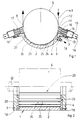
- Figur 1
- zeigt einen Querschnitt durch ein Ausführungsbeispiel.
- Figur 2
- zeigt für das Ausführungsbeispiel der Figur 1 einen Längsschnitt durch den Trog mit angedeuteter Walze.
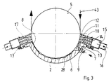
- Figur 3
- zeigt einen Querschnitt durch ein anderes Ausführungsbeispiel.
- In einen Trog 1, der im wesentlichen aus einem Grundkörper 2 und aus ebenen Stirnwänden 3, 4 besteht, taucht teilweise eine Walze 5 ein, die in einem nicht dargestellten heb- und senkbaren Obergestell drehbar gelagert und mit einem ebenfalls nicht dargestellten Antrieb versehen ist. Der Grundkörper 2 hat einen bogenförmigen Querschnitt und bildet annähernd einen Halbzylinder. Zwischen der Innenfläche des Grundkörpers 2 und der Mantelfläche der Walze 5 befindet sich eine Kammer 6. Die Kammer 6 hat einen Einlaufschlitz 7 und einen Auslaufschlitz 8 für eine zu beschichtende Papierbahn 43.
- In die Kammer 6 mündet in der Nähe des Einlaufschlitzes 7 eine Zuleitung 9 für ein Tränkungsmittel ein. Die Zuleitung 9 durchdringt den Grundkörper 2 und ist mit einer nicht dargestellten Druckpumpe verbunden.
- Am Einlaufschlitz 7 ist ein Dichtungsblock 10 angeordnet, der sich von der Stirnwand 3 bis zur Stirnwand 4 erstreckt. Auf der Seite, die der Walze 5 zugekehrt ist, sind abwechselnd Leisten 11 und Rillen 12 angeordnet, so daß der in Figur 1 sichtbare Querschnitt etwa einem Kamm gleicht. Die unterbrochene Linie, die im Querschnitt die Außenflächen der Leisten veranschaulicht, ist dem Walzenquerschnitt angepaßt, so daß zwischen den Außenfläche der Leisten 11 und der Mantelfläche der Walze 5 enge Spalte bestehen. Die Weite der Spalte läßt sich durch eine annähernd radiale Feineinstellung, in Figur 1 als Schraube 13 dargestellt, verändern. Jede Rille 12 ist mit mehreren über die Länge verteilten Abflußöffnungen 14 versehen, die den Dichtblock 10 durchdringen und in einen Kanal 15 einmünden, von dem ein Abflußrohr 16 ausgeht. Ein entsprechender Dichtungsblock 17 ist am Auslaufspalt 8 angebracht.
- Die Stirnwände 3, 4 sind durch Schrauben 18, 19 mit dem Grundkörper 2 verbunden. Zwischen Stirnwand 3 und Grundkörper 2 ist eine Dichtungsplatte 20 eingespannt, zwischen Stirnwand 4 und Grundkörper 2 eine Dichtungsplatte 21. Die Dichtungsplatten 20, 21 sind etwa halbkreisförmig und haben im Bereich des Wellenzapfens 22 je eine Ausnehmung. Hergestellt sind sie aus einem verschleißfesten Kunststoff, der gegen Metall einen niedrigen Reibungskoeffizienten hat.
- Vom Stand der Technik unterscheidet sich die Vorrichtung insbesondere dadurch, daß sich der Querschnitt der Kammer 6 längs des Weges vom Einlaufschlitz 7 zum Auslaufschlitz 8 mehrmals hintereinander verengt und wieder erweitert. In dem Querschnitt gemäß Figur 1 gleicht die Linie, die die Innenwand 23 des Grundkörpers 2 darstellt, einer Sägezahnkurve. Sie hat bei dem in Figur 1 dargestellten Ausführungsbeispiel fünf Zähne, in der Praxis bis zu etwa fünfzehn Zähne.
- Jeder Sägezahn hat eine in Bewegungsrichtung flach ansteigende Flanke 24 und hinter der Zahnspitze eine steil abfallende Flanke 25. Die Zahnspitze hat von dem Mantel der Walze 5 einen möglichst geringen Abstand, der aber ausreichend groß ist, um Beschädigungen der zu imprägnierenden Bahn, insbesondere Bahnrisse, zu vermeiden. Er ist z.B. durch Anheben der Walze 5 verstellbar und kann somit an die Dicke der Bahn angepaßt werden. Der maximale Abstand zwischen Walze 5 und Innenwand 23 ist deutlich größer. In der Nähe des Auslaufschlitzes 8 ist der Kammerquerschnitt in einem Wegabschnitt 27 konstant. Für diesen Abschnitt ist der Abstand zwischen Innenwand 23 und Walze 5 relativ eng, etwa wie an den Zahnspitzen.
- Im Betrieb wird eine zu tränkende Papierbahn 43, die die Walze 5 etwa auf der Hälfte des Umfangs umschlingt, durch den Einlaufschlitz 7 der Kammer 6 zugeführt. Die imprägnierte Bahn verläßt die Kammer 6 durch den Auslaufschlitz 8. Über die Zuleitung 9 wird der Kammer 6 Tränkungsmittel zugeführt, vorzugsweise unter erhöhtem Druck bis etwa 1,0 MPa, vorzugsweise bis etwa 0,2 MPa.
- Die Verengungen und Erweiterungen der Kammer 6 bewirken in Verbindung mit dem Schleppeffekt der hindurchbewegten Papierbahn, daß sich dem statischen Druck, mit dem das Tränkungsmittel zugeführt wird, eine ortsabhängige dynamische Druckkomponente überlagert. Über den ansteigenden Zahnflanken 24 baut sich ein Druckgradient auf, so daß der Druck in Richtung auf die Zahnspitzen ansteigt. Hinter jeder Zahnspitze fällt der Druck steil ab. Jede Stelle der Papierbahn 43 wird daher längs ihres Weges durch die Kammer 6 mehrmals wie ein Schwamm zusammengedrückt und wieder freigegeben. Dadurch wird das Tränkungsmittel intensiver in die Poren der Papierbahn hineingedrückt.
- Bei dem Ausführungsbeispiel gemäß Figur 3 ist die Innenwand 28 des Grundkörpers 2 gewellt. Die Linie, die im Quersschnitt die Innenwand 28 darstellt, ist eine stetig gekrümmte Wellenlinie. Im Bereich der Wellenberge ist der Abstand zwischen Innenwand 28 und Walze 5 so gering, wie es ein störungsfreier Betrieb zuläßt.
- Die Wirkungsweise ist ähnlich wie bei dem anderen Ausführungsbeispiel: es baut sich eine ortsabhängige dynamische Druckkomponente auf, die im Bereich der Verengungen größer ist als im Bereich der Erweiterungen.
Claims (3)
- Vorrichtung zum Imprägnieren von Bahnen aus porösem Material, insbesondere aus Papier oder Pappe, mit einem flüssigen Tränkungsmittel, insbesondere Harz, unter erhöhtem Druck
mit einer Walze, die um eine waagerechte Achse drehbar und antreibbar ist,
mit einem Trog, in den die Walze teilweise eintaucht, wobei sich zwischen der Innenfläche des Troges und der Mantelfläche der Walze eine Kammer befindet,
mit einer in die Kammer einmündenden Zuleitung für das Tränkungsmittel,
mit einem Einlaufschlitz und einem Auslaufschlitz für die zu imprägnierende Bahn
und mit Dichtungen am Einlaufschlitz und am Auslaufschlitz,
dadurch gekennzeichnet,
daß sich die Kammer (6) auf der Strecke vom Einlaufschlitz (7) zum Auslaufschlitz (8) mehrmals hintereinander verengt und wieder erweitert. - Vorrichtung nach Anspruch 1, dadurch gekennzeichnet, daß die Linie, die die im Querschnitt die Innenfläche (23) des Grundkörpers (2) darstellt, eine Sägezahnlinie ist.
- Vorrichtung nach Anspruch 1, dadurch gekennzeichnet, daß die Linie, die im Querschnitt die Innenfläche (28) des Grundkörpers (2) darstellt, eine Wellenlinie ist.
Applications Claiming Priority (2)
| Application Number | Priority Date | Filing Date | Title |
|---|---|---|---|
| DE29501919U DE29501919U1 (de) | 1995-02-07 | 1995-02-07 | Vorrichtung zum Imprägnieren von Bahnen aus porösem Material |
| DE29501919U | 1995-02-07 |
Publications (3)
| Publication Number | Publication Date |
|---|---|
| EP0726358A2 true EP0726358A2 (de) | 1996-08-14 |
| EP0726358A3 EP0726358A3 (de) | 1997-05-14 |
| EP0726358B1 EP0726358B1 (de) | 2000-02-09 |
Family
ID=8003512
Family Applications (1)
| Application Number | Title | Priority Date | Filing Date |
|---|---|---|---|
| EP95118185A Expired - Lifetime EP0726358B1 (de) | 1995-02-07 | 1995-11-18 | Vorrichtung zum Imprägnieren von Bahnen aus porösem Material |
Country Status (6)
| Country | Link |
|---|---|
| US (1) | US6174369B1 (de) |
| EP (1) | EP0726358B1 (de) |
| AT (1) | ATE189723T1 (de) |
| CA (1) | CA2168823A1 (de) |
| DE (2) | DE29501919U1 (de) |
| ES (1) | ES2142990T3 (de) |
Cited By (1)
| Publication number | Priority date | Publication date | Assignee | Title |
|---|---|---|---|---|
| WO2010040781A3 (de) * | 2008-10-07 | 2011-03-10 | Kaindl Decor Gmbh | Vorrichtung zum imprägnieren von bahnförmigen materialien mit wärmehärtbarem imprägnierharz |
Families Citing this family (2)
| Publication number | Priority date | Publication date | Assignee | Title |
|---|---|---|---|---|
| DE19963151A1 (de) * | 1999-12-24 | 2001-07-05 | Vits Maschinenbau Gmbh | Anlage zum Imprägnieren von durchlaufenden Bahnen |
| CN116038942A (zh) * | 2022-12-23 | 2023-05-02 | 南通万达摩擦材料有限公司 | 纤维增强的汽车离合器面片料用浸渍设备 |
Citations (1)
| Publication number | Priority date | Publication date | Assignee | Title |
|---|---|---|---|---|
| EP0173519A1 (de) | 1984-08-16 | 1986-03-05 | Miply Equipment Inc. | Verfahren und Vorrichtung zur Drucktränkung eines Substrats |
Family Cites Families (13)
| Publication number | Priority date | Publication date | Assignee | Title |
|---|---|---|---|---|
| US419331A (en) * | 1890-01-14 | Process of scouring and dyeing | ||
| US2542819A (en) * | 1947-01-21 | 1951-02-20 | American Cyanamid Co | Method of impregnating fibrous sheet materials |
| AT173519B (de) | 1950-08-05 | 1952-12-27 | Rosenthal Isolatoren Gmbh | Elektrischer Heizkörper |
| US2779183A (en) * | 1955-02-18 | 1957-01-29 | Fornelli Domenico | Apparatus for liquid treatment of a web of fabric |
| US3626449A (en) * | 1970-01-23 | 1971-12-07 | Komatsu Seiren Co | Apparatus for continuously relaxing textile material in a treating liquid |
| NL7102161A (de) * | 1970-08-14 | 1972-02-16 | ||
| US3730680A (en) * | 1972-01-05 | 1973-05-01 | Du Pont | Process for extracting solvent from polyamide filaments |
| US4982686A (en) * | 1986-07-09 | 1991-01-08 | Miply Equipment, Inc. | Converging chamber saturator with removable insert |
| US4849261A (en) * | 1986-07-09 | 1989-07-18 | Miply Equipment, Inc. | Pattern forming saturator and method |
| US4702943A (en) * | 1986-07-09 | 1987-10-27 | Miply Equipment, Inc. | Pattern forming saturator and method |
| US4740391A (en) * | 1986-07-09 | 1988-04-26 | Miply Equipment, Inc. | Pattern forming saturator and method |
| US4915989A (en) * | 1988-08-09 | 1990-04-10 | Miply Equipment, Inc. | Pressure saturator and method |
| DE4429939C1 (de) * | 1994-08-24 | 1995-08-17 | Vits Maschinenbau Gmbh | Vorrichtung zum Imprägnieren von Bahnen aus porösem Material |
-
1995
- 1995-02-07 DE DE29501919U patent/DE29501919U1/de not_active Expired - Lifetime
- 1995-11-18 DE DE59507787T patent/DE59507787D1/de not_active Expired - Fee Related
- 1995-11-18 AT AT95118185T patent/ATE189723T1/de not_active IP Right Cessation
- 1995-11-18 ES ES95118185T patent/ES2142990T3/es not_active Expired - Lifetime
- 1995-11-18 EP EP95118185A patent/EP0726358B1/de not_active Expired - Lifetime
-
1996
- 1996-02-05 CA CA002168823A patent/CA2168823A1/en not_active Abandoned
- 1996-02-05 US US08/596,734 patent/US6174369B1/en not_active Expired - Fee Related
Patent Citations (1)
| Publication number | Priority date | Publication date | Assignee | Title |
|---|---|---|---|---|
| EP0173519A1 (de) | 1984-08-16 | 1986-03-05 | Miply Equipment Inc. | Verfahren und Vorrichtung zur Drucktränkung eines Substrats |
Cited By (5)
| Publication number | Priority date | Publication date | Assignee | Title |
|---|---|---|---|---|
| WO2010040781A3 (de) * | 2008-10-07 | 2011-03-10 | Kaindl Decor Gmbh | Vorrichtung zum imprägnieren von bahnförmigen materialien mit wärmehärtbarem imprägnierharz |
| CN102216525A (zh) * | 2008-10-07 | 2011-10-12 | 凯得装饰有限公司 | 用能热硬化的浸渍树脂浸渍幅料状材料的装置 |
| RU2467115C1 (ru) * | 2008-10-07 | 2012-11-20 | Кайндль Декор Гмбх | Устройство для пропитки полосовых материалов термоотверждаемой пропиточной смолой |
| CN102216525B (zh) * | 2008-10-07 | 2013-11-06 | 凯得装饰有限公司 | 用能热硬化的浸渍树脂浸渍幅料状材料的装置 |
| US8945679B2 (en) | 2008-10-07 | 2015-02-03 | Kaindl Decor Gmbh | Apparatus for impregnating web-like materials with thermally curable impregnating resin |
Also Published As
| Publication number | Publication date |
|---|---|
| ES2142990T3 (es) | 2000-05-01 |
| DE59507787D1 (de) | 2000-03-16 |
| EP0726358A3 (de) | 1997-05-14 |
| EP0726358B1 (de) | 2000-02-09 |
| ATE189723T1 (de) | 2000-02-15 |
| DE29501919U1 (de) | 1995-04-06 |
| US6174369B1 (en) | 2001-01-16 |
| CA2168823A1 (en) | 1996-08-08 |
Similar Documents
| Publication | Publication Date | Title |
|---|---|---|
| EP0003790B1 (de) | Vorrichtung zum Beschichten einer sich bewegenden Bahn | |
| AT392602B (de) | Streicheinrichtung zur beschichtung laufender warenbahnen | |
| EP0682728B1 (de) | Dosiersystem für vorrichtung zum beschichten von materialbahnen, insbesondere papier- oder kartonbahnen | |
| DE2413280C3 (de) | Naßpresse für Papiermaschinen | |
| DE2228685B2 (de) | Beschichtungsvorrichtung | |
| DE69214090T2 (de) | Verfahren und Vorrichtung zum Säubern eines Stabes und seiner Halterung in einer Stabrakel-Streichmaschine, und zur Verhinderung des Ausfliessens des Schmierung- und/oder -kühlwassers | |
| DE3931793A1 (de) | Ein geraet zur beschichtung einer fahrenden bahn | |
| DE4446308C2 (de) | Vorrichtung zum Auftragen eines flüssigen oder pastösen Mediums auf eine laufende Materialbahn | |
| WO2013113920A1 (de) | Beschichtungssystem für flexible bahnen | |
| DE19722117C2 (de) | Beschichtung poröser Träger | |
| EP0108887B1 (de) | Vorrichtung zum gleichmässigen Auftragen von fliessfähigen Medien | |
| EP0406529B1 (de) | Streicheinrichtung | |
| EP0726358B1 (de) | Vorrichtung zum Imprägnieren von Bahnen aus porösem Material | |
| EP0906788A2 (de) | Rakeleinrichtung für eine Vorrichtung zum Auftragen eines flüssigen bis pastösen Mediums auf einen sich vorbeibewegenden Untergrund | |
| EP0484738A1 (de) | Auftragsvorrichtung | |
| EP0757129B1 (de) | Auftragsystem für eine Vorrichtung zum Beschichten einer Papier- oder Kartonbahn | |
| EP2055832A2 (de) | Vorrichtung zur Regulierung der Beschichtungsbreite einer mit einer Vorhang-Streichmaschine aufzubringenden Beschichtung | |
| EP0967327A2 (de) | Vorrichtung zum direkten oder indirekten Auftragen eines flüssigen oder pastösen Auftragsmediums auf eine laufende Materialbahn | |
| DE29716541U1 (de) | Vorrichtung zum Auftragen von Flüssigkeiten auf ein Substrat | |
| DE3735889A1 (de) | Streicheinrichtung | |
| DE3942590C2 (de) | Streicheinrichtung | |
| DE4119543A1 (de) | Luftabdichtung fuer eine maschine zum herstellen von wellpappe | |
| DE4230276A1 (de) | Streicheinrichtung für laufende Bahnen, insbesondere Papier oder Karton | |
| DE29610773U1 (de) | Freistrahldüsen-Auftragseinrichtung | |
| DE19604934A1 (de) | Auftragsystem für eine Vorrichtung zum Beschichten einer Papier- oder Kartonbahn |
Legal Events
| Date | Code | Title | Description |
|---|---|---|---|
| PUAI | Public reference made under article 153(3) epc to a published international application that has entered the european phase |
Free format text: ORIGINAL CODE: 0009012 |
|
| AK | Designated contracting states |
Kind code of ref document: A2 Designated state(s): AT BE CH DE ES FR GB IT LI NL SE |
|
| PUAL | Search report despatched |
Free format text: ORIGINAL CODE: 0009013 |
|
| AK | Designated contracting states |
Kind code of ref document: A3 Designated state(s): AT BE CH DE ES FR GB IT LI NL SE |
|
| 17P | Request for examination filed |
Effective date: 19971114 |
|
| GRAG | Despatch of communication of intention to grant |
Free format text: ORIGINAL CODE: EPIDOS AGRA |
|
| GRAG | Despatch of communication of intention to grant |
Free format text: ORIGINAL CODE: EPIDOS AGRA |
|
| GRAH | Despatch of communication of intention to grant a patent |
Free format text: ORIGINAL CODE: EPIDOS IGRA |
|
| 17Q | First examination report despatched |
Effective date: 19990608 |
|
| GRAH | Despatch of communication of intention to grant a patent |
Free format text: ORIGINAL CODE: EPIDOS IGRA |
|
| GRAA | (expected) grant |
Free format text: ORIGINAL CODE: 0009210 |
|
| AK | Designated contracting states |
Kind code of ref document: B1 Designated state(s): AT BE CH DE ES FR GB IT LI NL SE |
|
| PG25 | Lapsed in a contracting state [announced via postgrant information from national office to epo] |
Ref country code: NL Free format text: LAPSE BECAUSE OF FAILURE TO SUBMIT A TRANSLATION OF THE DESCRIPTION OR TO PAY THE FEE WITHIN THE PRESCRIBED TIME-LIMIT Effective date: 20000209 |
|
| REF | Corresponds to: |
Ref document number: 189723 Country of ref document: AT Date of ref document: 20000215 Kind code of ref document: T |
|
| REG | Reference to a national code |
Ref country code: CH Ref legal event code: EP |
|
| REF | Corresponds to: |
Ref document number: 59507787 Country of ref document: DE Date of ref document: 20000316 |
|
| ITF | It: translation for a ep patent filed | ||
| REG | Reference to a national code |
Ref country code: CH Ref legal event code: NV Representative=s name: KEMENY AG PATENTANWALTBUERO |
|
| ET | Fr: translation filed | ||
| GBT | Gb: translation of ep patent filed (gb section 77(6)(a)/1977) |
Effective date: 20000323 |
|
| REG | Reference to a national code |
Ref country code: ES Ref legal event code: FG2A Ref document number: 2142990 Country of ref document: ES Kind code of ref document: T3 |
|
| NLV1 | Nl: lapsed or annulled due to failure to fulfill the requirements of art. 29p and 29m of the patents act | ||
| PGFP | Annual fee paid to national office [announced via postgrant information from national office to epo] |
Ref country code: CH Payment date: 20001025 Year of fee payment: 6 |
|
| PGFP | Annual fee paid to national office [announced via postgrant information from national office to epo] |
Ref country code: ES Payment date: 20001120 Year of fee payment: 6 |
|
| PGFP | Annual fee paid to national office [announced via postgrant information from national office to epo] |
Ref country code: DE Payment date: 20001122 Year of fee payment: 6 |
|
| PGFP | Annual fee paid to national office [announced via postgrant information from national office to epo] |
Ref country code: AT Payment date: 20001124 Year of fee payment: 6 |
|
| PGFP | Annual fee paid to national office [announced via postgrant information from national office to epo] |
Ref country code: FR Payment date: 20001129 Year of fee payment: 6 |
|
| PLBE | No opposition filed within time limit |
Free format text: ORIGINAL CODE: 0009261 |
|
| STAA | Information on the status of an ep patent application or granted ep patent |
Free format text: STATUS: NO OPPOSITION FILED WITHIN TIME LIMIT |
|
| 26N | No opposition filed | ||
| PGFP | Annual fee paid to national office [announced via postgrant information from national office to epo] |
Ref country code: BE Payment date: 20010523 Year of fee payment: 6 |
|
| PGFP | Annual fee paid to national office [announced via postgrant information from national office to epo] |
Ref country code: SE Payment date: 20011116 Year of fee payment: 7 |
|
| PG25 | Lapsed in a contracting state [announced via postgrant information from national office to epo] |
Ref country code: AT Free format text: LAPSE BECAUSE OF NON-PAYMENT OF DUE FEES Effective date: 20011118 |
|
| PG25 | Lapsed in a contracting state [announced via postgrant information from national office to epo] |
Ref country code: ES Free format text: LAPSE BECAUSE OF NON-PAYMENT OF DUE FEES Effective date: 20011119 |
|
| PGFP | Annual fee paid to national office [announced via postgrant information from national office to epo] |
Ref country code: GB Payment date: 20011121 Year of fee payment: 7 |
|
| PG25 | Lapsed in a contracting state [announced via postgrant information from national office to epo] |
Ref country code: LI Free format text: LAPSE BECAUSE OF NON-PAYMENT OF DUE FEES Effective date: 20011130 Ref country code: CH Free format text: LAPSE BECAUSE OF NON-PAYMENT OF DUE FEES Effective date: 20011130 Ref country code: BE Free format text: LAPSE BECAUSE OF NON-PAYMENT OF DUE FEES Effective date: 20011130 |
|
| REG | Reference to a national code |
Ref country code: GB Ref legal event code: IF02 |
|
| BERE | Be: lapsed |
Owner name: VITS MASCHINENBAU G.M.B.H. Effective date: 20011130 |
|
| PG25 | Lapsed in a contracting state [announced via postgrant information from national office to epo] |
Ref country code: DE Free format text: LAPSE BECAUSE OF NON-PAYMENT OF DUE FEES Effective date: 20020702 |
|
| REG | Reference to a national code |
Ref country code: CH Ref legal event code: PL |
|
| PG25 | Lapsed in a contracting state [announced via postgrant information from national office to epo] |
Ref country code: FR Free format text: LAPSE BECAUSE OF NON-PAYMENT OF DUE FEES Effective date: 20020730 |
|
| REG | Reference to a national code |
Ref country code: FR Ref legal event code: ST |
|
| REG | Reference to a national code |
Ref country code: FR Ref legal event code: ST |
|
| PG25 | Lapsed in a contracting state [announced via postgrant information from national office to epo] |
Ref country code: GB Free format text: LAPSE BECAUSE OF NON-PAYMENT OF DUE FEES Effective date: 20021118 |
|
| PG25 | Lapsed in a contracting state [announced via postgrant information from national office to epo] |
Ref country code: SE Free format text: LAPSE BECAUSE OF NON-PAYMENT OF DUE FEES Effective date: 20021119 |
|
| EUG | Se: european patent has lapsed | ||
| GBPC | Gb: european patent ceased through non-payment of renewal fee | ||
| REG | Reference to a national code |
Ref country code: ES Ref legal event code: FD2A Effective date: 20021213 |
|
| PG25 | Lapsed in a contracting state [announced via postgrant information from national office to epo] |
Ref country code: IT Free format text: LAPSE BECAUSE OF NON-PAYMENT OF DUE FEES;WARNING: LAPSES OF ITALIAN PATENTS WITH EFFECTIVE DATE BEFORE 2007 MAY HAVE OCCURRED AT ANY TIME BEFORE 2007. THE CORRECT EFFECTIVE DATE MAY BE DIFFERENT FROM THE ONE RECORDED. Effective date: 20051118 |