EP0726382A2 - Outil de forage rotatif - Google Patents
Outil de forage rotatif Download PDFInfo
- Publication number
- EP0726382A2 EP0726382A2 EP96810018A EP96810018A EP0726382A2 EP 0726382 A2 EP0726382 A2 EP 0726382A2 EP 96810018 A EP96810018 A EP 96810018A EP 96810018 A EP96810018 A EP 96810018A EP 0726382 A2 EP0726382 A2 EP 0726382A2
- Authority
- EP
- European Patent Office
- Prior art keywords
- drilling tool
- rotary drilling
- axis
- coils
- helixes
- Prior art date
- Legal status (The legal status is an assumption and is not a legal conclusion. Google has not performed a legal analysis and makes no representation as to the accuracy of the status listed.)
- Withdrawn
Links
Images
Classifications
-
- E—FIXED CONSTRUCTIONS
- E21—EARTH OR ROCK DRILLING; MINING
- E21B—EARTH OR ROCK DRILLING; OBTAINING OIL, GAS, WATER, SOLUBLE OR MELTABLE MATERIALS OR A SLURRY OF MINERALS FROM WELLS
- E21B10/00—Drill bits
- E21B10/44—Bits with helical conveying portion, e.g. screw type bits; Augers with leading portion or with detachable parts
- E21B10/445—Bits with helical conveying portion, e.g. screw type bits; Augers with leading portion or with detachable parts percussion type, e.g. for masonry
Definitions
- the invention relates to a rotary drilling tool for the axial impact-assisted mining of rock and reinforced subsoil, with a drilling head, preferably having a hard metal cutting plate, and with flutes, which are delimited by helices, which extend over part of the total length of the rotary drilling tool, the hard metal cutting plate having main cutting edges which Include a rake angle with the axis of the rotary drilling tool that is different from the angles that include the inclinations of the helixes with the axis of the rotary drilling tool.
- Rotary drilling tools are used to efficiently produce holes and holes in rock, masonry and in reinforced ground, especially in reinforced concrete. These have a drill head, which is preferably covered with hard metal cutting edges, and have flutes that extend over part of the length of the rotary drilling tool. These turning tools are usually used in conjunction with hammer drills, which superimpose an axial stroke on the rotating movement of the rotary drilling tool. In order to counteract too rapid wear of the cutting edges, the drills are equipped with cutting edges that have a rake angle that is different from the angle that the inclination of the flutes with the axis of the drill includes for an axially supported extraction of rock and reinforced subsoil.
- the object of the present invention is therefore to provide a rotary drilling tool which remedies the aforementioned problems and disadvantages.
- the rotary drilling tool should have an economically justifiable wear for the axially supported extraction of rock, hard, very different mixed rock and reinforced subsoil. In particular, it is intended to open up the possibility of finishing boreholes in reinforced concrete independently of reinforcement hits.
- a rotary drilling tool which has the features stated in the characterizing part of claim 1.
- the invention provides a rotary drilling tool for the axial impact-assisted mining of rock and reinforced subsoil, which is equipped with a drilling head, preferably having a hard metal cutting plate, and with flutes which are delimited by helices which extend over part of the total length of the rotary drilling tool.
- the hard metal cutting plate has main cutting edges which each include a rake angle with the axis of the rotary drilling tool which is different from the angles which include the inclinations of the helixes with the axis of the rotary drilling tool.
- the coils have masses at least in a partial area of their extension, which increase from the axis of the rotary drilling tool in the direction of the circumference of the coils.
- the axial impact applied at the insertion end of the rotary drilling tool travels through the tool as a longitudinal wave. Due to the inventive design of the helixes at least in a partial area of their longitudinal extent, a torsional wave is induced by the longitudinal wave in the tool. As a result, the main cutting edges of the drilling head of the rotary drilling tool experience not only a longitudinal impact but also a torsional impact in the direction of the force of the main cutting edges. The abrupt support of the force effect on the main cutting edges by the torsion impact increases the shearing effect on the main cutting edges, so that reinforcing bars can also be broken down by shearing.
- the longitudinal wave and the torsion wave arrive at the cutting edges at the same time.
- Their superimposition causes a drill stroke, which is far more energy-efficient, since it has an impact component in the direction of advance as well as one in the tangential direction. Due to the changed direction of the force vector, mineral building materials can be mined far more efficiently. Due to the energetically more favorable conditions in the dismantling process with the rotary drilling tool according to the invention, the heat development is reduced, which is why in many cases an additional cooling of the tool can be dispensed with. In these cases, the degradation can be done dry, which further reduces the effort.
- the mass distribution increasing from the axis of the rotary drilling tool to the circumference of the coils is advantageously achieved in that the coils have a strength that extends essentially in the axial direction and increases in the direction of the circumference of the coils.
- the angle which includes the inclinations of the coils with the drill axis, is less than 50 ° but greater than 5 °.
- the coils preferably extend over approximately one third to approximately two thirds of the total length of the rotary drilling tool.
- the large spiral length has an advantageous effect on the coupling of the longitudinal and torsional vibrations.
- a sufficiently long area of the rotary drilling tool remains, on which the coupling interfaces for the introduction of torque can be attached.
- That portion of the longitudinal extension of the helixes in which the helixes have masses which increase from the axis of the rotary drilling tool in the direction of the circumference of the helixes has a larger diameter than the other regions of the rotary drilling tool. Due to the larger diameter of the area carrying the coils designed according to the invention, the weakening of the bending stiffness of the rotary drilling tool can be weakened by the displacement part of the mass of the coils is caused to be compensated again.
- the sub-area is optimized with regard to the coupling of the torsional vibrations, but retains its bending rigidity due to the larger diameter.
- the remaining areas of the rotary drilling tool, which carry conventional coils, can be designed for good drilling dust transport and for a small acoustic radiation.
- turning tools which have at least two flutes which are delimited by diametrically opposite helices, which have the same inclination with respect to the axis of the rotary drilling tool and which have a symmetrical cross section.
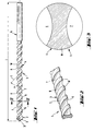
- FIGS. 1 to 3 An embodiment of the rotary drilling tool according to the invention is shown overall and in detail in FIGS. 1 to 3.
- this is a so-called twist drill for the axial impact-assisted extraction of rock or of reinforced base, in particular reinforced concrete, which is provided with the reference number 1 as a whole.
- the twist drill 1 At its front end, the twist drill 1 comprises a drill head 2, which is shown on the left in FIG. 1.
- the drill head 2 is equipped with main cutting edges 31, which are preferably formed on a hard metal cutting plate 3, which is soldered into the front end of the twist drill 1.
- a helical region 4 Connected to the drill head 2 is a helical region 4, which is formed by helices W, which delimit flutes 6, 7, which, starting from both sides of the flat sides of the hard metal plate, extend over part of the total length 1 of the helical drill 1 and are diametrically opposed to one another.
- an insertion end 5 Connected to the helical area 4 is an insertion end 5, which can be inserted into a drill chuck of a hammer drill, not shown, and with coupling interfaces for the transmission of a torque Is provided. The axial strokes are introduced into the tool via the rear end of the twist drill.
- the helices W are formed at least in a partial region of their longitudinal extent in such a way that their mass increases in the direction of their circumference starting from the axis A of the helical drill 1. In this case, approximately 50% to approximately 75% of the mass of the helices W are preferably arranged in their outer edge region.
- the coils W can be designed according to the invention over the entire coil region 4.
- only a partial area of its longitudinal extent can be provided with spirals W designed according to the invention.
- the drill head 2 is first connected by helices which are designed with regard to the optimal transport of the longitudinal wave, satisfactory transport of drilling dust and low sound radiation.
- the filaments W according to the invention the mass of which increases from the axis A of the twist drill to the circumference of the filaments W.
- the insertion end 5 finally connects to this area.
- the partial area having the inventive filaments W is connected, for example by friction welding, to the area carrying the conveying filament and the insertion end 5, and preferably has a larger diameter than the other areas of the twist drill.
- angles ⁇ which include the inclinations of the coils W according to the invention with the axis A of the twist drill 1, are preferably approximately 5 ° to approximately 50 °.
- the length of the helical area 4 is preferably about half to about two thirds of the total length 1 of the twist drill.
- the helical drill 1 according to the invention can, as illustrated by the preferred embodiment, have two flutes 6, 7 delimited by helices. However, several flutes could also be provided.
- the helices W delimiting the flutes 6, 7 lie diametrically opposite one another and have the same helix inclination S. It proves to be advantageous if the coils W have a symmetrical cross section.
- the drill head 2 at the front end of the twist drill 1 is in particular a rock drill head, the main cutting edges 31 of which include a negative rake angle with the axis A of the twist drill 1. Due to the roof-like design of the cutting edges, the forces occurring on the cutting edges due to the axial runout are better distributed and premature wear of the cutting edges can be prevented.
- the inventive design of the helixes induces a torsion wave from the longitudinal wave in the tool.
- the main cutting edges of the drill head of the rotary drilling tool not only experience a longitudinal impact but also a torsional impact in the direction of the force of the main cutting edges.
- the abrupt support of the force effect on the main cutting edges by the torsion impact increases the shearing effect on the main cutting edges, so that reinforcing bars can also be broken down by shearing.
- the longitudinal wave and the torsion wave arrive at the main cutting edges at the same time. Their superimposition creates a twist, which is far more energy-efficient, since it has an impact component in the direction of advance as well as in the tangential direction.
Landscapes
- Engineering & Computer Science (AREA)
- Geology (AREA)
- Life Sciences & Earth Sciences (AREA)
- Mining & Mineral Resources (AREA)
- Physics & Mathematics (AREA)
- Environmental & Geological Engineering (AREA)
- Fluid Mechanics (AREA)
- Mechanical Engineering (AREA)
- General Life Sciences & Earth Sciences (AREA)
- Geochemistry & Mineralogy (AREA)
- Processing Of Stones Or Stones Resemblance Materials (AREA)
- Earth Drilling (AREA)
- Percussive Tools And Related Accessories (AREA)
Applications Claiming Priority (2)
| Application Number | Priority Date | Filing Date | Title |
|---|---|---|---|
| DE1995104466 DE19504466A1 (de) | 1995-02-10 | 1995-02-10 | Drehbohrwerkzeug |
| DE19504466 | 1995-02-10 |
Publications (2)
| Publication Number | Publication Date |
|---|---|
| EP0726382A2 true EP0726382A2 (fr) | 1996-08-14 |
| EP0726382A3 EP0726382A3 (fr) | 1996-11-06 |
Family
ID=7753653
Family Applications (1)
| Application Number | Title | Priority Date | Filing Date |
|---|---|---|---|
| EP96810018A Withdrawn EP0726382A3 (fr) | 1995-02-10 | 1996-01-09 | Outil de forage rotatif |
Country Status (4)
| Country | Link |
|---|---|
| EP (1) | EP0726382A3 (fr) |
| JP (1) | JPH08238618A (fr) |
| CN (1) | CN1135957A (fr) |
| DE (1) | DE19504466A1 (fr) |
Cited By (2)
| Publication number | Priority date | Publication date | Assignee | Title |
|---|---|---|---|---|
| CN103600334A (zh) * | 2013-12-04 | 2014-02-26 | 湖南科技大学 | 等波阻钻头 |
| CN107152242A (zh) * | 2017-06-23 | 2017-09-12 | 浙江君悦标准件有限公司 | 一种导屑型钻孔螺杆 |
Families Citing this family (1)
| Publication number | Priority date | Publication date | Assignee | Title |
|---|---|---|---|---|
| DE102020208607A1 (de) * | 2020-07-09 | 2022-01-13 | Robert Bosch Gesellschaft mit beschränkter Haftung | Einsatzwerkzeug |
Family Cites Families (2)
| Publication number | Priority date | Publication date | Assignee | Title |
|---|---|---|---|---|
| DE2013328B1 (de) * | 1970-03-20 | 1971-07-15 | Werkzeugbau Gmbh, 8130 Starnberg | Gesteinsbohrer |
| DE4028261A1 (de) * | 1990-08-06 | 1992-02-13 | Fischer Artur Werke Gmbh | Bohrer zur herstellung von zylindrischen bohrloechern |
-
1995
- 1995-02-10 DE DE1995104466 patent/DE19504466A1/de not_active Withdrawn
-
1996
- 1996-01-09 EP EP96810018A patent/EP0726382A3/fr not_active Withdrawn
- 1996-02-08 CN CN 96101383 patent/CN1135957A/zh active Pending
- 1996-02-13 JP JP2530996A patent/JPH08238618A/ja active Pending
Cited By (4)
| Publication number | Priority date | Publication date | Assignee | Title |
|---|---|---|---|---|
| CN103600334A (zh) * | 2013-12-04 | 2014-02-26 | 湖南科技大学 | 等波阻钻头 |
| CN103600334B (zh) * | 2013-12-04 | 2016-06-22 | 湖南科技大学 | 等波阻钻头 |
| CN107152242A (zh) * | 2017-06-23 | 2017-09-12 | 浙江君悦标准件有限公司 | 一种导屑型钻孔螺杆 |
| CN107152242B (zh) * | 2017-06-23 | 2023-10-20 | 浙江君悦标准件有限公司 | 一种导屑型钻孔螺杆 |
Also Published As
| Publication number | Publication date |
|---|---|
| EP0726382A3 (fr) | 1996-11-06 |
| JPH08238618A (ja) | 1996-09-17 |
| CN1135957A (zh) | 1996-11-20 |
| DE19504466A1 (de) | 1996-08-14 |
Similar Documents
| Publication | Publication Date | Title |
|---|---|---|
| EP1273372B1 (fr) | Foret pour maçonnerie | |
| EP1125664B1 (fr) | Outil de forage pour pierre | |
| DE3317989C2 (fr) | ||
| EP0778391B1 (fr) | Perceuse rotative hélicoidale à percussion | |
| EP0884448B1 (fr) | Trépan de roche avec rainures d'évacuation hélicoidales | |
| EP0878261B1 (fr) | Outil de forage | |
| EP0657617A1 (fr) | Trépan de roche | |
| EP1259699B1 (fr) | Perforatrice de roches | |
| EP0778100B1 (fr) | Foret héliocoidal de percussion | |
| DE3407427A1 (de) | Bohrkrone | |
| EP1316669B1 (fr) | Outil de forage pour roche | |
| DE19807609A1 (de) | Spiralbohrer | |
| EP1197630B1 (fr) | Foret pour maçonnerie | |
| DE3743817C2 (de) | Gesteins-, Bohr- und Meisselwerkzeug | |
| EP2047932A2 (fr) | Foret | |
| DE3020284A1 (de) | Wendelbohrer | |
| EP3334945B1 (fr) | Procede de pose d'une vis | |
| DE19709771B4 (de) | Gesteinsbohrer | |
| EP1340604A2 (fr) | Foret | |
| DE19504466A1 (de) | Drehbohrwerkzeug | |
| DE102009023299B4 (de) | Bohrer | |
| EP1188897B1 (fr) | Trépan de forage de roche | |
| EP3263254A1 (fr) | Tête de forage | |
| DE2159728A1 (de) | Hammerbohrer | |
| DE10031968A1 (de) | Bohrer für Gestein |
Legal Events
| Date | Code | Title | Description |
|---|---|---|---|
| PUAI | Public reference made under article 153(3) epc to a published international application that has entered the european phase |
Free format text: ORIGINAL CODE: 0009012 |
|
| AK | Designated contracting states |
Kind code of ref document: A2 Designated state(s): CH DE DK FR GB LI SE |
|
| PUAL | Search report despatched |
Free format text: ORIGINAL CODE: 0009013 |
|
| AK | Designated contracting states |
Kind code of ref document: A3 Designated state(s): CH DE DK FR GB LI SE |
|
| 17P | Request for examination filed |
Effective date: 19961121 |
|
| 17Q | First examination report despatched |
Effective date: 20010504 |
|
| STAA | Information on the status of an ep patent application or granted ep patent |
Free format text: STATUS: THE APPLICATION IS DEEMED TO BE WITHDRAWN |
|
| 18D | Application deemed to be withdrawn |
Effective date: 20010801 |