EP0726420B1 - Armature lumineuse, en particulier pour locaux humides, à boítier fermé en deux parties - Google Patents
Armature lumineuse, en particulier pour locaux humides, à boítier fermé en deux parties Download PDFInfo
- Publication number
- EP0726420B1 EP0726420B1 EP96101915A EP96101915A EP0726420B1 EP 0726420 B1 EP0726420 B1 EP 0726420B1 EP 96101915 A EP96101915 A EP 96101915A EP 96101915 A EP96101915 A EP 96101915A EP 0726420 B1 EP0726420 B1 EP 0726420B1
- Authority
- EP
- European Patent Office
- Prior art keywords
- base part
- reflector
- housing base
- housing
- cover
- Prior art date
- Legal status (The legal status is an assumption and is not a legal conclusion. Google has not performed a legal analysis and makes no representation as to the accuracy of the status listed.)
- Expired - Lifetime
Links
- 239000000463 material Substances 0.000 claims abstract description 10
- 239000004033 plastic Substances 0.000 claims abstract description 9
- 229920003023 plastic Polymers 0.000 claims abstract description 9
- 239000004417 polycarbonate Substances 0.000 claims abstract description 4
- 229920000515 polycarbonate Polymers 0.000 claims abstract description 4
- 239000011521 glass Substances 0.000 claims description 3
- 239000002184 metal Substances 0.000 claims description 2
- 238000002347 injection Methods 0.000 claims 1
- 239000007924 injection Substances 0.000 claims 1
- 239000002991 molded plastic Substances 0.000 claims 1
- 239000000126 substance Substances 0.000 claims 1
- 238000001746 injection moulding Methods 0.000 abstract description 2
- 239000012780 transparent material Substances 0.000 description 4
- 230000000694 effects Effects 0.000 description 3
- 238000007789 sealing Methods 0.000 description 3
- 238000005286 illumination Methods 0.000 description 2
- 238000004519 manufacturing process Methods 0.000 description 2
- IHQKEDIOMGYHEB-UHFFFAOYSA-M sodium dimethylarsinate Chemical class [Na+].C[As](C)([O-])=O IHQKEDIOMGYHEB-UHFFFAOYSA-M 0.000 description 2
- 230000006641 stabilisation Effects 0.000 description 2
- 238000011105 stabilization Methods 0.000 description 2
- 210000002105 tongue Anatomy 0.000 description 2
- 239000003990 capacitor Substances 0.000 description 1
- 238000010276 construction Methods 0.000 description 1
- 239000000356 contaminant Substances 0.000 description 1
- 238000006073 displacement reaction Methods 0.000 description 1
- 239000000428 dust Substances 0.000 description 1
- 238000005265 energy consumption Methods 0.000 description 1
- 238000005516 engineering process Methods 0.000 description 1
- 230000003760 hair shine Effects 0.000 description 1
- 239000007921 spray Substances 0.000 description 1
- 239000007858 starting material Substances 0.000 description 1
- 238000010792 warming Methods 0.000 description 1
- XLYOFNOQVPJJNP-UHFFFAOYSA-N water Substances O XLYOFNOQVPJJNP-UHFFFAOYSA-N 0.000 description 1
Images


Classifications
-
- F—MECHANICAL ENGINEERING; LIGHTING; HEATING; WEAPONS; BLASTING
- F21—LIGHTING
- F21V—FUNCTIONAL FEATURES OR DETAILS OF LIGHTING DEVICES OR SYSTEMS THEREOF; STRUCTURAL COMBINATIONS OF LIGHTING DEVICES WITH OTHER ARTICLES, NOT OTHERWISE PROVIDED FOR
- F21V17/00—Fastening of component parts of lighting devices, e.g. shades, globes, refractors, reflectors, filters, screens, grids or protective cages
- F21V17/10—Fastening of component parts of lighting devices, e.g. shades, globes, refractors, reflectors, filters, screens, grids or protective cages characterised by specific fastening means or way of fastening
- F21V17/16—Fastening of component parts of lighting devices, e.g. shades, globes, refractors, reflectors, filters, screens, grids or protective cages characterised by specific fastening means or way of fastening by deformation of parts; Snap action mounting
- F21V17/164—Fastening of component parts of lighting devices, e.g. shades, globes, refractors, reflectors, filters, screens, grids or protective cages characterised by specific fastening means or way of fastening by deformation of parts; Snap action mounting the parts being subjected to bending, e.g. snap joints
-
- F—MECHANICAL ENGINEERING; LIGHTING; HEATING; WEAPONS; BLASTING
- F21—LIGHTING
- F21V—FUNCTIONAL FEATURES OR DETAILS OF LIGHTING DEVICES OR SYSTEMS THEREOF; STRUCTURAL COMBINATIONS OF LIGHTING DEVICES WITH OTHER ARTICLES, NOT OTHERWISE PROVIDED FOR
- F21V15/00—Protecting lighting devices from damage
- F21V15/01—Housings, e.g. material or assembling of housing parts
-
- F—MECHANICAL ENGINEERING; LIGHTING; HEATING; WEAPONS; BLASTING
- F21—LIGHTING
- F21V—FUNCTIONAL FEATURES OR DETAILS OF LIGHTING DEVICES OR SYSTEMS THEREOF; STRUCTURAL COMBINATIONS OF LIGHTING DEVICES WITH OTHER ARTICLES, NOT OTHERWISE PROVIDED FOR
- F21V17/00—Fastening of component parts of lighting devices, e.g. shades, globes, refractors, reflectors, filters, screens, grids or protective cages
- F21V17/10—Fastening of component parts of lighting devices, e.g. shades, globes, refractors, reflectors, filters, screens, grids or protective cages characterised by specific fastening means or way of fastening
- F21V17/107—Fastening of component parts of lighting devices, e.g. shades, globes, refractors, reflectors, filters, screens, grids or protective cages characterised by specific fastening means or way of fastening using hinge joints
-
- F—MECHANICAL ENGINEERING; LIGHTING; HEATING; WEAPONS; BLASTING
- F21—LIGHTING
- F21V—FUNCTIONAL FEATURES OR DETAILS OF LIGHTING DEVICES OR SYSTEMS THEREOF; STRUCTURAL COMBINATIONS OF LIGHTING DEVICES WITH OTHER ARTICLES, NOT OTHERWISE PROVIDED FOR
- F21V7/00—Reflectors for light sources
- F21V7/0008—Reflectors for light sources providing for indirect lighting
- F21V7/0016—Reflectors for light sources providing for indirect lighting on lighting devices that also provide for direct lighting, e.g. by means of independent light sources, by splitting of the light beam, by switching between both lighting modes
-
- F—MECHANICAL ENGINEERING; LIGHTING; HEATING; WEAPONS; BLASTING
- F21—LIGHTING
- F21V—FUNCTIONAL FEATURES OR DETAILS OF LIGHTING DEVICES OR SYSTEMS THEREOF; STRUCTURAL COMBINATIONS OF LIGHTING DEVICES WITH OTHER ARTICLES, NOT OTHERWISE PROVIDED FOR
- F21V11/00—Screens not covered by groups F21V1/00, F21V3/00, F21V7/00 or F21V9/00
- F21V11/08—Screens not covered by groups F21V1/00, F21V3/00, F21V7/00 or F21V9/00 using diaphragms containing one or more apertures
- F21V11/14—Screens not covered by groups F21V1/00, F21V3/00, F21V7/00 or F21V9/00 using diaphragms containing one or more apertures with many small apertures
-
- F—MECHANICAL ENGINEERING; LIGHTING; HEATING; WEAPONS; BLASTING
- F21—LIGHTING
- F21V—FUNCTIONAL FEATURES OR DETAILS OF LIGHTING DEVICES OR SYSTEMS THEREOF; STRUCTURAL COMBINATIONS OF LIGHTING DEVICES WITH OTHER ARTICLES, NOT OTHERWISE PROVIDED FOR
- F21V27/00—Cable-stowing arrangements structurally associated with lighting devices, e.g. reels
- F21V27/02—Cable inlets
-
- F—MECHANICAL ENGINEERING; LIGHTING; HEATING; WEAPONS; BLASTING
- F21—LIGHTING
- F21Y—INDEXING SCHEME ASSOCIATED WITH SUBCLASSES F21K, F21L, F21S and F21V, RELATING TO THE FORM OR THE KIND OF THE LIGHT SOURCES OR OF THE COLOUR OF THE LIGHT EMITTED
- F21Y2103/00—Elongate light sources, e.g. fluorescent tubes
-
- F—MECHANICAL ENGINEERING; LIGHTING; HEATING; WEAPONS; BLASTING
- F21—LIGHTING
- F21Y—INDEXING SCHEME ASSOCIATED WITH SUBCLASSES F21K, F21L, F21S and F21V, RELATING TO THE FORM OR THE KIND OF THE LIGHT SOURCES OR OF THE COLOUR OF THE LIGHT EMITTED
- F21Y2113/00—Combination of light sources
Definitions
- the lighting of a room can be of practical and / or aesthetic reasons Be meaningful. When lighting one for the stay of people furnished space, both of the aforementioned reasons may be relevant. With lights for subordinate rooms, e.g. Basement rooms or simple work rooms, is in the in most cases the requirement for good lighting of the space in the area of the workplace or the floor of the room. In contrast, when it comes to lighting Living rooms or representative rooms, e.g. Reception rooms, too on the aesthetic effect of the lighting.
- Both directly and indirectly effective lights have become known which the lighting of the room indirectly through a boundary surface of the room takes place, e.g. a ceiling or a wall.
- a luminaire for a subordinate room e.g. a basement or a simple work space
- a luminaire for a subordinate room e.g. a basement or a simple work space
- the latter applies especially for wet rooms, which in many cases are to be regarded as subordinate rooms are, and for which a good one with mainly low energy consumption Illumination of the room should be achieved.
- lights that provide both direct and indirect lighting for the Enable space. Such lights do not have a closed housing, e.g. only one screen open at the top, so that the direct lighting through the Light emission cone downwards and the indirect lighting upwards through the in Screen arranged opening takes place.
- Such and other lights with an unclosed housing are for in particular architecturally sophisticated rooms with a humid atmosphere not suitable, as a closed housing should be available in these rooms, to protect the at least one lamp of the lamp and to prevent others from getting moisture and contaminants e.g. Dust in that Housing can get into it.
- a luminaire for direct and indirect lighting is a Described space of a building or the like.
- a reflector provided with many holes, above which to an upper Main light exit opening of the light directed reflective top at least one lamp is arranged.
- At the bottom of the case is another lower light exit opening with a transparent, diffuse light bottom cover in place.
- this known lamp there is only a small proportion of the useful light emitted by the at least one lamp of this lamp the lower light outlet can be emitted through.
- the invention has for its object a lamp of the type specified To be designed so that the lighting of the room is improved.
- the light not only occurs in the area of the cover from, but it also emerges in the region of the trough-shaped housing base part, wherein the latter part of the light to illuminate a ceiling or wall carrying the lamp is able to make the entire room appear brighter.
- the lamp according to the invention is preferably suitable for rooms in which a closed housing (housing with a higher degree of protection) is prescribed, such as described damp rooms, e.g. Work rooms, garages and the like. At In such rooms, the lighting needs to be improved.
- the Invention an improved lighting of the existing space since the space is not is only illuminated towards the side on which the cover is located, but the Space is also illuminated towards the side facing away from the cover, one associated ceiling or wall due to their lighting the light additionally reflects back what leads to the previously described illumination of the room as a whole and leads in particular in the area of the ceiling or wall carrying the lamp.
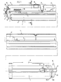
- the main parts of the lamp 1 are a closed housing 2, one or more therein arranged sockets 3 with electrical contacts for one or more lamps, in particular fluorescent tubes 4 and a reflector 5, which is in a roof-shaped shape and position above the lamp or lamps in the housing 2, which in the Present embodiment elongated housing 2 with a housing base part 6 and a cover 7 is formed in two parts and that of the cover 7 closed opening is designated 8. Between the housing base part 6 and the Cover 7 are two or more, four in the present embodiment Quick fasteners 9 on the broad sides of the elongated housing 2 each other arranged opposite on the outside.
- the housing base part 6 has a on its side facing away from the cover 7 Base or at least two of the housing base part 6 preferably upwards protruding, e.g. strip-shaped feet 10 in the area or between them Through holes are provided for attachment by means of insertable from the inside Screws (not shown) on a ceiling or wall.
- the width a of the feet is dimensioned smaller than the associated width b of the housing 2. This results in on both sides of the housing 2, preferably in the end regions of the elongated housing 2 arranged feet 10 divergent wall sections 11 that extend to the horizontal Extension 12 extend between the housing base part 6 and the cover 7.
- the feet 10 are on the top of one on the head standing box 13 arranged in the longitudinal direction of the elongated Housing 2 extends centrally and the top wall with 14, the side walls with 15 and the end walls are designated 16.
- the divergent wall sections 11 are Sections of a semi-circular shape of the housing base part 6 in vertical section, to which the shape of the cover 7 connects, so that the latter one accordingly has large sized semicircular bottom wall 17.
- Box 13 is on both
- the ends of the elongated housing 2 are dimensioned somewhat longer than the divergent ones Wall sections 11 so that it projects over the latter with its side walls 15, and this in the extension area up to the middle division area of the housing 2 extend.
- the cover 7 has a tapered one Step 19 with a staggered annular end wall 21 and the actual one End wall 22 on.
- the cover 7 has a circumferential vertical web wall 23, which in a circumferential channel 24 protrudes in the form of an upside down U.
- the height of the web wall 23 and the channel 24 is approximately 15 to 20 mm.
- This is a Maze created that the housing 2 against moisture and water spray seals.
- a second, circumferential groove 25 in the shape of an upside-down U. provided, from the groove bottom, the web wall 23 extends upwards.
- At 26 is a tight cable entry with an elastic grommet in one Hole of the housing wall, here the end wall 16.
- quick-release fasteners 9 are provided for fastening the cover 7 to the housing base part 6 provided that each other on the broad sides of the housing 2 in its end region are arranged opposite one another.
- the quick fasteners 9 are preferably through mutually identical C-shaped clips 27 formed with a pin-shaped
- the clasp base part 28 is seated in the lower groove 25, preferably being clamped therein are held, and the upper claw-shaped closure ends 29 of the bottom 24b of the overlap upper gutter 24 with a clamping effect.
- the Sockets 3 with socket pieces 3a extending from top to bottom in the lower one Area of the housing 2, i.e. in the area of the cover 7.
- the reflector 5 is arranged and held in the housing 2 at present embodiment in the area of the division 12.
- the reflector 5 is an im essentially flat body, preferably made of sheet metal, which in the present case Design by a profile shape extending in its longitudinal direction is stabilized, in the present embodiment by the end, upwards directed bend 32 and preferably also a central, upward directed step 33, the free edges of the angled legs 32nd can be bent in a channel shape downwards.
- the width c of the reflector 5 is on adjusted the inner width d between the channel 24.
- the two holders 34 are provided on the housing base part 6, which the reflector 5 of reach under at the top.
- the two holders 34 are preferably in the central region of the provided both longitudinal halves. In the present embodiment, they are each other same or mirror-inverted holder 34 by horizontal deflectable latch arms 35 which extend from top to bottom, the Grasp reflector 5 in an associated hole 36 and with a locking lug 37 reach under the edge of the hole with bevels 38.
- two latch arms 35 Preferably at each of the described two mounting points two latch arms 35 with respect to vertical longitudinal center plane 39 arranged opposite one another.
- the locking arms 35 are each on a preferably box-shaped Bracket base 41 formed, which is in the sense of a retraction from the ceiling wall 14 extends downward.
- On the latch arms 35 can with respect to Longitudinal center plane 39 laterally projecting hook members 42, which are in the Reflector 5 lateral attachment holes 43 are assigned, and this makes it possible the reflector 5 on an optional side in a downward tilted position attach the associated hook members 42.
- Housing base part 6 accessible from below so that work can be carried out therein can, e.g. Wiring, testing or replacement on a starter 44 or a ballast 45 can be performed without the reflector 5 of the Lamp 1 or from the housing base part 6 must be completely removed.
- the reflector 5 it is advantageous for the reflector 5 to have additional lateral abutments 46 on Assign housing base part 6, which in the present embodiment by downward ends or recesses formed by vertical recesses 47 can be against which the side edges of the reflector 31 abut or from below mounting.
- the hole edges of the holes 36 can be stepped upwards Be pronounced.
- the socket pieces 3a can be on the underside and the ballast 45 and any associated terminals 48 on the top Be attached reflector 5 (see Figures 1 and 4).
- the reference number 51 is punched out and bent out of the reflector Tongues provided at longitudinal distances from each other, which the bracket by clamping of wires of the associated electrical lines.
- a corresponding one Cut-out and bent-out tongue 52 does not serve to hold one further shown capacitor.
- the cover 7 consists at least in the lamp or fluorescent tube 4 opposite area made of a translucent or transparent material like plastic or glass.
- a translucent or transparent material like plastic or glass.
- one is unbreakable Plastic provided, e.g. Polycarbonate.
- Cover 7 preferably exists altogether from one of the aforementioned materials. This is not just a big one Spread area for the light available, but the cover 7 can also as a one-piece component, in particular plastic injection molding, simply and inexpensively manufacture.
- the reflector 5 is on at least a portion of its surface Translucent, there are several design options.
- the Reflector 5 can be translucent or in part or in total be translucent. In the former case, the reflector 5 can be in the at least one Area or all consist of translucent or transparent material. In the second case, the reflector 5 can consist of opaque material and in in the at least one area have holes 53, in the area of which the light is not is reflected, but radiates through the holes 53 into the housing base part 6.
- the housing base part 6 also consists of at least one area at least partially translucent or transparent material, this Area in the direction of propagation of the rays behind the at least one translucent or partially translucent area of the reflector 5.
- the area or areas described above may be within the scope of the invention e.g. act around the central region e of the reflector 5.
- Translucent areas f in the reflector 5 can also on both sides of the above-described area e.
- the reflector 5 is preferably on its entire surface is translucent or partially translucent.
- the reflector 5 has holes 53 over its entire surface, wherein its remaining lower surface is designed to be light-reflecting, in particular coated, so that part of the light rays is reflected towards the cover 7 and part of the Light rays radiate into the housing base part 6.
- Such a reflector is preferably 5th made from a perforated plate prefabricated with holes 53.
- Figure 4 shows For reasons of simplification, only a partial area of the entire width and length Reflector 5 having holes 53.
- the housing base part 6 preferably the housing base part 6 as a whole, made of translucent or transparent material such as glass or in particular plastic, preferably unbreakable plastic like polycarbonate. It is particularly advantageous that To produce the housing base part 6 from the same material from which the cover 7th consists. Not only is this easier in terms of production technology, but it also becomes one achieved higher or secure sealing because the housing base part 6 and Cover 7 have the same coefficient of thermal expansion and therefore at Warming up during operation of the lamp 1 Warping, tension and displacements are avoided.
- part of the light rays namely that in the Housing base part 6 radiating light rays radiated to the side of the lamp 1, on which the housing base part 6 is located, specifically against the one carrying the lamp 1 Component, usually a ceiling or a wall.
- a ceiling or a wall usually a ceiling or a wall.
- the lamp 1 according to the invention is particularly suitable for a damp room lamp and thus for damp, dusty and also subordinate rooms, because especially those Rooms need better lighting, and not just in the luminaire load-bearing ceiling or wall area, but also overall.
- the embodiment of Figure 5 differs from the above Embodiment essentially only in that the lamp is dimensioned wider and several lamps or fluorescent tubes 4, preferably two, with associated sockets (3) are arranged side by side.
- the two can arcuate side areas of the cover 7 in the central area of the Luminaire to be connected to each other by a secant bottom section 17a.
Landscapes
- Engineering & Computer Science (AREA)
- General Engineering & Computer Science (AREA)
- Non-Portable Lighting Devices Or Systems Thereof (AREA)
- Arrangement Of Elements, Cooling, Sealing, Or The Like Of Lighting Devices (AREA)
- Fastening Of Light Sources Or Lamp Holders (AREA)
Claims (10)
- Luminaire (1) comprenant un boítier (2) fermé, en deux parties, dans lequel sont disposées une ou plusieurs douilles (3) pour au moins une ou plusieurs lampes, en particulier des tubes fluorescents (4), le boítier (2) comprenant une partie de base (6) en forme d'auge et un paralume (7) constitué au moins sur une zone partielle par un matériau perméable à la lumière et fixé à l'aide d'éléments de fixation de façon amovible à la partie de base (6), un réflecteur (5) étant disposé et maintenu dans le boítier (2), la paroi de la partie de base (6) étant constituée, sur une zone partielle au moins, également par un matériau perméable à la lumière, et le réflecteur (5) s'étendant entre la lampe et la partie de base (6) et étant, sur une zone partielle au moins, partiellement perméable à la lumière.
- Luminaire suivant la revendication 1, caractérisé par le fait que la paroi de la partie de base (6) et la paroi du paralume (7) sont constituées par le même matériau.
- Luminaire suivant la revendication 1 ou 2, caractérisé par le fait que la paroi de la partie de base (6) et/ou la paroi du paralume (7) est (sont) constituée(s) par de la matière plastique, en particulier une matière plastique incassable, de préférence du polycarbonate.
- Luminaire suivant la revendication 3, caractérisé par le fait que la partie de base (6) et/ou le paralume (7) est (sont) constitué(s) essentiellement en entier d'une seule pièce en matériau perméable à la lumière et sont de préférence des pièces moulées par injection en matière plastique.
- Luminaire suivant l'une des revendications précédentes, caractérisé par le fait que le réflecteur (5) est en verre ou en matière plastique.
- Luminaire suivant l'une des revendications précédentes, caractérisé par le fait que le réflecteur (5) présente des trous (53) dans au moins une zone (e, f) partiellement perméable à la lumière.
- Luminaire suivant la revendication 6, caractérisé par le fait que le réflecteur (5) présente des trous (53) dans toute sa zone.
- Luminaire suivant la revendication 7, caractérisé par le fait que le réflecteur (5) est constitué par une tôle perforée.
- Luminaire suivant l'une des revendications précédentes, caractérisé par le fait que la partie de base (6) présente des sections de parois latérales (11) qui s'étendent en divergeant vers le paralume (7).
- Luminaire suivant la revendication 9, caractérisé par le fait que les sections de parois divergentes (11) partent d'une partie d'embase (15, 16) en forme de caisson de la partie de base (6).
Applications Claiming Priority (2)
| Application Number | Priority Date | Filing Date | Title |
|---|---|---|---|
| DE29502183U DE29502183U1 (de) | 1995-02-10 | 1995-02-10 | Leuchte, insbesondere Feuchtraumleuchte, mit einem zweiteiligen geschlossenen Gehäuse |
| DE29502183U | 1995-02-10 |
Publications (2)
| Publication Number | Publication Date |
|---|---|
| EP0726420A1 EP0726420A1 (fr) | 1996-08-14 |
| EP0726420B1 true EP0726420B1 (fr) | 2000-07-05 |
Family
ID=8003722
Family Applications (1)
| Application Number | Title | Priority Date | Filing Date |
|---|---|---|---|
| EP96101915A Expired - Lifetime EP0726420B1 (fr) | 1995-02-10 | 1996-02-09 | Armature lumineuse, en particulier pour locaux humides, à boítier fermé en deux parties |
Country Status (4)
| Country | Link |
|---|---|
| EP (1) | EP0726420B1 (fr) |
| AT (1) | ATE194420T1 (fr) |
| DE (2) | DE29502183U1 (fr) |
| ES (1) | ES2150028T3 (fr) |
Cited By (2)
| Publication number | Priority date | Publication date | Assignee | Title |
|---|---|---|---|---|
| WO2004020900A1 (fr) | 2002-08-09 | 2004-03-11 | A. Raymond & Cie | Plafonnier comprenant un boitier allonge |
| DE202023100154U1 (de) | 2023-01-13 | 2024-04-16 | Tridonic Gmbh & Co Kg | Halteadapter zur Nachrüstung von Feuchtraumleuchten |
Families Citing this family (9)
| Publication number | Priority date | Publication date | Assignee | Title |
|---|---|---|---|---|
| DE19814383A1 (de) * | 1998-03-31 | 1999-10-14 | Siteco Beleuchtungstech Gmbh | Feuchtraumleuchte |
| EP1052452B1 (fr) * | 1999-05-11 | 2007-10-10 | Koninklijke Philips Electronics N.V. | Luminaire de forme allongée |
| EP1052454B1 (fr) * | 1999-05-11 | 2007-10-24 | Koninklijke Philips Electronics N.V. | Luminaire d'intérieur/industriel |
| DE10134795B4 (de) * | 2001-07-11 | 2012-03-29 | Reiss Lighting Gmbh | Leuchte |
| DE102004044167A1 (de) * | 2004-09-13 | 2006-04-06 | BöSha GmbH + Co KG | Transparente Abdeckungen für explosionsgeschützte Leuchten |
| DE102005058961A1 (de) † | 2005-12-09 | 2007-06-14 | Zumtobel Lighting Gmbh | Leuchte mit einer in ihrem Hohlraum gehaltenen Tragplatte |
| ATE448443T1 (de) | 2007-09-11 | 2009-11-15 | Flowil Int Lighting | Druckbefestigungsclip |
| ATE539297T1 (de) | 2007-11-09 | 2012-01-15 | Siteco Beleuchtungstech Gmbh | Wannenleuchte mit indirektanteil des lichts |
| DE102013018549A1 (de) * | 2013-11-05 | 2015-05-07 | Siteco Beleuchtungstechnik Gmbh | Beleuchtungsvorrichtung |
Family Cites Families (11)
| Publication number | Priority date | Publication date | Assignee | Title |
|---|---|---|---|---|
| DE1073627B (de) * | 1960-01-21 | Siemens-Schuckertwerke Aktiengesellschaft, Berlin Und Erlangen | Abgedichtete Leuchte für Leuchtstofflampen | |
| GB541505A (en) * | 1940-10-24 | 1941-11-28 | Gen Electric Co Ltd | Improvements in street-lighting fittings |
| GB955877A (en) * | 1961-08-21 | 1964-04-22 | Ass Elect Ind | Improvements in electric illumination systems employing electric discharge lamps |
| BE758829A (fr) * | 1969-11-12 | 1971-04-16 | Elektro Mibo A B | Perfectionnements aux appareils d'eclairage |
| US4282564A (en) * | 1978-07-24 | 1981-08-04 | Mcjunkin Corporation | Triangular enclosure for tubular light source |
| DE3442527A1 (de) * | 1983-11-23 | 1985-05-30 | Bösha GmbH & Co KG, 4780 Lippstadt | Langfeldleuchte fuer den einsatz in schlagwetter- und explosionsgeschuetzten bereichen |
| EP0217323A3 (fr) * | 1985-10-02 | 1989-03-08 | THORN LICHT GmbH | Dispositif et procédé d'éclairage |
| US4748547A (en) * | 1987-02-06 | 1988-05-31 | Baker Glenn A | Uplight luminaire for achieving uniform illuminance across a ceiling |
| FR2622677B1 (fr) * | 1987-11-04 | 1991-12-13 | Wattohm Eclairage | Appareil etanche d'eclairage a tubes fluorescents |
| DE4210444A1 (de) * | 1992-03-30 | 1993-10-07 | Hartmut S Engel | Strahler mit gestufter Reflektorfläche |
| DE9415376U1 (de) * | 1994-09-22 | 1994-11-10 | Staff GmbH & Co KG, 32657 Lemgo | Rinnenförmiger Spiegelreflektor für stabförmige Leuchtmittel |
-
1995
- 1995-02-10 DE DE29502183U patent/DE29502183U1/de not_active Expired - Lifetime
-
1996
- 1996-02-09 ES ES96101915T patent/ES2150028T3/es not_active Expired - Lifetime
- 1996-02-09 EP EP96101915A patent/EP0726420B1/fr not_active Expired - Lifetime
- 1996-02-09 DE DE59605526T patent/DE59605526D1/de not_active Expired - Lifetime
- 1996-02-09 AT AT96101915T patent/ATE194420T1/de active
Cited By (3)
| Publication number | Priority date | Publication date | Assignee | Title |
|---|---|---|---|---|
| WO2004020900A1 (fr) | 2002-08-09 | 2004-03-11 | A. Raymond & Cie | Plafonnier comprenant un boitier allonge |
| DE202023100154U1 (de) | 2023-01-13 | 2024-04-16 | Tridonic Gmbh & Co Kg | Halteadapter zur Nachrüstung von Feuchtraumleuchten |
| EP4403823A1 (fr) | 2023-01-13 | 2024-07-24 | Tridonic GmbH & Co. KG | Adaptateur de support pour la rénovation de luminaires de locaux humides |
Also Published As
| Publication number | Publication date |
|---|---|
| DE29502183U1 (de) | 1996-05-02 |
| ES2150028T3 (es) | 2000-11-16 |
| EP0726420A1 (fr) | 1996-08-14 |
| DE59605526D1 (de) | 2000-08-10 |
| ATE194420T1 (de) | 2000-07-15 |
Similar Documents
| Publication | Publication Date | Title |
|---|---|---|
| EP1043542B2 (fr) | Système d' éclairage pour installation au plafond ou au mur d' une pièce | |
| DE3147510A1 (de) | Abgehaengte decke mit integriertem beleuchtungskoerper, beleuchtungskoerper und verfahren zum bau einer abgehaengten decke mit beleuchtungskoerper | |
| DE10151958A1 (de) | Leuchte mit mehreren Topfreflektoren | |
| EP1337786A2 (fr) | Lampe pourvue d'une vitre transparente | |
| EP0726420A1 (fr) | Armature lumineuse, en particulier pour locaux humides, à boîtier fermé en deux parties | |
| EP0716262A1 (fr) | Armature d'éclairage pour sources lumineuses linéaires | |
| DE19923224A1 (de) | Beleuchtungsanordnung zur Anbringung an der Decke oder einer Wand eines Raumes | |
| EP2824380B1 (fr) | Éclairage | |
| EP3414487B1 (fr) | Système de bande lumineuse à rail de support de forme allongée | |
| EP3366991A1 (fr) | Support d'appareil pour luminaire | |
| EP3366986B1 (fr) | Capot du luminaire et luminaire | |
| EP2258978B1 (fr) | Luminaire avec une glace de fermeture transparente | |
| DE20204352U1 (de) | Leuchte | |
| EP0222115B1 (fr) | Lampe de plafond | |
| EP0795719B1 (fr) | Unité modulaire pour illumination | |
| DE19721340A1 (de) | Leuchte | |
| DE4202768C2 (de) | Leuchte | |
| DE202008012492U1 (de) | Gehäuse einer Aussenbeleuchtung | |
| DE19531351C2 (de) | Leuchteneinheit für ein Lichtbandsystem | |
| DE10216761B4 (de) | Leuchte mit reibschlüssig befestigtem Leuchtenbauteil und zugehöriges Leuchtenbauteil | |
| DE19917432C2 (de) | Reflektorleuchte, die als Flächenfluter, insbesondere als Wand- oder Deckenfluter, ausgebildet ist | |
| DE20112365U1 (de) | Leuchte mit einem Basisteil und einer wannenförmigen Abdeckung sowie Basisteil für eine Leuchte | |
| DE202007013177U1 (de) | Leuchte | |
| DE4433862C1 (de) | Reflektor- und Abschirmsystem für eine Deckenleuchte | |
| EP0962692B1 (fr) | Luminaire avec un élément de protection contre les insectes |
Legal Events
| Date | Code | Title | Description |
|---|---|---|---|
| PUAI | Public reference made under article 153(3) epc to a published international application that has entered the european phase |
Free format text: ORIGINAL CODE: 0009012 |
|
| AK | Designated contracting states |
Kind code of ref document: A1 Designated state(s): AT BE CH DE ES FR GB IT LI NL |
|
| 17P | Request for examination filed |
Effective date: 19970212 |
|
| 17Q | First examination report despatched |
Effective date: 19990303 |
|
| GRAG | Despatch of communication of intention to grant |
Free format text: ORIGINAL CODE: EPIDOS AGRA |
|
| GRAG | Despatch of communication of intention to grant |
Free format text: ORIGINAL CODE: EPIDOS AGRA |
|
| GRAH | Despatch of communication of intention to grant a patent |
Free format text: ORIGINAL CODE: EPIDOS IGRA |
|
| GRAH | Despatch of communication of intention to grant a patent |
Free format text: ORIGINAL CODE: EPIDOS IGRA |
|
| RAP1 | Party data changed (applicant data changed or rights of an application transferred) |
Owner name: ZUMTOBEL STAFF GMBH |
|
| RIC1 | Information provided on ipc code assigned before grant |
Free format text: 7F 21S 8/04 A, 7F 21V 7/00 B |
|
| GRAA | (expected) grant |
Free format text: ORIGINAL CODE: 0009210 |
|
| AK | Designated contracting states |
Kind code of ref document: B1 Designated state(s): AT BE CH DE ES FR GB IT LI NL |
|
| REF | Corresponds to: |
Ref document number: 194420 Country of ref document: AT Date of ref document: 20000715 Kind code of ref document: T |
|
| REG | Reference to a national code |
Ref country code: CH Ref legal event code: NV Representative=s name: A. BRAUN, BRAUN, HERITIER, ESCHMANN AG PATENTANWAE Ref country code: CH Ref legal event code: EP |
|
| REF | Corresponds to: |
Ref document number: 59605526 Country of ref document: DE Date of ref document: 20000810 |
|
| GBT | Gb: translation of ep patent filed (gb section 77(6)(a)/1977) |
Effective date: 20000720 |
|
| ET | Fr: translation filed | ||
| ITF | It: translation for a ep patent filed | ||
| REG | Reference to a national code |
Ref country code: ES Ref legal event code: FG2A Ref document number: 2150028 Country of ref document: ES Kind code of ref document: T3 |
|
| PLBE | No opposition filed within time limit |
Free format text: ORIGINAL CODE: 0009261 |
|
| STAA | Information on the status of an ep patent application or granted ep patent |
Free format text: STATUS: NO OPPOSITION FILED WITHIN TIME LIMIT |
|
| 26N | No opposition filed | ||
| REG | Reference to a national code |
Ref country code: GB Ref legal event code: IF02 |
|
| REG | Reference to a national code |
Ref country code: CH Ref legal event code: PFA Owner name: ZUMTOBEL STAFF GMBH Free format text: ZUMTOBEL STAFF GMBH#SCHWEIZERSTRASSE 30#6850 DORNBIRN (AT) -TRANSFER TO- ZUMTOBEL STAFF GMBH#SCHWEIZERSTRASSE 30#6850 DORNBIRN (AT) |
|
| PGFP | Annual fee paid to national office [announced via postgrant information from national office to epo] |
Ref country code: ES Payment date: 20090225 Year of fee payment: 14 |
|
| PGFP | Annual fee paid to national office [announced via postgrant information from national office to epo] |
Ref country code: BE Payment date: 20090224 Year of fee payment: 14 |
|
| PGFP | Annual fee paid to national office [announced via postgrant information from national office to epo] |
Ref country code: FR Payment date: 20090217 Year of fee payment: 14 |
|
| BERE | Be: lapsed |
Owner name: *ZUMTOBEL STAFF G.M.B.H. Effective date: 20100228 |
|
| REG | Reference to a national code |
Ref country code: FR Ref legal event code: ST Effective date: 20101029 |
|
| PG25 | Lapsed in a contracting state [announced via postgrant information from national office to epo] |
Ref country code: FR Free format text: LAPSE BECAUSE OF NON-PAYMENT OF DUE FEES Effective date: 20100301 |
|
| PG25 | Lapsed in a contracting state [announced via postgrant information from national office to epo] |
Ref country code: BE Free format text: LAPSE BECAUSE OF NON-PAYMENT OF DUE FEES Effective date: 20100228 |
|
| REG | Reference to a national code |
Ref country code: ES Ref legal event code: FD2A Effective date: 20110330 |
|
| PG25 | Lapsed in a contracting state [announced via postgrant information from national office to epo] |
Ref country code: ES Free format text: LAPSE BECAUSE OF NON-PAYMENT OF DUE FEES Effective date: 20110317 |
|
| PG25 | Lapsed in a contracting state [announced via postgrant information from national office to epo] |
Ref country code: ES Free format text: LAPSE BECAUSE OF NON-PAYMENT OF DUE FEES Effective date: 20100210 |
|
| PGFP | Annual fee paid to national office [announced via postgrant information from national office to epo] |
Ref country code: CH Payment date: 20120228 Year of fee payment: 17 |
|
| PGFP | Annual fee paid to national office [announced via postgrant information from national office to epo] |
Ref country code: GB Payment date: 20120229 Year of fee payment: 17 Ref country code: IT Payment date: 20120222 Year of fee payment: 17 |
|
| PGFP | Annual fee paid to national office [announced via postgrant information from national office to epo] |
Ref country code: NL Payment date: 20120229 Year of fee payment: 17 Ref country code: DE Payment date: 20120430 Year of fee payment: 17 |
|
| PGFP | Annual fee paid to national office [announced via postgrant information from national office to epo] |
Ref country code: AT Payment date: 20120224 Year of fee payment: 17 |
|
| REG | Reference to a national code |
Ref country code: NL Ref legal event code: V1 Effective date: 20130901 |
|
| REG | Reference to a national code |
Ref country code: CH Ref legal event code: PL |
|
| REG | Reference to a national code |
Ref country code: AT Ref legal event code: MM01 Ref document number: 194420 Country of ref document: AT Kind code of ref document: T Effective date: 20130228 |
|
| GBPC | Gb: european patent ceased through non-payment of renewal fee |
Effective date: 20130209 |
|
| PG25 | Lapsed in a contracting state [announced via postgrant information from national office to epo] |
Ref country code: LI Free format text: LAPSE BECAUSE OF NON-PAYMENT OF DUE FEES Effective date: 20130228 Ref country code: NL Free format text: LAPSE BECAUSE OF NON-PAYMENT OF DUE FEES Effective date: 20130901 Ref country code: CH Free format text: LAPSE BECAUSE OF NON-PAYMENT OF DUE FEES Effective date: 20130228 Ref country code: AT Free format text: LAPSE BECAUSE OF NON-PAYMENT OF DUE FEES Effective date: 20130228 |
|
| REG | Reference to a national code |
Ref country code: DE Ref legal event code: R119 Ref document number: 59605526 Country of ref document: DE Effective date: 20130903 |
|
| PG25 | Lapsed in a contracting state [announced via postgrant information from national office to epo] |
Ref country code: IT Free format text: LAPSE BECAUSE OF NON-PAYMENT OF DUE FEES Effective date: 20130209 |
|
| PG25 | Lapsed in a contracting state [announced via postgrant information from national office to epo] |
Ref country code: DE Free format text: LAPSE BECAUSE OF NON-PAYMENT OF DUE FEES Effective date: 20130903 Ref country code: GB Free format text: LAPSE BECAUSE OF NON-PAYMENT OF DUE FEES Effective date: 20130209 |