EP0726445A2 - Procédé et dispositif pour mesurer le volume d'un objet en mouvement - Google Patents
Procédé et dispositif pour mesurer le volume d'un objet en mouvement Download PDFInfo
- Publication number
- EP0726445A2 EP0726445A2 EP96250013A EP96250013A EP0726445A2 EP 0726445 A2 EP0726445 A2 EP 0726445A2 EP 96250013 A EP96250013 A EP 96250013A EP 96250013 A EP96250013 A EP 96250013A EP 0726445 A2 EP0726445 A2 EP 0726445A2
- Authority
- EP
- European Patent Office
- Prior art keywords
- conveyed
- measuring
- distance
- medium
- sensors
- Prior art date
- Legal status (The legal status is an assumption and is not a legal conclusion. Google has not performed a legal analysis and makes no representation as to the accuracy of the status listed.)
- Withdrawn
Links
- 238000000034 method Methods 0.000 title claims description 15
- 238000005259 measurement Methods 0.000 claims abstract description 18
- 230000004888 barrier function Effects 0.000 claims description 12
- 230000003287 optical effect Effects 0.000 claims description 8
- 238000011156 evaluation Methods 0.000 claims description 6
- 238000000149 argon plasma sintering Methods 0.000 claims description 3
- 230000010363 phase shift Effects 0.000 claims description 3
- 230000002123 temporal effect Effects 0.000 claims description 3
- 230000010354 integration Effects 0.000 description 4
- 238000010586 diagram Methods 0.000 description 2
- 238000001228 spectrum Methods 0.000 description 2
- 235000010627 Phaseolus vulgaris Nutrition 0.000 description 1
- 244000046052 Phaseolus vulgaris Species 0.000 description 1
- TZCXTZWJZNENPQ-UHFFFAOYSA-L barium sulfate Chemical compound [Ba+2].[O-]S([O-])(=O)=O TZCXTZWJZNENPQ-UHFFFAOYSA-L 0.000 description 1
- 238000013016 damping Methods 0.000 description 1
- 238000006073 displacement reaction Methods 0.000 description 1
- 238000005516 engineering process Methods 0.000 description 1
- 238000005286 illumination Methods 0.000 description 1
- 230000001939 inductive effect Effects 0.000 description 1
Images



Classifications
-
- G—PHYSICS
- G01—MEASURING; TESTING
- G01B—MEASURING LENGTH, THICKNESS OR SIMILAR LINEAR DIMENSIONS; MEASURING ANGLES; MEASURING AREAS; MEASURING IRREGULARITIES OF SURFACES OR CONTOURS
- G01B17/00—Measuring arrangements characterised by the use of infrasonic, sonic or ultrasonic vibrations
-
- G—PHYSICS
- G01—MEASURING; TESTING
- G01B—MEASURING LENGTH, THICKNESS OR SIMILAR LINEAR DIMENSIONS; MEASURING ANGLES; MEASURING AREAS; MEASURING IRREGULARITIES OF SURFACES OR CONTOURS
- G01B11/00—Measuring arrangements characterised by the use of optical techniques
Definitions
- the invention relates to a method and a device for measuring the volume of a moving material to be conveyed, in particular the width and height of a piece of material to be conveyed, by scanning in at least two measuring directions, the measurement results of which are used to calculate the volume size.
- Known and applicable methods for conveying technology for measuring the volume of a moving material usually consist of a measuring frame with a "light barrier measuring grid".
- this light barrier measuring grid a large number of light barriers are arranged, on the one hand, horizontally and perpendicular to the conveying direction and, on the other hand, also vertically likewise perpendicular to the conveying direction. Damped light barriers horizontally, perpendicular to the conveying direction, give the height of the material to be conveyed, and the width of the conveyed material is determined from the vertical light barriers.
- the length of the material to be conveyed is calculated from the duration of the light barrier damping and the conveying speed.
- a sorting device for beans based on an optical sensor has already been proposed for agricultural products (DE 27 22 368.).
- the device includes a passageway through which the items to be sorted are passed using an illumination system connected to the passageway to produce a small, uniformly shaped layer of light that extends perpendicular to the passageway and has a light receiver that is also included is connected to the passageway, thereby generating light-based signals that are reflected by the objects that pass through this light layer.
- the light receiver receives non-directional reflected light and is able to transmit light of two different bandwidths To measure light spectrum. Both light bands lie within the visible or infrared part of the spectrum.
- the present invention is therefore based on the object of proposing a method and a device for measuring the volume of a conveyed material in which a low procedural and / or technical outlay is required and nevertheless a sufficiently precise measurement value determination or calculation of the volume can take place.
- the object is achieved according to the invention in that the distance from the conveyed item is measured from a reference point in such a way that the distance between the reference point and the respective one is at least parallel to the conveying plane with at least one first distance sensor and perpendicular to the conveying plane with at least one second distance sensor Surface of the material being conveyed is measured, the material being conveyed being held on a predetermined movement line by mechanical measures or a movement line being determined by measurements.
- this method manages with two measured values, measuring principles such as optical, acoustic, capacitive, inductive displacement measurements and the like. can be used.
- the associated length of the conveyed material is determined from the temporal length of the signals of the first and / or the second distance sensor.
- the length of the material to be conveyed is measured by a light barrier system surrounding the material to be conveyed on several sides and the associated attenuation of the measuring beams.
- the material to be measured cannot be held with sufficient accuracy on the determined movement line, so that an incline or the like. takes place proposed that the distance parallel to the medium level is measured by the second distance sensor and a third distance sensor, the second and third distance sensors working in opposite directions. In this case it is also possible to measure the delivery volume if the movement deviates from a desired reference line.
- a volume evaluation is carried out from the three measuring signals by a combined evaluation of at least two antiparallel to the conveying plane and a measuring beam directed vertically onto the conveying material or the conveying medium plane.
- a device for measuring the volume of a moving material to be conveyed, in particular the width and height of a piece of material to be conveyed, by scanning using measuring beams in at least two measuring directions, the measurement results being usable for calculating the volume size, is advantageously created by contactlessly outside of a conveying medium at a measuring distance
- Working distance sensors are arranged that their measuring beam is aligned transversely to the direction of conveyance above the level of the medium to be conveyed and that an approximately vertical measuring beam is either aligned approximately centrally to the conveyor or close to a conveyor limit.
- the entire measuring device therefore requires two distance sensors, one working horizontally across the conveying direction, the other vertically.
- the distance sensors are formed from optical sensors or from ultrasonic sensors.
- optical distance sensors are used with circuits based on the principle of triangulation, light scattering, phase shift or a transit time method.
- the distance sensors are designed with circuits based on the principle of the echo sounder or the sonar.
- a conveying medium 1 consists of an inclined roller conveyor 1a, in its place also a belt conveyor with an inclined ruler, an upright conveyor or another mechanical guide, a pusher or the like. can kick.
- the material to be conveyed 2 is always pressed against a conveyor limitation 3 by the desired conveying force component, so that its position is constant with respect to a reference point 4.
- the distance to the material to be conveyed 2 is measured in such a way that that the distance between the reference point 4 and the respective surface 2a of the material to be conveyed is measured at least with a first distance sensor S1 vertically to the conveying medium level 5 and with a second distance sensor S2 parallel to the conveying medium level 5, the conveyed material 2 by mechanical measures on a predetermined or determined by measurement line 6 is held.
- the measurements can be based on several sensors.
- the material to be conveyed 2 enters the measuring range of the distance sensors S1 and S2 from a certain point.
- the distance sensor S1 determines the height of the material to be conveyed 2 by comparison with the measurement signal when the material to be conveyed 2 is not present (corresponds to the measuring distance 9 to the conveyed medium 1); the distance sensor S2 accordingly determines the width of the conveyed material 2.
- the length of the material to be conveyed 2 can then be determined from the temporal length of the signals produced at S1 or S2 and the conveying speed.
- the task of measuring the length can also be transferred to a conventional light barrier, which must also be arranged parallel to the distance sensor S2.
- This light barrier (not shown) is attached shortly in front of the distance sensors S1 and S2. The signal from this light barrier can also be used as a trigger for the distance sensors S1 and S2.
- the length of the material to be conveyed can in principle also be measured by a light barrier system surrounding the material to be conveyed 2 on several sides and the associated attenuation of the measuring beams, it also being possible to work or measure from the underside.
- the distance sensor S1 For the arrangement of the distance sensor S1, it is important that it is mounted as far as possible on the limit 3 (to the left in FIGS. 1A and 1B), as a result of which the height of very narrow conveyed goods 2 can also be measured.
- the function of the side limitation 3 and of an inclined roller conveyor 1a can be dispensed with if the distance parallel to the conveying medium plane 5 is measured by the second distance sensor S2 and a third distance sensor S3, wherein the second distance sensor S2 and the third distance sensor S3 work against each other (Fig. 2 A and 2 B).
- the inclined roller conveyor 1a ensures that the material to be conveyed 2 is held flat on one side of the conveyor limit 3 during its movement by mechanical measures.
- the width of the material to be conveyed 2 is also calculated from the signals from the distance sensors S2 and S3 and the known geometric arrangement of the distance sensors S2 and S3.
- the arrangement according to FIGS. 2A and 2B is no longer used to calculate the volume of the material to be conveyed necessary that the conveyed goods 2 are transported flush to the conveyor limit 3, but the conveyed goods 2 must be aligned parallel to the conveying direction 7.
- a combination of at least two measurement signals 8 from the three measurement signals of the distance sensors results in a combined evaluation of at least two measurement beams 8 parallel to the conveyed medium plane 5 and one vertically directed onto the conveyed medium 2 or the conveyed medium plane S1, S2, S3 carried out a volume evaluation.
- the distance sensors S1, S2 (S3) are each arranged to work in a contact distance at a measuring distance 9.
- the measuring beam 8 is aligned transversely to the conveying direction 7 above the conveying medium level 5 corresponding to the lowest material to be conveyed 2 and an approximately vertically running measuring beam 8 is either aligned approximately centrally to the conveying medium 1 or close to a conveyor limitation 3.
- the distance sensors S1, S2, S3 are formed from optical sensors or from ultrasonic sensors.
- the optical distance sensors S1, S2, S3 can be used with circuits based on the principle of triangulation, light scattering, phase shift or a runtime method.
- the distance sensors S1, S2, S3 can also be designed with circuits based on the principle of the echo sounder or sonar.
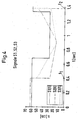
- the signals of the distance sensors S1, S2, S3 can be suitably evaluated will. 4 shows a possible time course of the signals of the distance sensors S1, S2, S3 when the material to be conveyed 2 runs at an angle.
- the material to be conveyed 2 enters the measuring range of the distance sensors S2 and S3.
- the distances to the front edge of the material to be conveyed 2 are measured.
- the measurement signals of the distance sensors S2 and S3 reach their respective minimum, ie at these times the edges pass the distance sensors S2 and S3.
- the signals from the distance sensors S2 and S3 then rise again until the material to be conveyed 2 leaves the measuring range of the distance sensors S2 and S3.
- the signals from the distance sensors S2 and S3 jump back to their starting position.
Landscapes
- Physics & Mathematics (AREA)
- General Physics & Mathematics (AREA)
- Length Measuring Devices By Optical Means (AREA)
- Length Measuring Devices With Unspecified Measuring Means (AREA)
Applications Claiming Priority (2)
| Application Number | Priority Date | Filing Date | Title |
|---|---|---|---|
| DE1995105509 DE19505509C2 (de) | 1995-02-10 | 1995-02-10 | Verfahren und Einrichtung zum Messen des Volumens eines bewegten Fördergutes |
| DE19505509 | 1995-02-10 |
Publications (2)
| Publication Number | Publication Date |
|---|---|
| EP0726445A2 true EP0726445A2 (fr) | 1996-08-14 |
| EP0726445A3 EP0726445A3 (fr) | 1997-11-12 |
Family
ID=7754322
Family Applications (1)
| Application Number | Title | Priority Date | Filing Date |
|---|---|---|---|
| EP96250013A Withdrawn EP0726445A3 (fr) | 1995-02-10 | 1996-01-19 | Procédé et dispositif pour mesurer le volume d'un objet en mouvement |
Country Status (2)
| Country | Link |
|---|---|
| EP (1) | EP0726445A3 (fr) |
| DE (1) | DE19505509C2 (fr) |
Cited By (6)
| Publication number | Priority date | Publication date | Assignee | Title |
|---|---|---|---|---|
| EP0837300A3 (fr) * | 1996-10-21 | 2001-03-21 | Carl Zeiss | Procédé de mesure de contours d'objets |
| EP1070935A3 (fr) * | 1999-07-08 | 2002-04-10 | Bayer Bitterfeld GmbH | Dispositif pour contrôler la largeur de joints de scellement |
| EP1621849A1 (fr) * | 2002-12-20 | 2006-02-01 | Sick Ag | Procédé et dispositif pour la saisie dýobjets déplacés sur une bande dýalimentation à lýaide dýun capteur optoélectronique |
| CN109422092A (zh) * | 2017-08-23 | 2019-03-05 | 中国南玻集团股份有限公司 | 多功能传动台以及板材尺寸测量系统和方法 |
| CN114777702A (zh) * | 2022-04-22 | 2022-07-22 | 成都市绿色快线环保科技有限公司 | 一种堆叠板材体积识别方法及其装置、系统 |
| CN116727084A (zh) * | 2022-03-08 | 2023-09-12 | 克磊镘有限公司 | 确定供应到物料处理装置的进料物料的层高度的方法 |
Families Citing this family (5)
| Publication number | Priority date | Publication date | Assignee | Title |
|---|---|---|---|---|
| DE19721711C2 (de) * | 1997-05-23 | 2002-10-10 | Wipotec Wiege & Positioniersys | Einrichtung zur Formatbestimmung von Stückgut, insbesondere Postsendungen |
| DE19722066A1 (de) * | 1997-05-27 | 1998-12-03 | Smb Schwede Maschinenbau Gmbh | Umreifungsmaschine zum Umreifen von Objekten mit einer objekthöhenabhängigen Rückspanneinrichtung |
| DE19724156C2 (de) * | 1997-06-07 | 2001-12-13 | Fette Wilhelm Gmbh | Verfahren und Vorrichtung zur Messung der Funktionslänge von Preßstempeln |
| DE10315902A1 (de) * | 2003-04-08 | 2004-11-04 | Anatec Gmbh | Verfahren und Anordnung zu Messung eines Volumenstromes |
| CH715506A1 (de) * | 2018-10-31 | 2020-05-15 | Ferag Ag | Speichervorrichtung zum Einspeichern von Transporteinheiten. |
Citations (1)
| Publication number | Priority date | Publication date | Assignee | Title |
|---|---|---|---|---|
| DE2722368A1 (de) | 1976-05-19 | 1977-12-01 | Ultra Sort Corp | Sortiervorrichtung mit optischem abtaster |
Family Cites Families (5)
| Publication number | Priority date | Publication date | Assignee | Title |
|---|---|---|---|---|
| US3588480A (en) * | 1968-12-06 | 1971-06-28 | Fairbanks Morse Inc | Processing control system |
| GB2078937B (en) * | 1980-06-19 | 1984-05-31 | Gen Mining Union Corp | Volumetric measurement of particles |
| US5220536A (en) * | 1989-09-01 | 1993-06-15 | Quantronix, Inc. | Measuring method and apparatus |
| DE4318341B4 (de) * | 1993-04-10 | 2009-02-19 | Christoph Schausten | Verfahren zur Lagerung von Apotheken-Artikeln und Vorrichtung zur Durchführung eines solchen Verfahrens |
| EP0620528B2 (fr) * | 1993-04-10 | 2001-10-31 | Christoph Schausten | Procédé pour le stockage de colis et dispositif pour la mise en oeuvre de ce procédé |
-
1995
- 1995-02-10 DE DE1995105509 patent/DE19505509C2/de not_active Expired - Fee Related
-
1996
- 1996-01-19 EP EP96250013A patent/EP0726445A3/fr not_active Withdrawn
Patent Citations (1)
| Publication number | Priority date | Publication date | Assignee | Title |
|---|---|---|---|---|
| DE2722368A1 (de) | 1976-05-19 | 1977-12-01 | Ultra Sort Corp | Sortiervorrichtung mit optischem abtaster |
Cited By (10)
| Publication number | Priority date | Publication date | Assignee | Title |
|---|---|---|---|---|
| EP0837300A3 (fr) * | 1996-10-21 | 2001-03-21 | Carl Zeiss | Procédé de mesure de contours d'objets |
| EP1070935A3 (fr) * | 1999-07-08 | 2002-04-10 | Bayer Bitterfeld GmbH | Dispositif pour contrôler la largeur de joints de scellement |
| US6717087B1 (en) * | 1999-07-08 | 2004-04-06 | Bayer Bitterfeld Gmbh | Monitoring device for the sealing web width |
| EP1621849A1 (fr) * | 2002-12-20 | 2006-02-01 | Sick Ag | Procédé et dispositif pour la saisie dýobjets déplacés sur une bande dýalimentation à lýaide dýun capteur optoélectronique |
| EP1431707B1 (fr) * | 2002-12-20 | 2006-08-02 | Sick AG | Procédé et dispositif pour l'acquisition, au moyen d'un capteur optoélectronique, d'objets placés sur un convoyeur |
| US7199385B2 (en) | 2002-12-20 | 2007-04-03 | Sick Ag | Method and an apparatus for the detection of objects moved on a conveyor means by means of an optoelectronic sensor |
| CN109422092A (zh) * | 2017-08-23 | 2019-03-05 | 中国南玻集团股份有限公司 | 多功能传动台以及板材尺寸测量系统和方法 |
| CN116727084A (zh) * | 2022-03-08 | 2023-09-12 | 克磊镘有限公司 | 确定供应到物料处理装置的进料物料的层高度的方法 |
| CN114777702A (zh) * | 2022-04-22 | 2022-07-22 | 成都市绿色快线环保科技有限公司 | 一种堆叠板材体积识别方法及其装置、系统 |
| CN114777702B (zh) * | 2022-04-22 | 2024-03-12 | 成都市绿色快线环保科技有限公司 | 一种堆叠板材体积识别方法及其装置、系统 |
Also Published As
| Publication number | Publication date |
|---|---|
| EP0726445A3 (fr) | 1997-11-12 |
| DE19505509C2 (de) | 2003-01-30 |
| DE19505509A1 (de) | 1996-08-14 |
Similar Documents
| Publication | Publication Date | Title |
|---|---|---|
| DE3411540C2 (fr) | ||
| DE3642377A1 (de) | Verfahren und vorrichtung zur abmessung der dicke einer folien- oder blattartigen materialbahn | |
| EP2246673A1 (fr) | Procédé de détermination du volume de produits à transporter et dispositif | |
| DE2546714C2 (fr) | ||
| WO1983000920A1 (fr) | Procede et dispositif pour evaluer les coups sur une cible | |
| DE3735905A1 (de) | Verfahren und vorrichtung zur volumenstrommessung auf bandfoerderern mittels laser-entfernungsprofilscanner | |
| EP1024372B1 (fr) | Dispositif pour détecter la position | |
| DE19505509C2 (de) | Verfahren und Einrichtung zum Messen des Volumens eines bewegten Fördergutes | |
| DE2713844C3 (de) | Vorrichtung zum Erkennen der Wertigkeit von Münzen o.dgl. Gegenstände | |
| DE3784383T2 (de) | Verfahren zum messen von filmdicken und vorrichtung dafuer. | |
| DE2555975B2 (de) | Einrichtung zum Feststellen bzw. Oberwachen der Abmessung eines ggf. bewegten Gegenstandes | |
| EP0361071B1 (fr) | Procédé et dispositif de comptage d'objets plats arrivant en chevauchement tels que des feuilles, des revues et similaires | |
| EP1653202A1 (fr) | Procédé et dispositif pour mesurer un flux volumique sur un transporteur a courroie | |
| DE3913159A1 (de) | Verfahren und vorrichtung zur messung von wellenfoermigen deformationen an wenigstens einer schienenoberseite (schienenlaufflaeche) eines schienenweges | |
| DE2232207C3 (de) | Verfahren und Vorrichtung zur Abstandsmessung, insbesondere zur Feinmessung an Werkstücken | |
| DE2124444C3 (de) | Verfahren zum Bestimmen der Dicke oder Breite von ebenen Werkstucken | |
| DE69629482T2 (de) | Verfahren und Apparat zur Volumenmessung eines Gegenstandes mittels eines Laserabtasters | |
| DE2436510A1 (de) | Vorrichtung zur bestimmung der position eines stueckes | |
| DE3522809C2 (fr) | ||
| DE19625055B4 (de) | Vorrichtung und Verfahren zur Durchmessererfassung von Gegenständen | |
| DE19539706C2 (de) | Vorrichtung zum Überprüfen eines Klebstoffauftragzustands | |
| AT509885B1 (de) | Vorrichtung und verfahren zur münzerkennung | |
| DE3783137T2 (de) | Regelvorrichtung fuer foerderanlagen. | |
| WO2005022079A1 (fr) | Dispositif pour determiner le volume de biens a transporter | |
| EP4040188B1 (fr) | Dispositif et procédé de mesure d'un objet |
Legal Events
| Date | Code | Title | Description |
|---|---|---|---|
| PUAI | Public reference made under article 153(3) epc to a published international application that has entered the european phase |
Free format text: ORIGINAL CODE: 0009012 |
|
| AK | Designated contracting states |
Kind code of ref document: A2 Designated state(s): AT DE DK FR GB IT NL |
|
| PUAL | Search report despatched |
Free format text: ORIGINAL CODE: 0009013 |
|
| AK | Designated contracting states |
Kind code of ref document: A3 Designated state(s): AT DE DK FR GB IT NL |
|
| 17P | Request for examination filed |
Effective date: 19980512 |
|
| 17Q | First examination report despatched |
Effective date: 20010424 |
|
| STAA | Information on the status of an ep patent application or granted ep patent |
Free format text: STATUS: THE APPLICATION HAS BEEN WITHDRAWN |
|
| 18W | Application withdrawn |
Withdrawal date: 20010830 |