EP0726511A2 - Vanne de régulation de pression - Google Patents
Vanne de régulation de pression Download PDFInfo
- Publication number
- EP0726511A2 EP0726511A2 EP95119118A EP95119118A EP0726511A2 EP 0726511 A2 EP0726511 A2 EP 0726511A2 EP 95119118 A EP95119118 A EP 95119118A EP 95119118 A EP95119118 A EP 95119118A EP 0726511 A2 EP0726511 A2 EP 0726511A2
- Authority
- EP
- European Patent Office
- Prior art keywords
- pressure
- connection
- actuator
- control
- valve according
- Prior art date
- Legal status (The legal status is an assumption and is not a legal conclusion. Google has not performed a legal analysis and makes no representation as to the accuracy of the status listed.)
- Granted
Links
Images
Classifications
-
- G—PHYSICS
- G05—CONTROLLING; REGULATING
- G05D—SYSTEMS FOR CONTROLLING OR REGULATING NON-ELECTRIC VARIABLES
- G05D16/00—Control of fluid pressure
- G05D16/04—Control of fluid pressure without auxiliary power
- G05D16/06—Control of fluid pressure without auxiliary power the sensing element being a flexible membrane, yielding to pressure, e.g. diaphragm, bellows, capsule
- G05D16/063—Control of fluid pressure without auxiliary power the sensing element being a flexible membrane, yielding to pressure, e.g. diaphragm, bellows, capsule the sensing element being a membrane
- G05D16/0644—Control of fluid pressure without auxiliary power the sensing element being a flexible membrane, yielding to pressure, e.g. diaphragm, bellows, capsule the sensing element being a membrane the membrane acting directly on the obturator
- G05D16/0663—Control of fluid pressure without auxiliary power the sensing element being a flexible membrane, yielding to pressure, e.g. diaphragm, bellows, capsule the sensing element being a membrane the membrane acting directly on the obturator using a spring-loaded membrane with a spring-loaded slideable obturator
-
- G—PHYSICS
- G05—CONTROLLING; REGULATING
- G05D—SYSTEMS FOR CONTROLLING OR REGULATING NON-ELECTRIC VARIABLES
- G05D16/00—Control of fluid pressure
- G05D16/04—Control of fluid pressure without auxiliary power
- G05D16/10—Control of fluid pressure without auxiliary power the sensing element being a piston or plunger
- G05D16/101—Control of fluid pressure without auxiliary power the sensing element being a piston or plunger the controller being arranged as a multiple-way valve
-
- G—PHYSICS
- G05—CONTROLLING; REGULATING
- G05D—SYSTEMS FOR CONTROLLING OR REGULATING NON-ELECTRIC VARIABLES
- G05D16/00—Control of fluid pressure
- G05D16/14—Control of fluid pressure with auxiliary non-electric power
- G05D16/18—Control of fluid pressure with auxiliary non-electric power derived from an external source
- G05D16/185—Control of fluid pressure with auxiliary non-electric power derived from an external source using membranes within the main valve
-
- Y—GENERAL TAGGING OF NEW TECHNOLOGICAL DEVELOPMENTS; GENERAL TAGGING OF CROSS-SECTIONAL TECHNOLOGIES SPANNING OVER SEVERAL SECTIONS OF THE IPC; TECHNICAL SUBJECTS COVERED BY FORMER USPC CROSS-REFERENCE ART COLLECTIONS [XRACs] AND DIGESTS
- Y10—TECHNICAL SUBJECTS COVERED BY FORMER USPC
- Y10T—TECHNICAL SUBJECTS COVERED BY FORMER US CLASSIFICATION
- Y10T137/00—Fluid handling
- Y10T137/2278—Pressure modulating relays or followers
- Y10T137/2409—With counter-balancing pressure feedback to the modulating device
-
- Y—GENERAL TAGGING OF NEW TECHNOLOGICAL DEVELOPMENTS; GENERAL TAGGING OF CROSS-SECTIONAL TECHNOLOGIES SPANNING OVER SEVERAL SECTIONS OF THE IPC; TECHNICAL SUBJECTS COVERED BY FORMER USPC CROSS-REFERENCE ART COLLECTIONS [XRACs] AND DIGESTS
- Y10—TECHNICAL SUBJECTS COVERED BY FORMER USPC
- Y10T—TECHNICAL SUBJECTS COVERED BY FORMER US CLASSIFICATION
- Y10T137/00—Fluid handling
- Y10T137/8593—Systems
- Y10T137/86919—Sequentially closing and opening alternately seating flow controllers
-
- Y—GENERAL TAGGING OF NEW TECHNOLOGICAL DEVELOPMENTS; GENERAL TAGGING OF CROSS-SECTIONAL TECHNOLOGIES SPANNING OVER SEVERAL SECTIONS OF THE IPC; TECHNICAL SUBJECTS COVERED BY FORMER USPC CROSS-REFERENCE ART COLLECTIONS [XRACs] AND DIGESTS
- Y10—TECHNICAL SUBJECTS COVERED BY FORMER USPC
- Y10T—TECHNICAL SUBJECTS COVERED BY FORMER US CLASSIFICATION
- Y10T137/00—Fluid handling
- Y10T137/8593—Systems
- Y10T137/87169—Supply and exhaust
- Y10T137/87217—Motor
- Y10T137/87225—Fluid motor
Definitions
- the invention relates to a pressure control valve, with a primary pressure connection for supplying pressure medium, a pressure-controlled secondary pressure connection for connection to a consumer, and a ventilation connection, further with an actuating device which can be positioned in various control positions by means of a variable control pressure prevailing in a control chamber which is in a neutral position, at least one feed position and at least one vent position, the secondary pressure connection in the neutral position being separated from both the primary pressure connection and the ventilation connection, while in the possible supply and ventilation positions in each case either with the primary pressure connection or connected to the vent connection and at the same time separated from the other connection.
- a pressure regulating valve of this type is based on the Japanese unexamined patent application with the publication no. JP-H5-158 552. It regulates the comparison by changing the control position of the control device to the primary pressure lower secondary pressure to a pressure value desired at the connected consumer.
- the actuating device In order to increase the secondary pressure, the actuating device is held in a feed position; a reduction in the secondary pressure is brought about by positioning the actuating device in a venting position.
- a variable control pressure which acts on the actuator and is made available in a control chamber, is used to specify a respective control position.
- a certain inadequacy in operation arises from the fact that complete venting of the secondary pressure connection is generally not possible in the known pressure control valve. Even if the control chamber is completely vented with the effect that the ambient pressure, ie atmospheric pressure, prevails in the control chamber, the actuating device assumes the neutral position before the secondary pressure connection is completely depressurized. Complete venting of the secondary pressure connection can thus only be achieved by additional measures, for example by switching on a separate vent valve in the connection between the secondary pressure connection and the assigned consumer.
- the actuating device is acted upon by a mechanical spring device which counteracts the direction of action of the control pressure in such a way that it automatically assumes a basic position which corresponds to a venting position when the ambient pressure prevails in the control chamber.
- the secondary pressure connection is also automatically depressurized without having to operate any external valve devices.
- the actuating device is exposed to other influences which affect the required actuating force. These can be frictional forces or unbalanced spring forces of other spring arrangements due to tolerances.
- a suitable design of the additional mechanical spring device counteracting the control pressure ensures that, despite the influences mentioned, there is at least a slight venting position if the control pressure corresponds to the ambient pressure, that is to say no excess pressure is present.
- the spring device counteracting the control pressure is expediently designed in such a way that the overflow cross section between the secondary pressure connection and the venting connection available in the basic position is smaller than the maximum adjustable overflow cross section during operation of the pressure control valve. This ensures that the pressure difference (offset) between the control pressure and the secondary pressure is as small as possible, so that the pressure values of the control pressure to be made available for the operation of the pressure control valve can be kept low.
- the actuating device expediently comprises a preferably rod-shaped actuator which can act during the control movements on two closure members movable relative to it, one of which has an overflow opening between the secondary pressure connection and the primary pressure connection and the other an overflow opening between the secondary pressure connection and the Vent port is assigned.
- the closure members are biased by spring arrangements independent of the mechanical spring device into a closed position closing the associated overflow opening, which they in the Take neutral position of the control device.
- Actuating parts provided on the actuator act on one or the other locking element when adjusting the actuator depending on the direction of deflection in the opening direction, while the other remains unchanged in the closed position.
- closure members are expediently arranged axially displaceably on the actuator from which they can be passed.
- the actuator is preferably suspended movably on the valve housing via a flexible, expediently elastic membrane.
- This membrane forms a wall section of the control chamber, so that it enables the required control movement when the control pressure is applied.
- a back pressure chamber which constantly communicates with the secondary pressure connection, the spring device responsible for the basic position being expediently accommodated in the back pressure chamber.
- closure members are expediently balanced pressure.
- the end faces of the two closure members opposite the assigned valve seat can be of the same magnitude and constantly acted upon by the secondary pressure.
- the pneumatic pressure control valve according to the example is a quantity booster which could also be referred to as a "pneumatic booster". With a pressure gain of 1: 1, for example, it can significantly increase the flow rate of a small pilot valve. It mainly serves proportional applications.
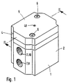
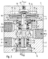
- the pressure control valve shown has a multi-part valve housing 1, consisting of a base body 2, an intermediate plate 4 attached to an axial end face 3 of the base body 2 and one on the intermediate plate 4 seated end plate 5. The latter is screwed to the base body 2 by means of screws 6, the intermediate plate 4 in between also being held.
- a primary pressure connection (P) 8 On the lateral outer surface of the base body 2 there are a plurality of openings 7 which are assigned to a primary pressure connection (P) 8, a secondary pressure connection (A) 9 and a ventilation connection (R) 10.
- connection 8, 9, 10 open out in the interior of the base body 2 into an axially extending receiving space 13 for parts of an actuating device accommodated in the valve housing 1 and generally designated by 14.
- the receiving space 13 is contoured essentially cylindrically, but stepped several times in the longitudinal direction.
- the receiving space 13 opens into a working space 17 formed in the intermediate plate 4 and / or the end plate 5.
- the opposite end face 15 of the base body 2 which faces downward in FIG him sealing cap 16 sealed.
- the actuating device 14 comprises a rod-shaped actuator 18, which extends coaxially in the receiving space 13 and protrudes into the working space 17 with an end section 22.
- a loading device 23 is arranged on the end section 22, which axially and sealingly divides the working space 17 into a control chamber 24 assigned to the end plate 5 and a counter-pressure chamber 25 assigned to the base body 2.
- the loading device 23 can be moved together with the actuator 18 in the longitudinal direction of the working space 17. The corresponding movement is called a control movement.
- the receiving space 13 is in direct connection with the back pressure chamber 25.
- the secondary pressure connection 9 is connected to the primary pressure connection 8 via a first overflow opening 26 defined in the receiving space 13. Furthermore, it is connected to the vent connection 10 via a second overflow opening 27 which is arranged at an axial distance from the first overflow opening 26 and is also located in the receiving space 13.
- the overflow cross-sections provided by the overflow openings 26, 27 can be variably and continuously adjusted via the control movement of the actuator 18.
- the secondary pressure connection 9 opens into the receiving space 13 in the intermediate section 28 arranged axially between the two overflow openings 26, 27.
- the primary pressure connection 8 opens into the first end section 32 of the receiving space 13, which axially adjoins the first overflow opening 26 in the direction of the closure cover 16.
- the vent connection 10 opens into the second end section 33 of the receiving space 13, which is located on the axial side of the intermediate section opposite the first end section 32 28 is located.
- the first end section 32 is delimited by the closure cover 16.
- the second end section 33 is partitioned off from the adjoining back pressure chamber 25 by a partition wall 34.
- Each overflow opening 26, 27 is surrounded by an annular valve seat 35, 36 which is fixed to the housing and points axially away from the intermediate section 28.
- a first closure member 37 In the first end section 32 there is a first closure member 37, in the second end section 33 a second closure member 38 is arranged. Both locking members 37, 38 are axially movable in the associated end section 32, 33, so the possible direction of movement coincides with the direction of the control movement of the actuator 18.
- Each closure member 37, 38 can assume a closed position, in which it lies tightly against the associated valve seat 35, 36 and thereby completely closes the associated overflow opening 26, 27. In this case, the connection of the secondary pressure connection 9 to the assigned Primary pressure port 8 or vent port 10 interrupted. Furthermore, each closure member 37, 38 can assume various open positions, in which it is raised by a more or less large amount from the associated valve seat 35, 36, so that it can provide different overflow cross-sections for the pressure medium in accordance with the degree of opening.
- Each closure member 37, 38 is acted upon by a spring arrangement 42 in the closing direction.
- this is formed by a helical compression spring. It is supported on the one hand on the respective closure member 37, 38 and on the other hand on the associated closure cover 16 or on the partition 34. If there is no counterforce, the closure members 37, 38 are held in the closed positions by the spring forces of the spring arrangements 42.
- the first closure member 37 is axially movably guided in a recess 43 of the closure cover 16. In the area of leadership contact z. B. by a arranged on the movable closure member 37 sealing ring 44 a seal that prevents that at the primary pressure port 8 pressure medium coming into the recess 43.
- the second closure member 38 is in an opening 45 passing through the partition 34 guided axially displaceable.
- a sealing ring 44 ′ prevents a pressure medium flow between the counter pressure chamber 25 and the second end section 33 of the receiving space 13.
- the two closure members 37, 38 are coaxially penetrated by the actuator 18 as shown.
- a respective closure member 37, 38 and the actuator 18 are axially movable relative to each other.
- each closure member 37, 38 is assigned a movement stop, which is referred to as the actuating part 46, 46 'and is fixedly and in particular integrally connected to the actuator 18.
- the arrangement is such that the actuating parts 46, 46 'can only act against the closing force of the spring arrangements 42 on the associated closure member 37, 38.
- they are located in the longitudinal section of the actuator 18 which extends axially between the two closure members 37, 38.
- This position of the actuator 18 or the entire Actuating device 14 is referred to as the neutral position.
- the secondary pressure connection 9 is tightly separated both from the primary pressure connection 8 and from the ventilation connection 10.
- pneumatic pressure medium is present at the primary pressure connection 8 under a primary pressure.
- the relevant opening 7 is connected to a suitable pressure medium source.
- the secondary pressure connection 9, which is the working connection, is connected to a consumer who is to be supplied with a certain amount of the pressure medium, which is under a constant secondary pressure as possible. This secondary pressure can correspond to the primary pressure, but will regularly be lower.
- the level of the secondary pressure is set by the adjusting device 14.
- the adjusting device 14 remains in the neutral position explained. If the secondary pressure falls below the desired setpoint, the actuator 18 moves in the direction of the lower end face 15, its first actuating part 46 lifting the first closure member 37 off the associated valve seat. As a result, pressure medium flows from the primary pressure connection 8 to the secondary pressure connection 9, which is one there Pressure increase causes.
- the relevant control position of the actuating device 14 is referred to as the feed position. Different feed positions are possible, which differ in the amount of the overflow cross section made available in each case.
- the second overflow opening 27 remains closed in all feed positions. As a result of the relative movement between the moving actuator 18 and the stationary second closure element 38, the actuating part 46 'has moved away from the end face 47 of the assigned second closure element 38 by a more or less large amount.
- the actuator 18 shifts in the opposite direction, that is to say upwards in FIG. 2.
- the actuating part 46 has reached the second closure member 38, the latter is lifted off the first valve seat 36, the first overflow opening 26 already being closed again at the time of the lift-off.
- pressure medium can flow out of the secondary pressure connection 9 via the vent connection 10.
- the control position in question is referred to as the vent position.
- different venting positions are also possible here.
- the described control movement of the adjusting device 14 is influenced by a control pressure P CONTROL , with which the control chamber 24 is acted upon. According to the example, it is supplied via a control channel 48 which opens out on the end face of the end plate 5.
- the control pressure acts on the actuating device 23 connected to the actuator 18, so that the actuator 18 is actuated in the direction of the feed position.
- the control pressure is counteracted by the currently prevailing secondary pressure which is present in the back pressure chamber 25.
- the back pressure chamber 25 is connected to the secondary pressure connection 9 via a connecting channel 52 formed in the valve housing 1.
- the secondary pressure acts on the actuator 18 in the direction of the venting position via the application device 23.
- the counterforce counteracting the control pressure force is, however, also supported by a mechanical spring device 53 which constantly acts on the actuator 18 in the direction of the ventilation positions.
- this spring device 53 is located in the counter-pressure chamber as shown. In the present case, it is formed by a helical compression spring, which protrudes on the one hand on the wall part of the counter-pressure chamber 25 formed by the partition wall 34 and on the other hand protrudes from the actuator 18 in the manner of a radial projection Acting device 23 supports.
- variable control pressure P CONTROL is expediently provided by a pilot valve device , not shown. Its value depends on the actual value of the secondary pressure, which can be detected by a pressure sensor, not shown, depending on the level of which the pilot valve device is actuated.
- the control pressure can be provided, for example, via two switching valves actuated by pulse duration modulation or in some other way.
- the spring device 53 ensures that the actuating device 14 assumes a basic position when the control chamber 24 is depressurized, as is indicated by way of example in FIG. 2.
- This basic position is a ventilation position, as already mentioned above. Said basic position is adopted automatically or automatically when the control pressure is zero, that is to say corresponds to the prevailing ambient pressure.
- the coordination is made such that the overflow cross section a provided in the basic position between the secondary pressure connection 9 and the vent connection 10 is less than the maximum overflow cross section possible with maximum deflection of the assigned second closure member 38.
- the minimum ventilation position is sufficient to achieve the desired effect. This advantageously enables the use of a relatively weak spring device 53, so that an excessively increased control pressure P CONTROL is not required to operate the pressure regulating valve .
- the actuating device 14 is expediently fixed in the basic position on the basis of a mechanical balance of forces between the spring device 53 mentioned and the spring arrangement 42 acting on the closure member 38 assigned to the venting connection 10.
- the application device 23 comprises two axially staggered application disks 54, 54 ', which are arranged coaxially to the actuator 18 and fixed thereon, for example, by a screw connection are. Its outer diameter is smaller than the inner diameter of the working space 17. Furthermore, the loading device 23 comprises an air-impermeable membrane 55 made of flexible, elastic material, via which the actuator 18 is suspended on the valve housing 1 in an axially movable manner. It preferably consists of material with rubber-elastic properties. It effects a fluid-tight separation between the control chamber 24 and the back pressure chamber 25.
- the membrane 55 shown in FIG. 2 is fixed with its outer edge 56 fixed to the housing all around. It is preferably firmly clamped between the intermediate plate 4 and the end plate 5.
- the membrane 55 also has a central opening 57 with which it is attached to the end section 22 of the actuator 18. It is held in place there by the two loading discs 54, 54 ', which clamp the edge 58 surrounding the opening 57 between them.
- At least the radially outer areas of the diaphragm 55 form a movable wall section of the control chamber 24 and the counter-pressure chamber 25. It is removed in the same way as the loading disks 54, 54 'from the pressure prevailing in the two chambers 24, 25.
- the annular gap 59 which receives it between the two loading disks 54, 54 'widens radially outwards.
- a pressure force equalization channel 64 is provided which constantly connects the recess 43 to the secondary pressure connection 9.
- this channel is formed by a longitudinal groove, which is recessed on the outer circumference of that section of the actuator 18 on which the first closure member 37 is longitudinally movable.
- the pressure force compensation channel 64 could also run in the valve housing or inside the actuator 18. Also the connecting channel 52 could be formed in the interior of the actuator 18.
- a channel guide would be conceivable, as indicated by dash-dotted lines in FIG. 2, a channel 65 running longitudinally in the actuator 18 opening at one end to the recess 43 and at the other end to the counter-pressure chamber 25, and a branch channel 66 extending from this channel 65 to the intermediate section 28 being open .
- the pressure control valve has a good control quality, since the two closure members 37, 38 are mechanically decoupled from one another, so that the function of the other remains unaffected in the event of the oscillation of one closure member. Since there is pressure compensation, it is sufficient to make the spring assemblies 42 overall only so strong that they overcome the possibly occurring weight forces and the frictional forces.
- the friction occurring in the exemplary embodiment between the sealing rings 44, 44 'and the associated contact surface fixed to the housing has a functional effect only in one direction, so that the hysteresis of the valve is not influenced.
- the valve works very stable overall, which is particularly important in control loops, where you can use this concept to achieve higher levels of accuracy and significantly less Tendency to vibrate.
- the pressure force compensation is also realized in that the two valve seats 35, 36 are of the same size. Due to the suspension on a membrane 55, a frictionless power transmission is possible. The spring support of the spring device 53 makes it possible for the secondary pressure connection 9 to be in a depressurized state.
Landscapes
- Physics & Mathematics (AREA)
- Engineering & Computer Science (AREA)
- Fluid Mechanics (AREA)
- General Physics & Mathematics (AREA)
- Automation & Control Theory (AREA)
- Power Engineering (AREA)
- Control Of Fluid Pressure (AREA)
Applications Claiming Priority (2)
| Application Number | Priority Date | Filing Date | Title |
|---|---|---|---|
| DE19504364A DE19504364C2 (de) | 1995-02-10 | 1995-02-10 | Druckregelventil |
| DE19504364 | 1995-02-10 |
Publications (3)
| Publication Number | Publication Date |
|---|---|
| EP0726511A2 true EP0726511A2 (fr) | 1996-08-14 |
| EP0726511A3 EP0726511A3 (fr) | 1998-04-22 |
| EP0726511B1 EP0726511B1 (fr) | 2001-08-01 |
Family
ID=7753599
Family Applications (1)
| Application Number | Title | Priority Date | Filing Date |
|---|---|---|---|
| EP95119118A Expired - Lifetime EP0726511B1 (fr) | 1995-02-10 | 1995-12-05 | Vanne de régulation de pression |
Country Status (3)
| Country | Link |
|---|---|
| US (1) | US5682918A (fr) |
| EP (1) | EP0726511B1 (fr) |
| DE (2) | DE19504364C2 (fr) |
Cited By (6)
| Publication number | Priority date | Publication date | Assignee | Title |
|---|---|---|---|---|
| EP2236840A3 (fr) * | 2009-03-30 | 2011-06-22 | STI Srl | Vanne amplificatrice |
| CN103939639A (zh) * | 2009-11-10 | 2014-07-23 | 滨特尔阀门控制美国有限合伙公司 | 改进的压力恢复节能器阀 |
| US9062798B2 (en) | 2011-11-12 | 2015-06-23 | Festo Ag & Co. Kg | Pressure regulating device and method of operating a pressure regulating device |
| EP3284988A1 (fr) * | 2010-09-15 | 2018-02-21 | Fisher Controls International Llc | Servomoteur comportant un surpresseur de volume |
| US10437267B2 (en) | 2014-11-17 | 2019-10-08 | Krones Ag | Pressure regulator device and method of using same |
| WO2022136379A1 (fr) * | 2020-12-22 | 2022-06-30 | Danfoss A/S | Soupape à voies multiples dotée d'une soupape de régulation de pression |
Families Citing this family (27)
| Publication number | Priority date | Publication date | Assignee | Title |
|---|---|---|---|---|
| DE19731417A1 (de) * | 1997-07-22 | 1999-01-28 | Itt Mfg Enterprises Inc | Ventileinrichtung |
| GB9804047D0 (en) * | 1998-02-27 | 1998-04-22 | Normalair Garrett Ltd | Method of controlling a parameter |
| JP4081861B2 (ja) * | 1998-07-02 | 2008-04-30 | Smc株式会社 | 流体圧機器用手動給排切換弁 |
| NZ334938A (en) * | 1999-03-31 | 2000-07-28 | Peter Michael Bradley | Pressure reducing valve for LP hot water cylinder, pressure sensitive member varies in size with changes in pressure |
| JP3280003B2 (ja) * | 1999-10-18 | 2002-04-30 | エスエムシー株式会社 | 電磁弁集合体用給排気装置 |
| DE20119470U1 (de) | 2001-11-29 | 2002-01-31 | FESTO AG & Co., 73734 Esslingen | Differenzdruck-Proportionalventil |
| DE10213092B4 (de) * | 2002-03-23 | 2004-05-13 | Heinz Knocks | Druckregelventil |
| JP4695453B2 (ja) * | 2005-07-29 | 2011-06-08 | 株式会社豊田中央研究所 | 方向制御弁 |
| EP1758007B1 (fr) * | 2005-08-23 | 2007-12-12 | Festo Ag & Co. | Régulateur de position actionné par fluide |
| EP1832950A1 (fr) | 2006-03-11 | 2007-09-12 | FESTO AG & Co | Régulateur pour commander une pression utilisateur |
| US9341281B2 (en) | 2007-02-12 | 2016-05-17 | Colt Irrigation Llc | Fluid activated flow control apparatus |
| US8397745B2 (en) | 2007-02-12 | 2013-03-19 | Colt Irrigation, LLC | Fluid activated flow control apparatus |
| US20090032746A1 (en) * | 2007-07-31 | 2009-02-05 | Caterpillar Inc. | Piezo-electric actuated valve |
| US20090283160A1 (en) * | 2008-05-02 | 2009-11-19 | James Fishwick | Fluid flow control device and control circuit |
| US20100264348A1 (en) * | 2009-04-20 | 2010-10-21 | Food Global Technologies LLC | Dynamic Bore Plug Assembly |
| US10571937B1 (en) | 2014-01-23 | 2020-02-25 | Colt Irrigation, LLC | Valve control apparatus |
| US10088849B2 (en) | 2014-01-23 | 2018-10-02 | Colt Irrigation, LLC | Fluid activated flow control apparatus |
| US9599286B2 (en) | 2014-01-23 | 2017-03-21 | Colt Irrigation, LLC | Fluid activated flow control apparatus |
| NL2013449B1 (en) * | 2014-09-10 | 2016-09-28 | Asco Controls Bv | A control valve having a piston-cylinder control system which connects centrally in between supply and exhaust valves to an operating member. |
| DE102016102388A1 (de) * | 2016-02-11 | 2017-08-17 | Hoerbiger Automatisierungstechnik Holding Gmbh | Proportionalventil |
| CN105757029A (zh) * | 2016-05-03 | 2016-07-13 | 胡和萍 | 一种液压式气缸控压调节器 |
| DE102016112356A1 (de) * | 2016-07-06 | 2018-01-11 | Smc Pneumatik Gmbh | Ventilvorrichtung mit einer Ablassfunktion für einen Restdruck, Pneumatikzylindereinrichtung mit einer solchen sowie Verfahren zur Entlüftung einer solchen Pneumatikzylindereinrichtung |
| EP3688317B1 (fr) * | 2017-09-29 | 2023-05-10 | Fisher Controls International Llc | Vanne relais et méthode d'équilibrage de la force |
| MX2021002903A (es) * | 2018-09-25 | 2021-06-08 | Hendrickson Usa Llc | Regulador accionado por valvula auxiliar con presion de suministro minimo ajustable. |
| JP7009525B2 (ja) * | 2020-01-31 | 2022-01-25 | 株式会社日本ピスコ | 調圧弁 |
| US12253100B2 (en) * | 2021-11-30 | 2025-03-18 | Dresser, Llc | Eliminating bleed on flow controls |
| CN120868209B (zh) * | 2025-09-24 | 2025-11-28 | 江苏合球机械科技有限公司 | 一种便于调节水流量的节能型水泵控制阀 |
Family Cites Families (8)
| Publication number | Priority date | Publication date | Assignee | Title |
|---|---|---|---|---|
| US2012596A (en) * | 1933-04-19 | 1935-08-27 | Koppel Ind Car & Equipment Co | Fluid pressure valve |
| US2985490A (en) * | 1959-10-05 | 1961-05-23 | Bendix Westinghouse Automotive | Fluid pressure valve |
| GB1063241A (en) * | 1962-09-14 | 1967-03-30 | Drallim Ltd | Pressure control valves |
| US3354894A (en) * | 1965-12-07 | 1967-11-28 | Kurt Stoll Kg Maschinen U Appb | Valve mechanism |
| DE2138658A1 (de) * | 1971-08-03 | 1973-02-15 | Festo Maschf Stoll G | Ventilanordnung |
| US4327773A (en) * | 1979-12-26 | 1982-05-04 | Schmelzer Corporation | Valve assembly |
| DE3722315A1 (de) * | 1987-07-07 | 1989-01-19 | Joucomatic Gmbh | Druckregelventil |
| JP2589424B2 (ja) * | 1991-12-06 | 1997-03-12 | シーケーディ株式会社 | 圧力制御弁 |
-
1995
- 1995-02-10 DE DE19504364A patent/DE19504364C2/de not_active Expired - Fee Related
- 1995-12-05 EP EP95119118A patent/EP0726511B1/fr not_active Expired - Lifetime
- 1995-12-05 DE DE59509465T patent/DE59509465D1/de not_active Expired - Lifetime
-
1996
- 1996-02-08 US US08/598,359 patent/US5682918A/en not_active Expired - Lifetime
Cited By (7)
| Publication number | Priority date | Publication date | Assignee | Title |
|---|---|---|---|---|
| EP2236840A3 (fr) * | 2009-03-30 | 2011-06-22 | STI Srl | Vanne amplificatrice |
| US8522818B2 (en) | 2009-03-30 | 2013-09-03 | Sti Srl | Booster valve |
| CN103939639A (zh) * | 2009-11-10 | 2014-07-23 | 滨特尔阀门控制美国有限合伙公司 | 改进的压力恢复节能器阀 |
| EP3284988A1 (fr) * | 2010-09-15 | 2018-02-21 | Fisher Controls International Llc | Servomoteur comportant un surpresseur de volume |
| US9062798B2 (en) | 2011-11-12 | 2015-06-23 | Festo Ag & Co. Kg | Pressure regulating device and method of operating a pressure regulating device |
| US10437267B2 (en) | 2014-11-17 | 2019-10-08 | Krones Ag | Pressure regulator device and method of using same |
| WO2022136379A1 (fr) * | 2020-12-22 | 2022-06-30 | Danfoss A/S | Soupape à voies multiples dotée d'une soupape de régulation de pression |
Also Published As
| Publication number | Publication date |
|---|---|
| EP0726511A3 (fr) | 1998-04-22 |
| DE59509465D1 (de) | 2001-09-06 |
| US5682918A (en) | 1997-11-04 |
| EP0726511B1 (fr) | 2001-08-01 |
| DE19504364C2 (de) | 1998-08-27 |
| DE19504364A1 (de) | 1996-08-14 |
Similar Documents
| Publication | Publication Date | Title |
|---|---|---|
| EP0726511B1 (fr) | Vanne de régulation de pression | |
| EP1118921B1 (fr) | Vanne de régulation de pression ayant des moyens secondaires de mise à l'atmosphère | |
| DE10084851B3 (de) | Regulierventil für konstanten Durchfluß | |
| EP0321774B1 (fr) | Vanne à tiroir avec régulation de quantité | |
| DE1965144C3 (de) | Steuerventil für ein Druckausgleichsventil | |
| DE3305092C2 (fr) | ||
| DE2113011A1 (de) | Druckluftregler fuer eine Anzahl von Druckwerten | |
| DE69015488T2 (de) | Pneumatisches Relais mit vier Arbeitsweisen. | |
| DE3244920A1 (de) | Einrichtung zum veraendern der auf ein stellglied einwirkenden kraft | |
| DE2436891A1 (de) | Logische fluidumsteuervorrichtung | |
| DE29705703U1 (de) | Servogesteuertes Wasserventil | |
| DE1555433A1 (de) | Regelventil fuer druckmittelbetaetigte Bremssysteme | |
| EP1832950A1 (fr) | Régulateur pour commander une pression utilisateur | |
| EP0147589A2 (fr) | Régulateur de pression commandé par force | |
| DE2905199C3 (de) | Vorrichtung zur Regelung des Unterdruckes in einem Unterdruckleitungssystem, insbesondere für Melkanlagen | |
| EP0764803B1 (fr) | Soupape | |
| EP0838744A1 (fr) | Régulateur de pression équipé d'une fonction d'interruption | |
| DE2118970B2 (de) | Druckregler | |
| EP1146268A2 (fr) | Dispositif de commande d'une soupape | |
| DE2308191C3 (de) | Druckregelventil | |
| DE3306777C2 (de) | Gasregelventil | |
| EP0838381B1 (fr) | Installation pour la correction de la force de freinage commandée en fonction de la charge | |
| EP1711712B1 (fr) | Soupape proportionnelle a pression differentielle | |
| EP0369090A1 (fr) | Vanne régulatrice avec compensation de pression | |
| DE20119470U1 (de) | Differenzdruck-Proportionalventil |
Legal Events
| Date | Code | Title | Description |
|---|---|---|---|
| PUAI | Public reference made under article 153(3) epc to a published international application that has entered the european phase |
Free format text: ORIGINAL CODE: 0009012 |
|
| AK | Designated contracting states |
Kind code of ref document: A2 Designated state(s): CH DE FR GB IT LI |
|
| RAP1 | Party data changed (applicant data changed or rights of an application transferred) |
Owner name: FESTO AG & CO |
|
| PUAL | Search report despatched |
Free format text: ORIGINAL CODE: 0009013 |
|
| AK | Designated contracting states |
Kind code of ref document: A3 Designated state(s): CH DE FR GB IT LI |
|
| 17P | Request for examination filed |
Effective date: 19980512 |
|
| 17Q | First examination report despatched |
Effective date: 19991029 |
|
| GRAG | Despatch of communication of intention to grant |
Free format text: ORIGINAL CODE: EPIDOS AGRA |
|
| GRAG | Despatch of communication of intention to grant |
Free format text: ORIGINAL CODE: EPIDOS AGRA |
|
| GRAH | Despatch of communication of intention to grant a patent |
Free format text: ORIGINAL CODE: EPIDOS IGRA |
|
| GRAH | Despatch of communication of intention to grant a patent |
Free format text: ORIGINAL CODE: EPIDOS IGRA |
|
| GRAA | (expected) grant |
Free format text: ORIGINAL CODE: 0009210 |
|
| AK | Designated contracting states |
Kind code of ref document: B1 Designated state(s): CH DE FR GB IT LI |
|
| REG | Reference to a national code |
Ref country code: CH Ref legal event code: EP |
|
| REG | Reference to a national code |
Ref country code: CH Ref legal event code: NV Representative=s name: TROESCH SCHEIDEGGER WERNER AG |
|
| REF | Corresponds to: |
Ref document number: 59509465 Country of ref document: DE Date of ref document: 20010906 |
|
| ITF | It: translation for a ep patent filed | ||
| GBT | Gb: translation of ep patent filed (gb section 77(6)(a)/1977) |
Effective date: 20011106 |
|
| EN | Fr: translation not filed | ||
| REG | Reference to a national code |
Ref country code: GB Ref legal event code: IF02 |
|
| EN | Fr: translation not filed |
Free format text: BO 01/52 PAGES: 283, IL Y A LIEU DE SUPPRIMER: LA MENTION DE LA NON REMISE. LA REMISE EST PUBLIEE DANS LE PRESENT BOPI. |
|
| ET | Fr: translation filed | ||
| PLBE | No opposition filed within time limit |
Free format text: ORIGINAL CODE: 0009261 |
|
| STAA | Information on the status of an ep patent application or granted ep patent |
Free format text: STATUS: NO OPPOSITION FILED WITHIN TIME LIMIT |
|
| 26N | No opposition filed | ||
| PGFP | Annual fee paid to national office [announced via postgrant information from national office to epo] |
Ref country code: DE Payment date: 20121108 Year of fee payment: 18 Ref country code: CH Payment date: 20121227 Year of fee payment: 18 |
|
| PGFP | Annual fee paid to national office [announced via postgrant information from national office to epo] |
Ref country code: GB Payment date: 20121116 Year of fee payment: 18 Ref country code: IT Payment date: 20121219 Year of fee payment: 18 |
|
| PGFP | Annual fee paid to national office [announced via postgrant information from national office to epo] |
Ref country code: FR Payment date: 20130123 Year of fee payment: 18 |
|
| REG | Reference to a national code |
Ref country code: DE Ref legal event code: R119 Ref document number: 59509465 Country of ref document: DE |
|
| REG | Reference to a national code |
Ref country code: CH Ref legal event code: PL |
|
| GBPC | Gb: european patent ceased through non-payment of renewal fee |
Effective date: 20131205 |
|
| REG | Reference to a national code |
Ref country code: DE Ref legal event code: R119 Ref document number: 59509465 Country of ref document: DE Effective date: 20140701 |
|
| REG | Reference to a national code |
Ref country code: FR Ref legal event code: ST Effective date: 20140829 |
|
| PG25 | Lapsed in a contracting state [announced via postgrant information from national office to epo] |
Ref country code: DE Free format text: LAPSE BECAUSE OF NON-PAYMENT OF DUE FEES Effective date: 20140701 Ref country code: LI Free format text: LAPSE BECAUSE OF NON-PAYMENT OF DUE FEES Effective date: 20131231 Ref country code: CH Free format text: LAPSE BECAUSE OF NON-PAYMENT OF DUE FEES Effective date: 20131231 |
|
| PG25 | Lapsed in a contracting state [announced via postgrant information from national office to epo] |
Ref country code: FR Free format text: LAPSE BECAUSE OF NON-PAYMENT OF DUE FEES Effective date: 20131231 Ref country code: GB Free format text: LAPSE BECAUSE OF NON-PAYMENT OF DUE FEES Effective date: 20131205 |
|
| PG25 | Lapsed in a contracting state [announced via postgrant information from national office to epo] |
Ref country code: IT Free format text: LAPSE BECAUSE OF NON-PAYMENT OF DUE FEES Effective date: 20131205 |