EP0726615A2 - Elektrischer Kontakt - Google Patents
Elektrischer Kontakt Download PDFInfo
- Publication number
- EP0726615A2 EP0726615A2 EP96101853A EP96101853A EP0726615A2 EP 0726615 A2 EP0726615 A2 EP 0726615A2 EP 96101853 A EP96101853 A EP 96101853A EP 96101853 A EP96101853 A EP 96101853A EP 0726615 A2 EP0726615 A2 EP 0726615A2
- Authority
- EP
- European Patent Office
- Prior art keywords
- bridging portion
- electrical contact
- bifurcated beam
- contact area
- longitudinal axis
- Prior art date
- Legal status (The legal status is an assumption and is not a legal conclusion. Google has not performed a legal analysis and makes no representation as to the accuracy of the status listed.)
- Withdrawn
Links
- 239000004020 conductor Substances 0.000 claims description 21
- 230000037431 insertion Effects 0.000 abstract description 7
- 238000003780 insertion Methods 0.000 abstract description 7
- 230000013011 mating Effects 0.000 description 3
- 238000002788 crimping Methods 0.000 description 2
- 238000009434 installation Methods 0.000 description 2
- 239000003638 chemical reducing agent Substances 0.000 description 1
- 238000006073 displacement reaction Methods 0.000 description 1
- 230000007613 environmental effect Effects 0.000 description 1
- 238000009413 insulation Methods 0.000 description 1
- 238000004519 manufacturing process Methods 0.000 description 1
- 238000000926 separation method Methods 0.000 description 1
- 229910000679 solder Inorganic materials 0.000 description 1
- 238000005476 soldering Methods 0.000 description 1
Images


Classifications
-
- H—ELECTRICITY
- H01—ELECTRIC ELEMENTS
- H01R—ELECTRICALLY-CONDUCTIVE CONNECTIONS; STRUCTURAL ASSOCIATIONS OF A PLURALITY OF MUTUALLY-INSULATED ELECTRICAL CONNECTING ELEMENTS; COUPLING DEVICES; CURRENT COLLECTORS
- H01R13/00—Details of coupling devices of the kinds covered by groups H01R12/70 or H01R24/00 - H01R33/00
- H01R13/02—Contact members
- H01R13/10—Sockets for co-operation with pins or blades
- H01R13/11—Resilient sockets
- H01R13/113—Resilient sockets co-operating with pins or blades having a rectangular transverse section
Definitions
- the present invention relates to an electrical contact for use with a conventional blade terminal.
- the beams of the electrical contact there is also a tendency for the beams of the electrical contact to be overstressed when the blade terminal is inserted therein. In some instances the normal force between the beams and the blade is less than desirable thereby deterring a satisfactory electrical connection.
- Another problem incurred in the art is the tendency of the electrical contact to become overheated in some applications. In some applications which require multiple electrical contacts, there is a limitation provided regarding the positioning thereof to accommodate mating with respective multiple blade terminals.
- Yet another object of the present invention is to provide such an electrical contact in which the beams exert a high normal force upon a blade terminal inserted therebetween and yet are subjected to a reduction in stress.
- a further object of the present invention is to provide such an electrical contact in which the beams are provided with a heat sink.
- Another object of the present invention is to provide such an electrical contact in which each beam provides an increase in contact area when mated with a blade terminal thereby providing lower interface resistance and a lower temperature rise over a given current.
- Yet a further object of the present invention is to provide such a electrical contact wherein the beams are configured to require a substantially lower blade terminal insertion force.
- an electrical contact comprising a first bifurcated beam which is electrically conductive and extends in the direction of a longitudinal axis and a second bifurcated beam which is electrically conductive and extends in the direction of such longitudinal axis, the second bifurcated beam being spaced from the first bifurcated beam.
- a first outer enclosing member which is electrically conductive extends in the direction of the longitudinal axis adjacent to and spaced from the first bifurcated beam.
- a second outer enclosing member which is electrically conductive extends in the direction of the longitudinal axis adjacent to and spaced from the second bifurcated beam.
- a bridging portion which is electrically conductive joins the first bifurcated beam, the second bifurcated beam, the first outer enclosing member and the second outer enclosing member.
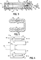
- Figs. 1 to 3 depict an electrical contact 10 which includes a first bifurcated beam 12 and an opposite second bifurcated beam 14. Electrical contact 10 is for use with a conventional blade terminal which may be, without limitation, 0.8 x 2.8 mm.
- Bifurcated beams 12 and 14 are electrically conductive and extend in the direction of a longitudinal axis 16 of the electrical contact 10. Beam 12 is spaced from beam 14 as best depicted in Fig. 3.
- bifurcated beam 12 includes a first fine 18 having a first contact area 20 and bifurcated beam 14 includes an opposite second tine 22 having a second contact area 24.
- contact area 24 is staggered relative to contact area 20 in the direction of longitudinal axis 16.
- bifurcated beam 12 includes a third tine 26 having a third contact area 28 and bifurcated beam 14 includes an opposite fourth tine 30 having a fourth contact area 32 which is staggered relative to contact area 28 in the direction of longitudinal axis 16.
- contact area 24 is also staggered relative to contact area 28 in the direction of longitudinal axis 16.
- bifurcated beams such as beams 12, 14 provides a substantial amount of contact area in the mated condition due to the presence of two tines on each contact surface of the inserted blade terminal. This serves to provide lower interface resistance and therefore a lower temperature rise over a given current.
- the staggering of the tines provides a lower insertion force which may be about 35% less than that required for a nonstaggered configuration.
- Electrical contact 10 also includes a first outer enclosing member 34 which extends in the direction of longitudinal axis 16 adjacent to and spaced from the first bifurcated beam 12 as depicted in Figure 3.
- a second outer enclosing member 36 is provided which extends in the direction of longitudinal axis 16 adjacent to and spaced from the second bifurcated beam 14.
- Outer enclosing members 34 and 36 are electrically conductive.
- the bifurcated beams 12, 14 and the outer enclosing members 34, 36 are joined by an electrically conductive bridging portion 38.
- this is accomplished by fabricating the electrical contact 10 from a blank which has been stamped from an electrically conductive material in a conventional manner. Such stamping operation may produce a blank having a configuration as depicted in solid lines in Figure 4. Subsequent to the stamping operation, the blank 40 may be folded to form the embodiment of Figures 1 to 3. In particular, the bridging portion 38 of blank 40 may be folded along lines 40, 42, thereby folding the outer enclosing members 34, 36 and beams 12, 14, to form a general U-shaped configuration.
- the bridging portion may also be folded along lines 44, 46, thereby folding the bifurcated beams 12, 14, respectively, to a position adjacent to and spaced from respective outer enclosing members 34, 36 as depicted in Figure 3.
- the bifurcated beams 12, 14 form a beam segment 48 having an upper portion 50 enclosed by the outer enclosing member 34, an opposite lower portion 52 enclosed by the outer enclosing member 36, a first open side portion 54 and an opposite second open side portion 56.
- Outer enclosing members 34 and 36 are substantially parallel.
- the open side configuration provided at open side portions 54 and 56 allows for straight-on or pivotal-type mating with a blade terminal and reduces stubbing during insertion of the blade terminal between beams 12, 14.
- Such open side configuration also serves to allow for a more generous positioning of multiple terminals.
- the bridging portion 38 includes an end segment 58 adjacent the bifurcated beam 12 as depicted in Figure 4. Such end segment 58 is in the form of a tag. When the electrical contact 10 is formed, end segment 58 is turned towards and into engagement with a portion 60 of the folded bridging portion 38 adjacent the bifurcated beam 14 as depicted in Figs. 1 to 3. In the embodiment of Figs. 1 to 3 the end segment 58 is adjacent the first line 18 of the bifurcated beam 12 and is turned towards and engages portion 60 adjacent tine 22 of the bifurcated beam 14. End segment 58 serves to maintain separation between outer enclosing member 34 and beam 12, on the one hand, and outer enclosing member 36 and beam 14, on the other.
- bridging portion 38 comprises a first protuberance 62 which is adjacent the bifurcated beam 12 and a second protuberance 64 which is adjacent the bifurcated beam 14 as depicted in Fig. 4.
- protuberances 62 and 64 extend away from the sheet of paper.
- blank 40 is folded as described herein such that protuberance 62 engages folded bridging portion 38 at an area 66 which is adjacent the outer enclosing member 34 to separate outer enclosing member 34 and beam 12, as depicted in Figures 3 and 5.
- blank 40 is folded such that protuberance 64 engages bridging portion 38 at an area 68 which is adjacent the outer enclosing member 36 to separate outer enclosing member 36 and beam 14.
- the tines 18, 22, 26 and 30 are tapered in the direction of longitudinal axis 16, each tine narrowing in a direction from the bridging portion 38 towards opposite end 48 of the bifurcated beams 12, 14.
- the tapered configuration can best be seen in the view of the blank 40 depicted in Figure 4.
- the tapered tines facilitate insertion of the beams 12, 14 through the grommet opening during installation of the electrical contact.
- beams 12, 14 are biased towards each other.
- first contact area 20 and the second contact area 24 are biased towards each other, and the third contact area 28 and the fourth contact area 32 are biased towards each other, as best depicted in Figure 3.
- the ends 70, 72 of respective tines 18, 26 are bent away from the ends 74, 76 of respective tines 22, 30, as best depicted in Figure 3.
- the outer enclosing members 34, 36 serve to protect the beams 12, 14 from damage.
- Members 34, 36 also act as a stress reducer for the beams 12, 14, when mated with a blade terminal 78, and maintain a high normal force between the beams and the blade terminal.
- flexing of respective tines 18, 26 away from lines 22, 30 will be limited by the engagement of tine ends 70,72 with outer enclosing member 34 and the engagement of tine ends 74, 76 with outer enclosing member 36.
- a conductor attachment segment is provided.
- a conductor may be fastened to the conductor attachment segment in a conventional manner as, for example, by soldering and/or crimping or by means of an insulation displacement crimp.
- the conductor attachment segment is depicted in phantom lines 82.
- Such conductor attachment segment may he provided in any configuration suitable for attachment of the conductor to the electrical contact 10.
- the conductor attachment segment 82 will extend away from the electrical contact 10 in the direction of longitudinal axis 16.
- a preferred embodiment is depicted in Fig. 6 in which like reference numerals identify like elements.
- an electrical contact 10' includes a conductor attachment segment 82' which is generally concave in cross-section when viewed in the direction of arrow 84.
- the conductor attachment segment 82' includes a outermost U-shaped length 86, and another U-shaped length 88 adjacent to length 86.
- Lengths 86 and 88 are spaced from each other in the direction of longitudinal axis 16 at 90 and are joined to the bridging portion 38 by a neck portion 92 which extends from the bridging portion to the U-shaped length 88 in the direction of longitudinal axis 16.
- a conductor may be attached to the conductor attachment segment 82' by crimping the legs 94, 96 of lengths 86, 88, respectively, about the conductor in the conventional manner. Solder may be provided at the attachment if desired.
- the conductor attachment segment 82, 82' is integral with the stamped blank used in the fabrication of the electrical contact 10.
Landscapes
- Connector Housings Or Holding Contact Members (AREA)
- Coupling Device And Connection With Printed Circuit (AREA)
Applications Claiming Priority (2)
| Application Number | Priority Date | Filing Date | Title |
|---|---|---|---|
| US08/385,415 US5551897A (en) | 1995-02-08 | 1995-02-08 | Electrical contact |
| US385415 | 1995-02-08 |
Publications (2)
| Publication Number | Publication Date |
|---|---|
| EP0726615A2 true EP0726615A2 (de) | 1996-08-14 |
| EP0726615A3 EP0726615A3 (de) | 1999-07-21 |
Family
ID=23521289
Family Applications (1)
| Application Number | Title | Priority Date | Filing Date |
|---|---|---|---|
| EP96101853A Withdrawn EP0726615A3 (de) | 1995-02-08 | 1996-02-08 | Elektrischer Kontakt |
Country Status (3)
| Country | Link |
|---|---|
| US (1) | US5551897A (de) |
| EP (1) | EP0726615A3 (de) |
| CA (1) | CA2168999A1 (de) |
Cited By (6)
| Publication number | Priority date | Publication date | Assignee | Title |
|---|---|---|---|---|
| EP1255325A1 (de) * | 2001-05-02 | 2002-11-06 | Delphi Technologies, Inc. | Elektrischer Buchsenkontakt |
| WO2002103847A3 (en) * | 2001-06-14 | 2004-02-26 | Tyco Electronics Corp | Multi-beam power contact for an electrical connector |
| FR2857513A1 (fr) * | 2003-07-10 | 2005-01-14 | Bosch Gmbh Robert | Dispositif de contact pour une connexion electrique et outil equipe d'un tel dispositif de contact |
| WO2017089117A1 (de) * | 2015-11-27 | 2017-06-01 | Weidmüller Interface GmbH & Co. KG | Kontaktelement und mehrfachkontakttulpe |
| DE102016108069A1 (de) * | 2016-05-02 | 2017-11-02 | Valeo Systèmes d'Essuyage | Kontaktelement zur Ausbildung einer elektrischen Verbindung mit einem Gegenelement, elektrische Verbindung und Scheibenwischermotor |
| CN112864666A (zh) * | 2021-03-01 | 2021-05-28 | 安费诺(常州)高端连接器有限公司 | 一种防连接器特性退化的互配导引结构、电连接器及电子设备 |
Families Citing this family (19)
| Publication number | Priority date | Publication date | Assignee | Title |
|---|---|---|---|---|
| US5890936A (en) * | 1996-10-15 | 1999-04-06 | Ut Automotive Dearborn, Inc. | Electrical terminal |
| JP2000173703A (ja) * | 1998-12-08 | 2000-06-23 | Yazaki Corp | 電気コンタクト |
| US6217356B1 (en) | 1999-03-30 | 2001-04-17 | The Whitaker Corporation | Electrical terminal with arc arresting region |
| EP1981125B1 (de) * | 2007-04-12 | 2011-06-08 | MTA S.p.A. | Elektrischer Verbinder mit Schwingungsdämpfungsanordnung |
| CH704749B1 (fr) * | 2007-09-05 | 2012-10-15 | Preci Dip Sa | Clip de contact. |
| CN102088136A (zh) * | 2009-12-03 | 2011-06-08 | 泰科电子(上海)有限公司 | 电连接端子 |
| US8721376B1 (en) | 2012-11-01 | 2014-05-13 | Avx Corporation | Single element wire to board connector |
| US20140120786A1 (en) | 2012-11-01 | 2014-05-01 | Avx Corporation | Single element wire to board connector |
| US9391386B2 (en) * | 2014-10-06 | 2016-07-12 | Avx Corporation | Caged poke home contact |
| US9905953B1 (en) | 2016-09-30 | 2018-02-27 | Slobodan Pavlovic | High power spring-actuated electrical connector |
| JP6776085B2 (ja) * | 2016-10-05 | 2020-10-28 | 日本航空電子工業株式会社 | コネクタ |
| US10320096B2 (en) | 2017-06-01 | 2019-06-11 | Avx Corporation | Flexing poke home contact |
| CN111937250B (zh) | 2018-02-26 | 2022-09-30 | 皇家精密制品有限责任公司 | 用于高功率应用的弹簧致动式电连接器 |
| WO2019237009A1 (en) | 2018-06-07 | 2019-12-12 | Royal Precision Products, Llc | Electrical connector system with internal spring component |
| WO2020150399A1 (en) | 2019-01-15 | 2020-07-23 | Royal Precision Products, Llc | Shielded electrical connector system with internal spring component |
| DE112020000459T5 (de) | 2019-01-21 | 2021-11-25 | Royal Precision Products, Llc | Stromverteilungsanordnung mit schraubenlosem sammelschienensystem |
| US11721942B2 (en) | 2019-09-09 | 2023-08-08 | Eaton Intelligent Power Limited | Connector system for a component in a power management system in a motor vehicle |
| CN114787815A (zh) | 2019-09-09 | 2022-07-22 | 伊顿智能动力有限公司 | 具有可读和可记录标记的连接器记录系统 |
| DE112021003695T5 (de) | 2020-07-29 | 2023-06-29 | Eaton Intelligent Power Limited | Verbindersystem einschliesslich eines verriegelungssystems |
Family Cites Families (12)
| Publication number | Priority date | Publication date | Assignee | Title |
|---|---|---|---|---|
| US3862792A (en) * | 1973-10-03 | 1975-01-28 | Gte Sylvania Inc | Electrical connector assembly |
| US4076369A (en) * | 1976-07-26 | 1978-02-28 | Northern Telecom Limited | Box terminal for card edge receptacles in telecommunications systems and the like |
| US4367006A (en) * | 1980-12-10 | 1983-01-04 | Amp Incorporated | Connector for flat cable |
| EP0208888B1 (de) * | 1985-07-03 | 1992-08-12 | Chrysler Corporation | Einschnappender Anschluss mit Drahtführung |
| US4657336A (en) * | 1985-12-18 | 1987-04-14 | Gte Products Corporation | Socket receptacle including overstress protection means for mounting electrical devices on printed circuit boards |
| US4722704A (en) * | 1986-06-12 | 1988-02-02 | Amp Incorporated | High density socket contact receptacle |
| JPS6358776A (ja) * | 1986-08-27 | 1988-03-14 | アンプ インコ−ポレ−テツド | レセプタクルコンタクト |
| FR2621180B1 (fr) * | 1987-09-28 | 1990-01-12 | Francelco Sa | Borne de contact electrique de type cage |
| FR2627020B1 (fr) * | 1988-02-08 | 1994-05-27 | Amp France | Contact electrique destine a recevoir une patte complementaire de connexion |
| CA2018179C (en) * | 1989-06-12 | 2000-04-18 | Norman R. Byrne | Electrical contact arrangement |
| US5281175A (en) * | 1993-03-30 | 1994-01-25 | General Motors Corporation | Female electrical terminal |
| FR2714220B3 (fr) * | 1993-12-16 | 1996-04-26 | Matra Communication | Contact électrique à souder et ensemble de réception de haut-parleur en faisant application. |
-
1995
- 1995-02-08 US US08/385,415 patent/US5551897A/en not_active Expired - Fee Related
-
1996
- 1996-02-07 CA CA002168999A patent/CA2168999A1/en not_active Abandoned
- 1996-02-08 EP EP96101853A patent/EP0726615A3/de not_active Withdrawn
Cited By (12)
| Publication number | Priority date | Publication date | Assignee | Title |
|---|---|---|---|---|
| EP1255325A1 (de) * | 2001-05-02 | 2002-11-06 | Delphi Technologies, Inc. | Elektrischer Buchsenkontakt |
| WO2002103847A3 (en) * | 2001-06-14 | 2004-02-26 | Tyco Electronics Corp | Multi-beam power contact for an electrical connector |
| US6776635B2 (en) | 2001-06-14 | 2004-08-17 | Tyco Electronics Corporation | Multi-beam power contact for an electrical connector |
| FR2857513A1 (fr) * | 2003-07-10 | 2005-01-14 | Bosch Gmbh Robert | Dispositif de contact pour une connexion electrique et outil equipe d'un tel dispositif de contact |
| GB2404793A (en) * | 2003-07-10 | 2005-02-09 | Bosch Gmbh Robert | Contact arrangement in the case of an electrical plug-in connection |
| WO2017089117A1 (de) * | 2015-11-27 | 2017-06-01 | Weidmüller Interface GmbH & Co. KG | Kontaktelement und mehrfachkontakttulpe |
| CN108370111A (zh) * | 2015-11-27 | 2018-08-03 | 威德米勒界面有限公司及两合公司 | 接触元件和多触点连接器 |
| JP2018535527A (ja) * | 2015-11-27 | 2018-11-29 | ヴァイトミュラー インターフェイス ゲゼルシャフト ミット ベシュレンクテル ハフツング ウント コンパニー コマンデイトゲゼルシャフト | 接触要素及び多重接触チューリップ |
| US10411382B2 (en) | 2015-11-27 | 2019-09-10 | Weidmüller Interface GmbH & Co. KG | Contact element and multiple contact assembly |
| CN108370111B (zh) * | 2015-11-27 | 2020-04-24 | 威德米勒界面有限公司及两合公司 | 接触元件和多触点连接器 |
| DE102016108069A1 (de) * | 2016-05-02 | 2017-11-02 | Valeo Systèmes d'Essuyage | Kontaktelement zur Ausbildung einer elektrischen Verbindung mit einem Gegenelement, elektrische Verbindung und Scheibenwischermotor |
| CN112864666A (zh) * | 2021-03-01 | 2021-05-28 | 安费诺(常州)高端连接器有限公司 | 一种防连接器特性退化的互配导引结构、电连接器及电子设备 |
Also Published As
| Publication number | Publication date |
|---|---|
| US5551897A (en) | 1996-09-03 |
| CA2168999A1 (en) | 1996-08-09 |
| EP0726615A3 (de) | 1999-07-21 |
Similar Documents
| Publication | Publication Date | Title |
|---|---|---|
| US5551897A (en) | Electrical contact | |
| US6062919A (en) | Electrical connector assembly having high current-carrying capability and low insertion force | |
| KR100503824B1 (ko) | 원피스콘택스프링 | |
| US5207603A (en) | Dual thickness blade type electrical terminal | |
| US5911605A (en) | Universal terminal connection | |
| US6551129B2 (en) | Ground connector | |
| EP0795930B1 (de) | Elektrische Aufnahmebuchse für Stift mit hoher Kontaktkraft | |
| EP0569064B1 (de) | Elektrischer Hülsenanschluss | |
| US3123431A (en) | Electrical connector | |
| US5462459A (en) | Spring-type electrical receptacle | |
| EP0952631B1 (de) | Kontaktstift | |
| EP0673078B1 (de) | Schneidklemmkontakt | |
| JP3315870B2 (ja) | 圧接端子 | |
| EP0676827A2 (de) | Elektrischer Kontakt mit verbesserten zweiten Verriegelungsflächen | |
| US6004171A (en) | Crimp-type terminal | |
| EP0649186B1 (de) | Elektrische Anschlussklemme zum Aufpressen an einen Leiter | |
| US6483035B2 (en) | Protecting configuration for flat cables | |
| US6309244B1 (en) | Connector assembly and power shunt contact | |
| EP1089387A2 (de) | Modulare elektrische Anschlussbuchse | |
| IE49732B1 (en) | Insulation-displacement connector | |
| US20020055297A1 (en) | Modular female electrical terminal | |
| GB2111768A (en) | Electrical contact receptacle | |
| EP2183822B1 (de) | Elektrischer kontakt | |
| EP1049218A3 (de) | Elektrischer Verbinder mit geringer Breite | |
| US5591044A (en) | Press-connecting terminal |
Legal Events
| Date | Code | Title | Description |
|---|---|---|---|
| PUAI | Public reference made under article 153(3) epc to a published international application that has entered the european phase |
Free format text: ORIGINAL CODE: 0009012 |
|
| AK | Designated contracting states |
Kind code of ref document: A2 Designated state(s): BE DE FR GB NL |
|
| PUAL | Search report despatched |
Free format text: ORIGINAL CODE: 0009013 |
|
| AK | Designated contracting states |
Kind code of ref document: A3 Designated state(s): BE DE FR GB NL |
|
| 17P | Request for examination filed |
Effective date: 20000117 |
|
| STAA | Information on the status of an ep patent application or granted ep patent |
Free format text: STATUS: THE APPLICATION IS DEEMED TO BE WITHDRAWN |
|
| 18D | Application deemed to be withdrawn |
Effective date: 20010829 |