EP0726622A2 - Dispositif de distribution électrique - Google Patents
Dispositif de distribution électrique Download PDFInfo
- Publication number
- EP0726622A2 EP0726622A2 EP96100304A EP96100304A EP0726622A2 EP 0726622 A2 EP0726622 A2 EP 0726622A2 EP 96100304 A EP96100304 A EP 96100304A EP 96100304 A EP96100304 A EP 96100304A EP 0726622 A2 EP0726622 A2 EP 0726622A2
- Authority
- EP
- European Patent Office
- Prior art keywords
- plug
- connector
- connectors
- pole
- conductor
- Prior art date
- Legal status (The legal status is an assumption and is not a legal conclusion. Google has not performed a legal analysis and makes no representation as to the accuracy of the status listed.)
- Granted
Links
Images

Classifications
-
- H—ELECTRICITY
- H01—ELECTRIC ELEMENTS
- H01R—ELECTRICALLY-CONDUCTIVE CONNECTIONS; STRUCTURAL ASSOCIATIONS OF A PLURALITY OF MUTUALLY-INSULATED ELECTRICAL CONNECTING ELEMENTS; COUPLING DEVICES; CURRENT COLLECTORS
- H01R9/00—Structural associations of a plurality of mutually-insulated electrical connecting elements, e.g. terminal strips or terminal blocks; Terminals or binding posts mounted upon a base or in a case; Bases therefor
- H01R9/22—Bases, e.g. strip, block, panel
- H01R9/24—Terminal blocks
- H01R9/26—Clip-on terminal blocks for side-by-side rail- or strip-mounting
-
- H—ELECTRICITY
- H01—ELECTRIC ELEMENTS
- H01R—ELECTRICALLY-CONDUCTIVE CONNECTIONS; STRUCTURAL ASSOCIATIONS OF A PLURALITY OF MUTUALLY-INSULATED ELECTRICAL CONNECTING ELEMENTS; COUPLING DEVICES; CURRENT COLLECTORS
- H01R31/00—Coupling parts supported only by co-operation with counterpart
- H01R31/02—Intermediate parts for distributing energy to two or more circuits in parallel, e.g. splitter
-
- H—ELECTRICITY
- H01—ELECTRIC ELEMENTS
- H01R—ELECTRICALLY-CONDUCTIVE CONNECTIONS; STRUCTURAL ASSOCIATIONS OF A PLURALITY OF MUTUALLY-INSULATED ELECTRICAL CONNECTING ELEMENTS; COUPLING DEVICES; CURRENT COLLECTORS
- H01R4/00—Electrically-conductive connections between two or more conductive members in direct contact, i.e. touching one another; Means for effecting or maintaining such contact; Electrically-conductive connections having two or more spaced connecting locations for conductors and using contact members penetrating insulation
- H01R4/28—Clamped connections, spring connections
- H01R4/48—Clamped connections, spring connections utilising a spring, clip, or other resilient member
- H01R4/4809—Clamped connections, spring connections utilising a spring, clip, or other resilient member using a leaf spring to bias the conductor toward the busbar
- H01R4/4846—Busbar details
-
- H—ELECTRICITY
- H01—ELECTRIC ELEMENTS
- H01R—ELECTRICALLY-CONDUCTIVE CONNECTIONS; STRUCTURAL ASSOCIATIONS OF A PLURALITY OF MUTUALLY-INSULATED ELECTRICAL CONNECTING ELEMENTS; COUPLING DEVICES; CURRENT COLLECTORS
- H01R9/00—Structural associations of a plurality of mutually-insulated electrical connecting elements, e.g. terminal strips or terminal blocks; Terminals or binding posts mounted upon a base or in a case; Bases therefor
- H01R9/22—Bases, e.g. strip, block, panel
- H01R9/24—Terminal blocks
- H01R9/2491—Terminal blocks structurally associated with plugs or sockets
-
- H—ELECTRICITY
- H01—ELECTRIC ELEMENTS
- H01R—ELECTRICALLY-CONDUCTIVE CONNECTIONS; STRUCTURAL ASSOCIATIONS OF A PLURALITY OF MUTUALLY-INSULATED ELECTRICAL CONNECTING ELEMENTS; COUPLING DEVICES; CURRENT COLLECTORS
- H01R4/00—Electrically-conductive connections between two or more conductive members in direct contact, i.e. touching one another; Means for effecting or maintaining such contact; Electrically-conductive connections having two or more spaced connecting locations for conductors and using contact members penetrating insulation
- H01R4/28—Clamped connections, spring connections
- H01R4/48—Clamped connections, spring connections utilising a spring, clip, or other resilient member
- H01R4/4809—Clamped connections, spring connections utilising a spring, clip, or other resilient member using a leaf spring to bias the conductor toward the busbar
- H01R4/4811—Spring details
- H01R4/4816—Spring details the spring shape preventing insertion of the conductor end when the spring is unbiased
-
- H—ELECTRICITY
- H01—ELECTRIC ELEMENTS
- H01R—ELECTRICALLY-CONDUCTIVE CONNECTIONS; STRUCTURAL ASSOCIATIONS OF A PLURALITY OF MUTUALLY-INSULATED ELECTRICAL CONNECTING ELEMENTS; COUPLING DEVICES; CURRENT COLLECTORS
- H01R4/00—Electrically-conductive connections between two or more conductive members in direct contact, i.e. touching one another; Means for effecting or maintaining such contact; Electrically-conductive connections having two or more spaced connecting locations for conductors and using contact members penetrating insulation
- H01R4/28—Clamped connections, spring connections
- H01R4/48—Clamped connections, spring connections utilising a spring, clip, or other resilient member
- H01R4/4809—Clamped connections, spring connections utilising a spring, clip, or other resilient member using a leaf spring to bias the conductor toward the busbar
- H01R4/484—Spring housing details
- H01R4/4842—Spring housing details the spring housing being provided with a single opening for insertion of a spring-activating tool
Definitions
- the present invention relates to an electrical distributor arrangement for distributing electrical power. It is known, for example, in a connector for electrical bus conductors (DE 94 10 614 U1), the electrical connectors from a multipole connector strip with one or more connection elements for each pole for incoming and outgoing conductor ends that are electrically connected to one another by a connector to assign an electrical connector element for a corresponding connector element on the system side, so that after loosening the plug connection the system is switched off from the power supply, but the electrical connection between the incoming and outgoing end of the bus conductor is maintained.
- the connector thus acts in the manner of a connector.
- the present invention is based on the object of creating an electrical distributor arrangement which, with a minimal wiring expenditure and very small space requirement, ensures a simple possibility of multiple branching of a supplied electrical power of an invariable configuration.
- the solution according to the invention essentially consists in an electrical distributor arrangement with a multi-pole connector for the power supply and a plurality of multi-pin connectors for power tapping, each with conductor connections and thus connectors connected via busbar pieces in accordance with the number of poles and also with a multi-pin, disk-shaped distribution block, in the disks of which connectors for the respective connectors of the connector plugs are provided, which are electrically connected to one another by busbar pieces are, in the multi-pole terminal blocks and their busbar plug receptacles for electrical cross connectors are provided and the connector for the power supply is wired to only one pole with an incoming conductor and from this conductor connection the power is distributed to the other poles of the connector via a plug cross connector is.
- the power split is also extremely variable and expandable. If, for example, several consumers are added for an affected connector, simple connection disks can be attached to the distributor block without a plug connection and power can be supplied to it via an inserted cross connector. A further power cross-distribution can also take place on connector strips or the like via the cross connector, which are without their own plug connection option to the distribution block, but to which further consumers can then be connected.
- cross connector for one or more connecting plugs is designed as a separating plug, so that individual current paths in the poles of the connecting plugs can be separated with this separating plug, while other functions of the other current paths can be retained. This leads to a particularly large extent to targeted shutdowns for testing and maintenance purposes while maintaining functions that are not affected by it to a particularly large extent.
- a plug-in receptacle for a cross connector is also provided in the distributor block constructed from disks, with which the busbar pieces of individual disks, in particular also an adjacent distributor block, can be electrically connected, so that a further power distribution option is additionally created in the area of the distributor block .
- a distributor block 1 is provided as the central distributor element, which is composed of a plurality of individual disks, one of which can be seen in a side view in FIG. 1.
- the baying of the panes extends to the drawing, for example, in their depth.
- the four connectors 3, 4 are mutually electrically conductive in each disk by an essentially U- shaped, branched busbar piece 5 electrically connected together.
- the pin-shaped plug connector 4 can be fixed in the disk housing 2 with the aid of separate plastic inserts 6.
- the distributor block 1 can have a latching foot arrangement 7 in its entirety, so that it can be latched overall, for example, on a mounting rail.
- a total of four connectors 8, 9, 10 are provided for electrical and mechanical plug connection with the distributor block 1, which are also multi-pole.
- the connector 8 is used to supply power.
- the connector 8 has two conductor connections 11 per pole, which are connected in an electrically conductive manner by a busbar 12 to the connector 3 in this case, which is socket-shaped.
- the busbar 12 has an upward-pointing bend 13, from the upper end of which a further bend 14 extends, in which there is the plug-in opening for a cross connector 15, for the upper continuous cross-bar of which the rows of poles of the housing of the connector plug 8 are arranged there is a plug-in opening, corresponding plug-in openings for the individual comb-like tines 16 of the cross connector 15 being provided in the individual poles in the housing.
- this connector 8 for the power supply is only wired to one pole with its conductor connection 11 to an incoming electrical conductor 17.
- all conductor connections 11 are shown as clamping spring connections.
- the power in the connector 8 is distributed over the plugged cross connector 15 to the conductor rails 12 of the other poles. All busbars 12 are firmly connected to a connector 18, which in this case is socket-shaped. Due to the described bends 13, 14 of the busbar 12 with the plug-in opening for the cross connector 15, 16, this power transmission zone between the busbar 12 and the connector 18 can thus be kept on the full power transmission cross-section to this extent without opening or the like. Due to the arrangement described, the power distribution in the connector 8 is thus also carried out on all of its connectors 18.
- the power distribution takes place in the distributor block 1 on its conductor rail pieces 5 in the individual poles and there to the other connectors 3, 4 in the distributor block 1 and is available there for tapping through the further connecting plugs 9, 10, which are used for power tapping and power distribution to the consumers.
- a connector 9 is provided for the power tap, which is structurally identical to the connector 8 described above, so that reference can be made to the above description.
- the two conductor connections 11 in the connector 9 per pole can be wired to outgoing conductors 19 leading to corresponding consumers.
- the cross connector 15 can be inserted in order to carry out a further transverse distribution of the power starting from the connector 9 to neighboring connectors, terminal strips or the like, which then do not have to have their own plug connection to the distributor block 1. In this way, even when the system is expanded or expanded, connecting disks to be attached to the connector plug 9 can be easily connected to power without a separate plug connection to the distributor block.
- two further connectors 10 are provided for the power tap, which are also multi-pole and resemble the connectors 8, 9 in the basic structure.
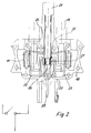
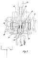
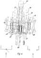
- Various configurations in this regard are shown in detail in particular in FIGS. 2-4.
- a pole of a multipole connector 10 is shown, in which only the conductor connection 11 seen on the right of the drawing is directly and firmly connected in an electrically conductive manner to the connector 20, which is in the form of a pin, by means of a separate connecting strap 22.
- the elements of the divided busbar 23 have, moreover, at their ends facing away from the conductor connections 11 upward bends 24, the bends 24 of the two busbar parts 23 being spaced apart and thus forming a plug opening 25 into which one of the comb-like in this pole Prongs 26 of the isolating plug 21 can be inserted.
- the comb-like tines 26 have a relatively short, electrically conductive section 27, which, after being contacted by being inserted into the plug-in opening 25, conductively connects the two busbar parts 23 to one another. If the isolating plug 21 is pulled in this embodiment, the conductor connections 11, seen on the drawing of the right side of the multipole connector 10, remain in conductive connection with the power supply, if this were only interrupted to the conductor connections 11 lying on the drawing on the left side, that is to say only these corresponding current paths are switched off. This is symbolically outlined in FIG. 2.
- FIG. 3 illustrates a similar operation with the same basic structure.
- the left busbar part 23 is permanently connected to the connecting tab 22 with the pin-shaped connector 20, so that after pulling the isolating plug 21, the left-hand conductor connections 11 of the power supply now remain, while the right-hand conductor connections 11 and thus the corresponding current paths are separated are, as outlined in connection with Figure 3 also.
- FIG. 4 Another possible embodiment is illustrated in FIG. 4.
- the prongs 26 'of the isolating plug 21' have a relatively long conductive section 27 '.
- the two busbar parts 23 ', which lead to the conductor connections 11, do not have their own direct and direct connection to the plug connector 20, and a corresponding connecting tab 22 is therefore missing.
- the plug connector 20 is fixed in the form of a socket Connecting piece 22 'connected, into which the lower end region of the prongs 26' of the isolating plug 21 'can also be inserted with a still conductive section region.
- This configuration enables two different circuit states, as outlined in FIG. 4.
Landscapes
- Connector Housings Or Holding Contact Members (AREA)
- Internal Circuitry In Semiconductor Integrated Circuit Devices (AREA)
- Non-Reversible Transmitting Devices (AREA)
- Details Of Connecting Devices For Male And Female Coupling (AREA)
- Electrical Discharge Machining, Electrochemical Machining, And Combined Machining (AREA)
- Discharge Of Articles From Conveyors (AREA)
- Coupling Device And Connection With Printed Circuit (AREA)
Applications Claiming Priority (2)
| Application Number | Priority Date | Filing Date | Title |
|---|---|---|---|
| DE29502186U | 1995-02-10 | ||
| DE29502186U DE29502186U1 (de) | 1995-02-10 | 1995-02-10 | Elektrische Verteileranordnung |
Publications (3)
| Publication Number | Publication Date |
|---|---|
| EP0726622A2 true EP0726622A2 (fr) | 1996-08-14 |
| EP0726622A3 EP0726622A3 (fr) | 1997-09-10 |
| EP0726622B1 EP0726622B1 (fr) | 2001-10-24 |
Family
ID=8003725
Family Applications (1)
| Application Number | Title | Priority Date | Filing Date |
|---|---|---|---|
| EP96100304A Expired - Lifetime EP0726622B1 (fr) | 1995-02-10 | 1996-01-11 | Dispositif de distribution électrique |
Country Status (5)
| Country | Link |
|---|---|
| US (1) | US5658172A (fr) |
| EP (1) | EP0726622B1 (fr) |
| AT (1) | ATE207661T1 (fr) |
| DE (2) | DE29502186U1 (fr) |
| ES (1) | ES2161923T3 (fr) |
Cited By (4)
| Publication number | Priority date | Publication date | Assignee | Title |
|---|---|---|---|---|
| DE29921080U1 (de) * | 1999-12-01 | 2001-04-12 | Weidmüller Interface GmbH & Co, 32760 Detmold | Reihenklemme, insbesondere Wandlerklemme, mit einer Querbrückungsvorrichtung |
| EP1189307A3 (fr) * | 2000-09-13 | 2002-07-31 | PHOENIX CONTACT GmbH & Co. Kg | Barrette à bornes electrique |
| WO2013037490A1 (fr) * | 2011-09-15 | 2013-03-21 | Phoenix Contact Gmbh & Co. Kg | Borne serre-fils électrique et bloc de bornes serre-fils électriques |
| US12119597B2 (en) | 2022-05-19 | 2024-10-15 | James Brown | Electrical junction box assembly |
Families Citing this family (32)
| Publication number | Priority date | Publication date | Assignee | Title |
|---|---|---|---|---|
| DE29613738U1 (de) * | 1996-08-08 | 1996-09-19 | Weidmüller Interface GmbH & Co, 32760 Detmold | Stromschiene für Reihenklemmen, Klemmverbinder u.dgl. |
| FR2757316B1 (fr) * | 1996-12-16 | 1999-01-22 | Entrelec Sa | Module de raccordement a bornes de connexion interconnectables par piece(s) conductrice(s) mobile(s) |
| DE19727454B4 (de) * | 1997-06-27 | 2006-09-21 | The Whitaker Corp., Wilmington | Anordnung zur lösbaren Befestigung an einer Schiene |
| US5890934A (en) * | 1997-09-30 | 1999-04-06 | Weidmuller Inc. | Pluggable connector assembly for printed circuit boards |
| IT1296132B1 (it) * | 1997-11-12 | 1999-06-09 | Cogip Srl | Unita' di interconnessione e ridistribuzione per il collegamento di circuiti elettrici ed elettronici di comando a bordo di macchine |
| DE19964157A1 (de) * | 1999-01-25 | 2000-10-05 | Weidmueller Interface | Elektrisches Gerät |
| DE10054260A1 (de) * | 2000-11-02 | 2002-05-29 | Vera Feistkorn | Verbindungsvorrichtung für elektrische Leiter zum Auflöten auf Platinen |
| DE20205594U1 (de) * | 2002-04-10 | 2003-08-28 | Weidmüller Interface GmbH & Co., 32760 Detmold | Anschlußvorrichtung zum Anschluß von Daten- und Versorgungsleitungen an ein elektrisches Gerät |
| US7101231B2 (en) | 2003-10-09 | 2006-09-05 | Cooper Technologies Company | Locking spring-clamp terminal block and method for connecting the same |
| DE10348088B3 (de) * | 2003-10-16 | 2005-01-20 | Moeller Gmbh | Schaltschütz mit Rahmenklemmen |
| DE102005003199A1 (de) * | 2004-08-24 | 2006-03-02 | Weidmüller Interface GmbH & Co. KG | Montage- und Anschluß-System für elektrische Geräte |
| US7548412B2 (en) * | 2005-01-27 | 2009-06-16 | Cooper Technologies Company | Switchable fused power distribution block |
| DE202005013056U1 (de) * | 2005-08-18 | 2007-01-04 | Weidmüller Interface GmbH & Co. KG | Elektrische Anschlussvorrichtung |
| DE102005040657A1 (de) * | 2005-08-26 | 2007-03-15 | Phoenix Contact Gmbh & Co. Kg | Elektrische Anschlussklemme |
| DE202006006626U1 (de) * | 2006-04-26 | 2007-09-06 | Weidmüller Interface GmbH & Co. KG | Verbindungs- und Schaltvorrichtung |
| ATE449438T1 (de) * | 2006-06-27 | 2009-12-15 | Weidmueller Interface | Verbindungs- und schaltvorrichtung |
| DE202006017882U1 (de) * | 2006-11-22 | 2007-03-01 | Cedes Ag | Steckmodul |
| DE202007005373U1 (de) * | 2007-04-12 | 2008-08-21 | Weidmüller Interface GmbH & Co. KG | Reihenklemmensystem |
| DE102009004136B4 (de) * | 2009-01-06 | 2011-09-01 | Phoenix Contact Gmbh & Co. Kg | Elektrische Anschlussklemme zum Durchführen einer Leitung durch eine Wandung |
| DE102012206600A1 (de) * | 2012-04-20 | 2013-10-24 | Wöhner GmbH & Co. KG Elektrotechnische Systeme | Tragschienenadapter |
| DE102012107264A1 (de) * | 2012-08-08 | 2014-02-13 | Phoenix Contact Gmbh & Co. Kg | Anschlussmodul |
| DE102012017429B4 (de) * | 2012-09-04 | 2018-11-22 | Phoenix Contact Gmbh & Co. Kg | Prüfklemmenblock und Baugruppe aus einer Befestigungsklemme und einem Befestigungsteil |
| PL3054533T3 (pl) | 2015-02-05 | 2020-06-29 | Morsettitalia S.P.A. | Podstawowa listwa zaciskowa i pomocnicza listwa zaciskowa do tablic rozdzielczych oraz dwupoziomowy zespół listwy zaciskowej zawierający podstawową listwę zaciskową i pomocniczą listwę zaciskową |
| DE102015102257B4 (de) * | 2015-02-17 | 2017-08-24 | Phoenix Contact Gmbh & Co. Kg | Elektrische Reihenklemme und Steckersystem für Reihenklemmen mit einem Betriebs- oder Prüfstecker |
| US9396889B1 (en) * | 2015-04-03 | 2016-07-19 | Eaton Corporation | Electrical switching apparatus and secondary disconnect assembly with cradle assembly alignment and positioning features therefor |
| PL3288131T3 (pl) * | 2016-08-24 | 2020-11-30 | Anord Mardix Databar Busway Limited | System przewodów szynowych |
| JP6644754B2 (ja) * | 2017-11-07 | 2020-02-12 | 矢崎総業株式会社 | 雌端子、および、導通検査装置 |
| DE102018109861A1 (de) * | 2018-04-24 | 2019-10-24 | Phoenix Contact Gmbh & Co. Kg | Steckverbindungsanordnung für eine Reihenklemme |
| BE1026735B1 (de) * | 2018-10-30 | 2020-06-02 | Phoenix Contact Gmbh & Co | Elektrische Reihenklemme |
| FR3088493B1 (fr) * | 2018-11-12 | 2022-05-13 | Schneider Electric Ind Sas | Dispositif de raccordement electrique des bornes aval d'un appareil de protection electrique |
| DE202018106978U1 (de) * | 2018-12-06 | 2020-03-09 | Weidmüller Interface GmbH & Co. KG | Kupplungsblock für Steckverbinder |
| FR3126821A1 (fr) * | 2021-09-09 | 2023-03-10 | Schneider Electric Industries Sas | Distributeur de courant électrique et tableau électrique |
Family Cites Families (14)
| Publication number | Priority date | Publication date | Assignee | Title |
|---|---|---|---|---|
| GB1197146A (en) * | 1968-05-13 | 1970-07-01 | Isaburo Takeyasu | Plate bending Jig |
| DE3048497C2 (de) * | 1980-12-22 | 1982-10-07 | C.A. Weidmüller KG, 4930 Detmold | Querverbinder für Reihenklemmen |
| DE3571177D1 (de) * | 1985-11-09 | 1989-07-27 | Weidmueller C A Gmbh Co | Initiator terminal block |
| DE3624081A1 (de) * | 1986-07-17 | 1988-01-21 | Quante Fernmeldetechnik Gmbh | Ueberspannungsschutz-reihenklemme |
| DE3805158A1 (de) * | 1988-02-15 | 1989-08-24 | Wago Verwaltungs Gmbh | Reihenklemme zur zweileiter-stromversorgung von elektrischen oder elektronischen bauelementen, insbesondere initiatoren |
| FR2636782B1 (fr) | 1988-09-16 | 1991-05-24 | Merlin Gerin | Dispositif de raccordement par peigne de pontage d'appareils electriques modulaires, et procede de fabrication d'un tel peigne |
| DE58905551D1 (de) * | 1989-03-04 | 1993-10-14 | Weidmueller Interface | Doppeltrennklemme. |
| EP0396808B1 (fr) * | 1989-05-12 | 1994-09-28 | Weidmüller Interface GmbH & Co. | Dispositif de bornes en rangée |
| DE4015689C2 (de) * | 1990-05-16 | 1994-03-10 | Elco Europ Gmbh | Vorrichtung zur Halterung elektrotechnischer, insbesondere nachrichtentechnischer Bauteile |
| JP2601848Y2 (ja) * | 1992-01-10 | 1999-12-06 | 住友電装株式会社 | ジョイントボックス |
| DE9203970U1 (de) * | 1992-03-25 | 1992-05-07 | Weidmüller Interface GmbH & Co., 4930 Detmold | Schutzleiterreihenklemme |
| DE9302091U1 (de) * | 1993-02-13 | 1993-04-22 | HTS-Elektrotechnik GmbH, 5206 Neunkirchen-Seelscheid | Vielpoliger Steckereinsatz |
| DE4322535C2 (de) * | 1993-07-02 | 2003-03-13 | Wago Verwaltungs Gmbh | Elektrische Klemmen mit steckbaren Querbrückern |
| DE9410614U1 (de) * | 1994-07-01 | 1994-08-11 | Weidmüller Interface GmbH & Co, 32760 Detmold | Verbinder für elektrische Bus-Leiter |
-
1995
- 1995-02-10 DE DE29502186U patent/DE29502186U1/de not_active Expired - Lifetime
-
1996
- 1996-01-11 DE DE59607967T patent/DE59607967D1/de not_active Expired - Lifetime
- 1996-01-11 EP EP96100304A patent/EP0726622B1/fr not_active Expired - Lifetime
- 1996-01-11 AT AT96100304T patent/ATE207661T1/de not_active IP Right Cessation
- 1996-01-11 ES ES96100304T patent/ES2161923T3/es not_active Expired - Lifetime
- 1996-02-07 US US08/598,219 patent/US5658172A/en not_active Expired - Lifetime
Cited By (5)
| Publication number | Priority date | Publication date | Assignee | Title |
|---|---|---|---|---|
| DE29921080U1 (de) * | 1999-12-01 | 2001-04-12 | Weidmüller Interface GmbH & Co, 32760 Detmold | Reihenklemme, insbesondere Wandlerklemme, mit einer Querbrückungsvorrichtung |
| EP1189307A3 (fr) * | 2000-09-13 | 2002-07-31 | PHOENIX CONTACT GmbH & Co. Kg | Barrette à bornes electrique |
| WO2013037490A1 (fr) * | 2011-09-15 | 2013-03-21 | Phoenix Contact Gmbh & Co. Kg | Borne serre-fils électrique et bloc de bornes serre-fils électriques |
| EA029201B1 (ru) * | 2011-09-15 | 2018-02-28 | Фёникс Контакт Гмбх Унд Ко. Кг | Электрический присоединительный зажим и блок присоединительных зажимов |
| US12119597B2 (en) | 2022-05-19 | 2024-10-15 | James Brown | Electrical junction box assembly |
Also Published As
| Publication number | Publication date |
|---|---|
| DE59607967D1 (de) | 2001-11-29 |
| ATE207661T1 (de) | 2001-11-15 |
| EP0726622B1 (fr) | 2001-10-24 |
| US5658172A (en) | 1997-08-19 |
| ES2161923T3 (es) | 2001-12-16 |
| EP0726622A3 (fr) | 1997-09-10 |
| DE29502186U1 (de) | 1995-03-30 |
Similar Documents
| Publication | Publication Date | Title |
|---|---|---|
| EP0726622B1 (fr) | Dispositif de distribution électrique | |
| EP0709921B1 (fr) | Barrette d'interconnexion pour repartition transversale de puissance | |
| EP2255410B1 (fr) | Barrette a bornes ou bloc de barrettes a bornes | |
| DE4438800C1 (de) | Anschlußklemmenblock mit Elektronikmodul | |
| EP2756554A1 (fr) | Borne serre-fils électrique et bloc de bornes serre-fils électriques | |
| DE102005040348B4 (de) | Verbindungssystem mit einem elektromagnetischem Schaltgerät, insbesondere Schütz, und einem Stecker | |
| DE10156214B4 (de) | Mehrphasiges Sammelschienensystem | |
| DE2335361A1 (de) | Elektrische verbindungsvorrichtung | |
| DE19902745A1 (de) | Elektrisches Gerät | |
| EP1113525B1 (fr) | Barette à bornes, en particulier pour transformateur de mesure avec dispositif de pontage transversal | |
| DE29514711U1 (de) | Reihenklemmenanordnung | |
| EP2561585B1 (fr) | Dispositif de raccordement à connexion électrique variable entre raccordements de conducteurs | |
| DE19603960A1 (de) | Mehrpoliger Abzweig-Steckverbinder | |
| EP0709919A1 (fr) | Barrette d'interconnexion pour repartition transversale de puissance | |
| EP0634813B1 (fr) | Bloc de distribution | |
| EP0952635B1 (fr) | Connecteur électrique | |
| DE69931742T2 (de) | Elektrisches Gerät wie ein Leistungsschalter oder ein moduläre Schalter | |
| EP0222030A1 (fr) | Bloc de connexion pour initiateur | |
| EP0921611B1 (fr) | Prise et interrupteur pour le secteur | |
| BE1026787B1 (de) | Anschlussvorrichtung für elektrische Leiter | |
| EP1472766A1 (fr) | Dispositif de raccordement ou de distribution pour appareils electriques d'installation | |
| DE202007013483U1 (de) | Verbindungsklemmenblock für elektrische Mehrphasenmotoren | |
| EP2251944B1 (fr) | Connecteur transversal pour des commutateurs série sur un organe de support | |
| DE19534690B4 (de) | Abgangskasten für Schienenverteiler | |
| DE4139081C1 (en) | Electrical strip terminal connector - has additional recess(es) for further collector rail(s) connectable to common current bar via screw |
Legal Events
| Date | Code | Title | Description |
|---|---|---|---|
| PUAI | Public reference made under article 153(3) epc to a published international application that has entered the european phase |
Free format text: ORIGINAL CODE: 0009012 |
|
| AK | Designated contracting states |
Kind code of ref document: A2 Designated state(s): AT CH DE ES FR GB IT LI |
|
| PUAL | Search report despatched |
Free format text: ORIGINAL CODE: 0009013 |
|
| AK | Designated contracting states |
Kind code of ref document: A3 Designated state(s): AT CH DE ES FR GB IT LI |
|
| 17P | Request for examination filed |
Effective date: 19970927 |
|
| 17Q | First examination report despatched |
Effective date: 20000114 |
|
| GRAG | Despatch of communication of intention to grant |
Free format text: ORIGINAL CODE: EPIDOS AGRA |
|
| GRAG | Despatch of communication of intention to grant |
Free format text: ORIGINAL CODE: EPIDOS AGRA |
|
| GRAH | Despatch of communication of intention to grant a patent |
Free format text: ORIGINAL CODE: EPIDOS IGRA |
|
| GRAH | Despatch of communication of intention to grant a patent |
Free format text: ORIGINAL CODE: EPIDOS IGRA |
|
| GRAA | (expected) grant |
Free format text: ORIGINAL CODE: 0009210 |
|
| AK | Designated contracting states |
Kind code of ref document: B1 Designated state(s): AT CH DE ES FR GB IT LI |
|
| REF | Corresponds to: |
Ref document number: 207661 Country of ref document: AT Date of ref document: 20011115 Kind code of ref document: T |
|
| REG | Reference to a national code |
Ref country code: CH Ref legal event code: NV Representative=s name: ISLER & PEDRAZZINI AG Ref country code: CH Ref legal event code: EP |
|
| REF | Corresponds to: |
Ref document number: 59607967 Country of ref document: DE Date of ref document: 20011129 |
|
| REG | Reference to a national code |
Ref country code: ES Ref legal event code: FG2A Ref document number: 2161923 Country of ref document: ES Kind code of ref document: T3 |
|
| REG | Reference to a national code |
Ref country code: GB Ref legal event code: IF02 |
|
| GBT | Gb: translation of ep patent filed (gb section 77(6)(a)/1977) |
Effective date: 20020115 |
|
| ET | Fr: translation filed | ||
| PLBE | No opposition filed within time limit |
Free format text: ORIGINAL CODE: 0009261 |
|
| STAA | Information on the status of an ep patent application or granted ep patent |
Free format text: STATUS: NO OPPOSITION FILED WITHIN TIME LIMIT |
|
| 26N | No opposition filed | ||
| REG | Reference to a national code |
Ref country code: CH Ref legal event code: PCAR Free format text: ISLER & PEDRAZZINI AG;POSTFACH 1772;8027 ZUERICH (CH) |
|
| PGFP | Annual fee paid to national office [announced via postgrant information from national office to epo] |
Ref country code: ES Payment date: 20090122 Year of fee payment: 14 Ref country code: AT Payment date: 20090115 Year of fee payment: 14 |
|
| PGFP | Annual fee paid to national office [announced via postgrant information from national office to epo] |
Ref country code: GB Payment date: 20090122 Year of fee payment: 14 Ref country code: CH Payment date: 20090115 Year of fee payment: 14 |
|
| PGFP | Annual fee paid to national office [announced via postgrant information from national office to epo] |
Ref country code: FR Payment date: 20090115 Year of fee payment: 14 |
|
| REG | Reference to a national code |
Ref country code: CH Ref legal event code: PL |
|
| GBPC | Gb: european patent ceased through non-payment of renewal fee |
Effective date: 20100111 |
|
| REG | Reference to a national code |
Ref country code: FR Ref legal event code: ST Effective date: 20100930 |
|
| PG25 | Lapsed in a contracting state [announced via postgrant information from national office to epo] |
Ref country code: LI Free format text: LAPSE BECAUSE OF NON-PAYMENT OF DUE FEES Effective date: 20100131 Ref country code: FR Free format text: LAPSE BECAUSE OF NON-PAYMENT OF DUE FEES Effective date: 20100201 Ref country code: CH Free format text: LAPSE BECAUSE OF NON-PAYMENT OF DUE FEES Effective date: 20100131 |
|
| PG25 | Lapsed in a contracting state [announced via postgrant information from national office to epo] |
Ref country code: AT Free format text: LAPSE BECAUSE OF NON-PAYMENT OF DUE FEES Effective date: 20100111 |
|
| PG25 | Lapsed in a contracting state [announced via postgrant information from national office to epo] |
Ref country code: GB Free format text: LAPSE BECAUSE OF NON-PAYMENT OF DUE FEES Effective date: 20100111 |
|
| REG | Reference to a national code |
Ref country code: ES Ref legal event code: FD2A Effective date: 20110307 |
|
| PG25 | Lapsed in a contracting state [announced via postgrant information from national office to epo] |
Ref country code: ES Free format text: LAPSE BECAUSE OF NON-PAYMENT OF DUE FEES Effective date: 20110304 |
|
| PG25 | Lapsed in a contracting state [announced via postgrant information from national office to epo] |
Ref country code: ES Free format text: LAPSE BECAUSE OF NON-PAYMENT OF DUE FEES Effective date: 20100112 |
|
| PGFP | Annual fee paid to national office [announced via postgrant information from national office to epo] |
Ref country code: IT Payment date: 20120126 Year of fee payment: 17 |
|
| PG25 | Lapsed in a contracting state [announced via postgrant information from national office to epo] |
Ref country code: IT Free format text: LAPSE BECAUSE OF NON-PAYMENT OF DUE FEES Effective date: 20130111 |
|
| PGFP | Annual fee paid to national office [announced via postgrant information from national office to epo] |
Ref country code: DE Payment date: 20150121 Year of fee payment: 20 |
|
| REG | Reference to a national code |
Ref country code: DE Ref legal event code: R071 Ref document number: 59607967 Country of ref document: DE |