EP0726799B1 - Konstruktionsbausatz sowie seine elemente - Google Patents
Konstruktionsbausatz sowie seine elemente Download PDFInfo
- Publication number
- EP0726799B1 EP0726799B1 EP94928909A EP94928909A EP0726799B1 EP 0726799 B1 EP0726799 B1 EP 0726799B1 EP 94928909 A EP94928909 A EP 94928909A EP 94928909 A EP94928909 A EP 94928909A EP 0726799 B1 EP0726799 B1 EP 0726799B1
- Authority
- EP
- European Patent Office
- Prior art keywords
- elements
- holes
- interconnecting
- board
- distance
- Prior art date
- Legal status (The legal status is an assumption and is not a legal conclusion. Google has not performed a legal analysis and makes no representation as to the accuracy of the status listed.)
- Expired - Lifetime
Links
- 238000010276 construction Methods 0.000 title description 7
- 230000001737 promoting effect Effects 0.000 claims abstract description 3
- 239000000463 material Substances 0.000 claims description 9
- 239000002184 metal Substances 0.000 claims description 3
- 229910052751 metal Inorganic materials 0.000 claims description 3
- 239000004033 plastic Substances 0.000 claims description 3
- 230000002787 reinforcement Effects 0.000 claims 3
- 239000003086 colorant Substances 0.000 claims 1
- 230000002349 favourable effect Effects 0.000 description 5
- XEEYBQQBJWHFJM-UHFFFAOYSA-N Iron Chemical compound [Fe] XEEYBQQBJWHFJM-UHFFFAOYSA-N 0.000 description 2
- 230000003014 reinforcing effect Effects 0.000 description 2
- 229920002522 Wood fibre Polymers 0.000 description 1
- 230000006978 adaptation Effects 0.000 description 1
- 238000004040 coloring Methods 0.000 description 1
- 238000007688 edging Methods 0.000 description 1
- 229910052742 iron Inorganic materials 0.000 description 1
- 239000011120 plywood Substances 0.000 description 1
Images


Classifications
-
- A—HUMAN NECESSITIES
- A63—SPORTS; GAMES; AMUSEMENTS
- A63H—TOYS, e.g. TOPS, DOLLS, HOOPS OR BUILDING BLOCKS
- A63H33/00—Other toys
- A63H33/04—Building blocks, strips, or similar building parts
-
- A—HUMAN NECESSITIES
- A63—SPORTS; GAMES; AMUSEMENTS
- A63H—TOYS, e.g. TOPS, DOLLS, HOOPS OR BUILDING BLOCKS
- A63H33/00—Other toys
- A63H33/04—Building blocks, strips, or similar building parts
- A63H33/10—Building blocks, strips, or similar building parts to be assembled by means of additional non-adhesive elements
- A63H33/12—Perforated strips or the like assembled by rods, bolts, or the like
Definitions
- the invention relates to elements for a structural kit as defined in the preamble of the appended claim 1.
- the prior art includes element based structural kits for the construction of various kinds of buildings.
- Such building element kits are usually rather complicated, since they are normally intended for full scale buildings for which stringent constructional and aesthetical demands are set.
- the prior art also includes playhouses of element construction wherein certain elements may be interconnected into a building of predetermined form without any essential possibility for alternating the general structure. Essentially the actual structural work is performed once and the end result will always be the same. Thus, there is no possibility e.g. for children freely to apply their fantasy in order to obtain an "architecture" according to their own wishes. Such playhouses cannot either at a later stage be rebuilt or altered in accordance with changing playing needs or for example increased material resources.
- Publication DE-A-2 199 582 shows a structural play kit comprising board elements and interconnecting means therefore. Said elements have holes arranged at their edges. The outermost holes located at each element corner are at equal distances from both the adjacent perpendicular edges, which arrangement does not allow a structurally stable three dimensional corner structure to be assembled using the interconnecting means disclosed.
- the present invention is intended to provide elements for a simple construction kit, for the construction of buildings mainly of a temporary nature and intended for playing purposes.
- the general dimensioning of said buildings is adapted for children's playing needs so that the spaces formed by the interconnected elements will be essentially smaller than normal buildings but still big enough so that children can dwell in said spaces.
- the structure must also be so stable that it without collapsing, can withstand the weight of several children simultaneously staying on top of said structure.
- the object is further to provide a system combining high-grade simplicity with durability, stability, possibility to adaptation to a child's individual needs and a possibility to continuously expand the system in accordance with the individual ambitions of children and their parents.
- the system should further provide for a simple reconstruction of previously combined structures.
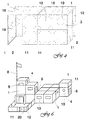
- a basic module according to one embodiment of the invention is erected partly of modular board like square basic element 1, 12 and, at suitable locations, alternatively of rectangular basic elements 11, respectively, and partly of elements comprising special details 4 or detail portions 2, 3 essentially obtained by omitting certain elements.
- At least some of the board like elements 1, 11, 12, 13 are structurally load bearing elements taking, in themselves, up those loads which might be caused by the dead weight of the structure and by the use for playing purposes.
- said special details comprise an opening 2 adjacent to the ground, said opening being intended for use as a door into the basic module, as well as an opening 3 adjacent to the ceiling and/or wall surface of said basic module and being intended for use as a window during playing, an alternative window being constituted by using a special element having a circular opening 4.
- Figure 2 discloses a number of elements 13 showing other examples of such details. Said details may comprise, for example, different kinds of closed openings 4, openings 5 open to one side, door elements 6, or e.g. a special text 7, a special coloring or other such special details promoting the fantasy education of children.
- the system may comprise e.g. special triangular gable elements (not especially shown in the Figures) or elements standing completely by themselves but being connectable to some element, for which a flag pole 8 in Figure 6 may be used as an example.
- Figures 4 to 6 disclose further examples of more complicated three dimensional room structures for use in play, where the structure according to Figure 5 simultaneously comprises normal functional solutions, in this case a portion 9 intended for use as a normal bed, at which the lower levels of the structure simultaneously may be used as steps.
- the structural kit may comprise, as a special detail, special ladder elements or elements having an integral ladder structure.
- the basic modules comprise at least one opening 2 intended for use as a door, but e.g. an embodiment structured for use as, for instance, a "pirate ship” may instead of a door comprise such basic modules which are accessible only from the top, and which represent “cargo holds", "prison dungeons” or the like spaces which may be utilized during playing.
- the structure of the three dimensional basic module is a cube having square modular sides.
- Said sides are primarily constituted of board like basic elements 1, 11, 12 based on a basic modular standard side measure "b" and manufactured from a suitable board material, e.g. plywood, sheet metal, plastic boards or the like.
- Said board like elements are as such dimensioned to take all such loads which a normal use of the structure may cause, and the structure can thus be erected without any further load bearing framework.
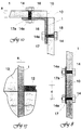
- each basic element has a defined board thickness "a" (see Figure 13).
- every modular side 10 has a modular width "b" of e.g. 30...120 centimeters, suitably 60, 80 or 100 centimeters, while said thickness "a" is of an order of 1 to 20 millimeters; for a material based on wood fibres it is suitably 4 to 12 millimeters; for outdoor use perhaps slightly more, e.g. 15 to 16 millimeters.
- said elements may comprise a load bearing connective edge (see for example 16' in Figure 12) surrounding boards made of a material which is essentially thinner, for instance of an order of 0.5 to 6 millimeters.
- said connecting edge 16' is suitably glued to said boards at at least one edge, while said edge in other cases may be more or less detachable in order to permit freer rebuilding possibilities.
- a smaller basic element for example one having a side width of 30 to 60 centimeters, in which case larger elements have sides of a width which is a multiple of the side width of said smaller element.
- Such smaller elements may also be interconnected at an angle, or alternatively they may have their edges directed one towards the other for constituting larger partial elements.
- Such smaller elements may also be used in combination with larger basic elements, as is evident from Figure 6 at the reference 20.
- Each basic element 1, 11, 12 is designed so that it may be connected to another corresponding element.
- each respective basic element i.e. at least said larger rectangular elements 1 and any possible additional elements 11, 12, comprises series of holes 18 (see Figure 3) into which interconnecting tightening elements, e.g. bolts 14 or the like, may be inserted in accordance with Figures 7 to 12.
- Corresponding holes are also arranged at at least one side edge or the like in elements 13 having said special details, and at any other possible extra elements 8.
- Said tightening elements 14 are used for the attachment of interconnecting elements 15, 16, 16' to said board like basic elements 1 and said extra elements 11, respectively, in which case said elements 14, 15, 16, 16' interact in order to connect selected board like elements either in a side-by-side relationship (see Figures 7, 8) or edge-to-edge at an angle (see figures 9 to 12). Since said element boards normally, as such, carry any such loads which the use might cause, the main function of said connecting elements 14, 15, 16, 16' will only be to interconnect the different board like elements 1, 11, 12, 13 into a desired three dimensional form. In certain especially heavily loaded cases said interconnecting elements, or special reinforcing elements may be used as enforcement especially against buckling.
- said bolts 14 or the like, as well as any related locking elements like nuts 14a or the like may be tightened using the same tool, for example a hexagon spanner, but also conventional screw heads 14' intended for a screw driver, or socket head caps or the like may be acceptable.
- said nut element 14a or the like may be replaced by a screw threading 14b made directly into the respective interconnecting elements 15, 16, 16', or alternatively in the actual board material or in a special reinforcing edging suitably made of metal or a plastic material.
- each respective element 15, 16, 16' comprises at least two holes 17, 17a, suitably one at each respective end of a respective interconnecting element 15, 16, 16'.
- interconnecting elements of a straight design have been generally referred to as 15, while the reference 16, 16' generally indicates elements for connecting at an angle.
- Figure 7 shows a connection using interconnecting elements having a short dimensional size in the lateral direction.
- the corresponding elements are in the form of an oblong rim, for example V-bars and/or flat iron, but said interconnecting elements 15 may of course also be of an oblong design, while said angle elements 16 may comprise for example console-like shorter elements.
- Figure 11 shows a connection where an interconnecting element 16 at at least one side has a leg 21 inserted into a groove in a corresponding board like element 1, and said Figure also shows an alternative interconnecting arrangement comprising a counter-sunk screw 14' and threading arranged in the angle bar 16 itself.
- Figure 12 shows an interconnection using rims having a special design with grooves 22 for receiving the edges 10 of said element boards 1, 11, 12, 13. For thicker board material said grooves are made correspondingly wider, and in certain cases one side of said groove may be completely removed so that said rim, in practice, actually corresponds to the angle bars discussed above.
- the arrangement mentioned above also facilitates the connection of boards of different thickness to the same rim.
- one or several interconnecting rims 16, 16' may comprise further grooves, in addition to said actual grooves 22 intended for receiving the primary element boards 1, 11, 12, 13. Said further grooves may be essentially parallel with said actual grooves 22, so that further boards, for example signboards or the like arranged in a parallel manner, may be attached to the same rim. Said rims 16, 16'may also comprise further grooves extending in a different direction, so that also boards which are not parallel with said primary element boards, for example inclined roofing boards or the like additional elements, may be attached in a simple manner to the same rim 16, 16'.
- each attachment point (and respective combination of said holes 17, 18) arranged in double so that the tightening element 14 for said attachment point may be inserted into an alternative of two hole series or the like fastening positions arranged generally close to another.
- This will prevent said tightening elements 14 especially in an inner corner from being positioned one against the other, which in certain cases (e.g. when using bolts having nuts arranged in the inner portions of said corner) would lead to problems due to the lack of space.
- This arrangement is more closely disclosed in Figure 12, where the respective X and Y axes of said tightening elements do not cross, since the hole 17' having the axis Y' is out of use.
- the elements 16, 16'acting as angle bars are constituted of rims having a generally essentially proper rectangular cross section, and in this case mutually displaced double holes 17, 17', 18 are indispensable, since only one respective bolt 14 or the like can be inserted in holes crossing each other in a common plane.
- the interconnection is usually (except for the embodiment disclosed in Figure 12) performed edge-to-edge, either at right angle one to another (see Figures 9 to 12) or in a common plane (see Figures 7, 8). In this manner one can erect spatial structures of a nearly arbitrary design. Since the interconnection of the elements is extremely simple also small children, perhaps with some initial aid from an older person, can manage to build his or her own playing environments from said basic and additional elements 1, 11, 12 and utilizing elements 13 comprising special details 4, 5, 6, 7, and these environments may easily be altered and extended at a later stage.
- two short interconnecting elements 15 are normally used (see Figure 7) or alternatively one longer element 16, 16' (see Figures 9, 12) extending over several holes 18 may be used.
- the number of interconnecting elements may be higher than two.
- said interconnecting elements 15, 16, 16' are provided with respective tightening elements 14.
- said interconnection may be performed totally without any particular interconnecting elements so that a board like element 1 is tightened in between two other elements, for example an element 12 and special elements 13 in accordance with Figure 13.
- said interconnecting elements 15, 16, 16' are pre-attached in a more or less permanent manner to at least one side 10 of an element.
- each proper board element 1, 11, 12, 13 at at least one edge suitably at several edges comprises holes 18 as discussed above, said holes preferably being arranged in a manner which is especially evident from Figure 3.
- the distance between said holes is selected so that to each proper board element 1, 11, 12, 13 an identical element is attachable, or an element one side of which has a modular size corresponding to, for instance, half said modular measure "b" of a proper board element 1, or to a multiple thereof.
- said holes 18 are suitably arranged at the outer edge 10 of each board element 1, 11, 12, 13, respectively, favorably at a mutually equal distance.
- At least the larger elements suitably comprise more centrally located holes 19 arranged at corresponding mutual distances from each other and from said holes 18 located at the edge, in which case said holes 19 in at least one direction are located in the inner portion of the surface area of the respective board element 1, 11.
- said board elements can be so attached that certain elements extend transversely from the centre of another element, as is evident from Figure 9.
- the exact position of said holes 18 in accordance with a favorable embodiment of the invention is more closely discussed in the appended claims.
- the disclosed embodiments comprise, besides quadratic basic elements 1 of a certain modular size, also elements of other forms and/or dimensions.
- the system may also be based on smaller elements 20, the side width of which correspond to half the side width of the larger elements discussed above.
- the system may further comprise other elements 11 of a rectangular form, or other quadratic elements 12 of another dimension than that of said basic elements.
- additional elements are characterized in that they comprise at least one side the dimensions of which correspond to a multiple of half the modular standard width of said rectangular basic elements, in which case said side suitably is provided with said holes 18 arranged in accordance with the principles discussed above.
Landscapes
- Toys (AREA)
- Conveying And Assembling Of Building Elements In Situ (AREA)
- Adornments (AREA)
- Tents Or Canopies (AREA)
- Glass Compositions (AREA)
- Joining Of Building Structures In Genera (AREA)
Claims (10)
- Elemente eines Baukastens, mittels dessen in einer spielerischen Art und Weise dreidimensionale Bauten nach Art eines Spielhauses aufbaubar sind, die brettartige Grundelemente (1, 11, 12), die aus im wesentlichen dreidimensionalem Brettmaterial aufgebaut sind, eine rechteckige Form besitzen und deren Maße auf einer modularen Seitengröße (b) basieren, verbindende Elementen (15, 16, 16'), die Teile aus einem haltbaren, mit Löchern versehenen Material umfassen, sowie in diese Löcher passende Befestigungselemente (14, 14') umfassen, wobei die brettartigen Grundelemente (1, 11, 12) und alle möglichen zusätzlichen Elemente (13, 20) für die Befestigungselemente (14, 14') passende Löcher (18, 19) aufweisen zum Verbinden mit den verbindenden Elemente (15, 16, 16') und zum Verbinden der Grundelemente (1, 11, 12) mit allen möglichen zusätzlichen Elementen (13, 20), um eine dreidimensionale Gebäudestruktur zu errichten, wobei die Maße der Elemente und der zusätzlichen Elemente (1, 11, 12, 13, 20) an wenigstens einer der Seiten einem Mehrfachen der modularen Größe (b) entsprechen und die Löcher (18, 19) für die verbindenden Elemente (14, 14') in dem jeweiligen Element in einer entsprechenden modularen Art und den entsprechenden Löchern (18, 19) eines anderen Elements gegenüberliegend so angeordnet sind, daß die Löcher (18, 19), innerhalb einer vernünftigen Toleranz, sich in einer solchen Entfernung (c) von einem ersten benachbarten äußeren Rand (10) des Elements befinden, daß die Entfernung die Hälfte des Abstandes zwischen entsprechenden Löchern im entsprechenden verbindenden Element (15, 16, 16') beträgt,
dadurch gekennzeichnet, daß
die äußersten entsprechenden Löcher (18) für die verbindenden Elemente (15, 16, 16') in einer Entfernung (d) von einem zweiten benachbarten äußeren Rand (10), der an den ersten äußeren Rand grenzt, angeordnet sind, die um die Breite (e) des entsprechenden verbindenden Elements (15, 16, 16') größer als die Hälfte der Entfernung zwischen entsprechenden Löchern in dem entsprechenden verbindenden Element (15, 16, 16') ist. - Elemente nach Anspruch 1, dadurch gekennzeichnet, daß in den Elementen (1, 11, 12, 13, 20) zusätzlich zu den Löchern (18) für die verbindenden Elemente (15, 16, 16') weitere Löcher (19) für die verbindenden Elemente (15, 16, 16') vorhanden sind, wobei die Löcher (19) sich in einem beträchtlich größerem Abstand von wenigstens einem der Ränder (10) des Elements befinden, aber in der gleichen gegenseitigen modularen internen Entfernung (f).
- Elemente nach Anspruch 1 oder 2, dadurch gekennzeichnet, daß in den Elementen (1, 11, 12, 13) mindestens ein Rand (10) verstärkende Mittel umfaßt, die zweckmäßig gleichzeitig als verbindende Elemente zur Verbindung zu einem oder mehreren benachbarten Elementen (1, 11, 12, 3, 20) dienen.
- Elemente nach Anspruch 3, dadurch gekennzeichnet, daß die verstärkenden Mittel äußere Kanten (16') umfassen, die sich an den äußeren Rändern der Elemente (1, 11, 12, 13, 20) befinden, vorzugsweise einen flachen und/oder eckigen Querschnitt aufweisen und zweckmäßig aus Metall, hartem Kunststoff, Holz oder dergleichen gemacht sind.
- Elemente nach Anspruch 3, dadurch gekennzeichnet, daß die verstärkenden Mittel Teile (21) die in einen jeweiligem Rand (10) der Elemente eingelassen sind und zweckmäßig an den Löchern (18) Teile mit Gewinde (14b) oder dergleichen für das jeweilige Befestigungselement (14) umfassen.
- Elemente nach einem der Ansprüche 1 bis 5, dadurch gekennzeichnet, daß die Elemente (1, 11, 112, 13, 20) so dimensioniert sind, daß sie Lasten, die durch den normalen Einsatz einer zusammengesetzten Gebäudestruktur auf das Element (1, 11, 12, 13) bei Gebrauch als Spielhaus oder dergleichen einwirken, in einer freitragenden Art aushalten.
- Elemente nach einem der Ansprüche 1 bis 6, dadurch gekennzeichnet, daß die Elemente (1, 11, 12, 13, 20) Einzelheiten und/oder Elemente umfassen, die das Spielen und/oder die phantasiefördernde Erziehung von Kindern unterstützen.
- Elemente nach Anspruch 7, dadurch gekennzeichnet, daß die Einzelheiten Öffnungen (4, 5, 6) umfassen, die Öffnungen (2, 3), die in lebensgroßen Gebäuden vorkommen, darstellen sollen.
- Elemente nach Anspruch 7, dadurch gekennzeichnet, daß die Einzelheiten Farben und/oder speziell angeordnete Markierungen (7) sind, die Funktionen, die in der Gesellschaft vorkommen, darstellen sollen.
- Elemente nach Anspruch 7, dadurch gekennzeichnet, daß die Einzelheiten zusätzliche strukturelle Merkmale, wie Türpaneele, Dachluken, Leitern, Fahnenmasten (8) und dergleichen sind.
Applications Claiming Priority (3)
| Application Number | Priority Date | Filing Date | Title |
|---|---|---|---|
| FI934489 | 1993-10-11 | ||
| FI934489A FI101348B1 (fi) | 1993-10-11 | 1993-10-11 | Rakennussarja ja sen elementit |
| PCT/FI1994/000457 WO1995010341A1 (en) | 1993-10-11 | 1994-10-11 | Construction kit and its elements |
Publications (2)
| Publication Number | Publication Date |
|---|---|
| EP0726799A1 EP0726799A1 (de) | 1996-08-21 |
| EP0726799B1 true EP0726799B1 (de) | 1999-09-01 |
Family
ID=8538752
Family Applications (1)
| Application Number | Title | Priority Date | Filing Date |
|---|---|---|---|
| EP94928909A Expired - Lifetime EP0726799B1 (de) | 1993-10-11 | 1994-10-11 | Konstruktionsbausatz sowie seine elemente |
Country Status (7)
| Country | Link |
|---|---|
| EP (1) | EP0726799B1 (de) |
| AT (1) | ATE183936T1 (de) |
| AU (1) | AU7814894A (de) |
| DE (1) | DE69420422T2 (de) |
| DK (1) | DK0726799T3 (de) |
| FI (1) | FI101348B1 (de) |
| WO (1) | WO1995010341A1 (de) |
Family Cites Families (3)
| Publication number | Priority date | Publication date | Assignee | Title |
|---|---|---|---|---|
| DE2119582A1 (de) * | 1971-04-22 | 1972-11-02 | Dentzer, Heinz, 7157 Murrhardt | Bausatz zu Spielzwecken |
| GB1378803A (en) * | 1973-05-04 | 1974-12-27 | Rodriguez J | Method of forming structures |
| GB2195907A (en) * | 1986-10-08 | 1988-04-20 | Marguerite Fiona Parsons | Constructional toy |
-
1993
- 1993-10-11 FI FI934489A patent/FI101348B1/fi not_active IP Right Cessation
-
1994
- 1994-10-11 AT AT94928909T patent/ATE183936T1/de not_active IP Right Cessation
- 1994-10-11 WO PCT/FI1994/000457 patent/WO1995010341A1/en not_active Ceased
- 1994-10-11 EP EP94928909A patent/EP0726799B1/de not_active Expired - Lifetime
- 1994-10-11 DK DK94928909T patent/DK0726799T3/da active
- 1994-10-11 AU AU78148/94A patent/AU7814894A/en not_active Abandoned
- 1994-10-11 DE DE69420422T patent/DE69420422T2/de not_active Expired - Fee Related
Also Published As
| Publication number | Publication date |
|---|---|
| DE69420422D1 (de) | 1999-10-07 |
| AU7814894A (en) | 1995-05-04 |
| DE69420422T2 (de) | 2000-03-30 |
| FI101348B (sv) | 1998-06-15 |
| FI934489A0 (fi) | 1993-10-11 |
| ATE183936T1 (de) | 1999-09-15 |
| FI101348B1 (fi) | 1998-06-15 |
| EP0726799A1 (de) | 1996-08-21 |
| WO1995010341A1 (en) | 1995-04-20 |
| DK0726799T3 (da) | 2000-03-27 |
| FI934489L (fi) | 1995-04-12 |
Similar Documents
| Publication | Publication Date | Title |
|---|---|---|
| US5681201A (en) | Toy building system | |
| CA2016934C (en) | Polygon-shaped house | |
| US4334868A (en) | Constructional kits | |
| US4372076A (en) | Modular interlocking block construction toy | |
| CA2255184C (en) | Knockdown garden deck | |
| US5007220A (en) | Non-periodic and periodic layered space frames having prismatic nodes | |
| US5575120A (en) | Design and construction module | |
| US6173538B1 (en) | Modular construction system | |
| US5174078A (en) | Roof construction for playhouse | |
| US5725411A (en) | Construction beam block toy with selective angular interlock | |
| US6059630A (en) | Log based assembly set | |
| US4665665A (en) | Building structure | |
| EP0726799B1 (de) | Konstruktionsbausatz sowie seine elemente | |
| US5390452A (en) | Modular building block | |
| US5492307A (en) | Modular fence apparatus | |
| US4569665A (en) | Play building element | |
| RU2070083C1 (ru) | Игровой конструктор | |
| KR101430558B1 (ko) | 다용도 조립식 구조물 | |
| US20050148436A1 (en) | Climbing playsets | |
| GB2153873A (en) | Building systems comprising interlocking components | |
| GB1571153A (en) | Building elements for children's play houses | |
| JPH0127799Y2 (de) | ||
| JP2002242304A (ja) | 木造構造物の骨組構造およびその組立方法 | |
| RU190588U1 (ru) | Панель с универсальным соединением | |
| RU229U1 (ru) | Детский строительный конструктор |
Legal Events
| Date | Code | Title | Description |
|---|---|---|---|
| PUAI | Public reference made under article 153(3) epc to a published international application that has entered the european phase |
Free format text: ORIGINAL CODE: 0009012 |
|
| 17P | Request for examination filed |
Effective date: 19960507 |
|
| AK | Designated contracting states |
Kind code of ref document: A1 Designated state(s): AT BE DE DK FR GB IE IT NL SE |
|
| 17Q | First examination report despatched |
Effective date: 19980327 |
|
| GRAG | Despatch of communication of intention to grant |
Free format text: ORIGINAL CODE: EPIDOS AGRA |
|
| GRAG | Despatch of communication of intention to grant |
Free format text: ORIGINAL CODE: EPIDOS AGRA |
|
| GRAH | Despatch of communication of intention to grant a patent |
Free format text: ORIGINAL CODE: EPIDOS IGRA |
|
| GRAH | Despatch of communication of intention to grant a patent |
Free format text: ORIGINAL CODE: EPIDOS IGRA |
|
| GRAA | (expected) grant |
Free format text: ORIGINAL CODE: 0009210 |
|
| AK | Designated contracting states |
Kind code of ref document: B1 Designated state(s): AT BE DE DK FR GB IE IT NL SE |
|
| PG25 | Lapsed in a contracting state [announced via postgrant information from national office to epo] |
Ref country code: IT Free format text: LAPSE BECAUSE OF FAILURE TO SUBMIT A TRANSLATION OF THE DESCRIPTION OR TO PAY THE FEE WITHIN THE PRESCRIBED TIME-LIMIT;WARNING: LAPSES OF ITALIAN PATENTS WITH EFFECTIVE DATE BEFORE 2007 MAY HAVE OCCURRED AT ANY TIME BEFORE 2007. THE CORRECT EFFECTIVE DATE MAY BE DIFFERENT FROM THE ONE RECORDED. Effective date: 19990901 Ref country code: FR Free format text: LAPSE BECAUSE OF FAILURE TO SUBMIT A TRANSLATION OF THE DESCRIPTION OR TO PAY THE FEE WITHIN THE PRESCRIBED TIME-LIMIT Effective date: 19990901 Ref country code: BE Free format text: LAPSE BECAUSE OF FAILURE TO SUBMIT A TRANSLATION OF THE DESCRIPTION OR TO PAY THE FEE WITHIN THE PRESCRIBED TIME-LIMIT Effective date: 19990901 Ref country code: AT Free format text: LAPSE BECAUSE OF FAILURE TO SUBMIT A TRANSLATION OF THE DESCRIPTION OR TO PAY THE FEE WITHIN THE PRESCRIBED TIME-LIMIT Effective date: 19990901 |
|
| REF | Corresponds to: |
Ref document number: 183936 Country of ref document: AT Date of ref document: 19990915 Kind code of ref document: T |
|
| REF | Corresponds to: |
Ref document number: 69420422 Country of ref document: DE Date of ref document: 19991007 |
|
| PG25 | Lapsed in a contracting state [announced via postgrant information from national office to epo] |
Ref country code: IE Free format text: LAPSE BECAUSE OF NON-PAYMENT OF DUE FEES Effective date: 19991101 |
|
| REG | Reference to a national code |
Ref country code: IE Ref legal event code: FG4D |
|
| EN | Fr: translation not filed | ||
| REG | Reference to a national code |
Ref country code: DK Ref legal event code: T3 |
|
| PLBE | No opposition filed within time limit |
Free format text: ORIGINAL CODE: 0009261 |
|
| STAA | Information on the status of an ep patent application or granted ep patent |
Free format text: STATUS: NO OPPOSITION FILED WITHIN TIME LIMIT |
|
| 26N | No opposition filed | ||
| REG | Reference to a national code |
Ref country code: IE Ref legal event code: MM4A |
|
| REG | Reference to a national code |
Ref country code: GB Ref legal event code: IF02 |
|
| PGFP | Annual fee paid to national office [announced via postgrant information from national office to epo] |
Ref country code: GB Payment date: 20030919 Year of fee payment: 10 |
|
| PGFP | Annual fee paid to national office [announced via postgrant information from national office to epo] |
Ref country code: SE Payment date: 20031020 Year of fee payment: 10 |
|
| PGFP | Annual fee paid to national office [announced via postgrant information from national office to epo] |
Ref country code: NL Payment date: 20031022 Year of fee payment: 10 |
|
| PGFP | Annual fee paid to national office [announced via postgrant information from national office to epo] |
Ref country code: DK Payment date: 20031027 Year of fee payment: 10 |
|
| PGFP | Annual fee paid to national office [announced via postgrant information from national office to epo] |
Ref country code: DE Payment date: 20031028 Year of fee payment: 10 |
|
| PG25 | Lapsed in a contracting state [announced via postgrant information from national office to epo] |
Ref country code: GB Free format text: LAPSE BECAUSE OF NON-PAYMENT OF DUE FEES Effective date: 20041011 |
|
| PG25 | Lapsed in a contracting state [announced via postgrant information from national office to epo] |
Ref country code: SE Free format text: LAPSE BECAUSE OF NON-PAYMENT OF DUE FEES Effective date: 20041012 |
|
| PG25 | Lapsed in a contracting state [announced via postgrant information from national office to epo] |
Ref country code: DK Free format text: LAPSE BECAUSE OF NON-PAYMENT OF DUE FEES Effective date: 20041101 |
|
| PG25 | Lapsed in a contracting state [announced via postgrant information from national office to epo] |
Ref country code: NL Free format text: LAPSE BECAUSE OF NON-PAYMENT OF DUE FEES Effective date: 20050501 |
|
| PG25 | Lapsed in a contracting state [announced via postgrant information from national office to epo] |
Ref country code: DE Free format text: LAPSE BECAUSE OF NON-PAYMENT OF DUE FEES Effective date: 20050503 |
|
| EUG | Se: european patent has lapsed | ||
| GBPC | Gb: european patent ceased through non-payment of renewal fee |
Effective date: 20041011 |
|
| REG | Reference to a national code |
Ref country code: DK Ref legal event code: EBP |
|
| NLV4 | Nl: lapsed or anulled due to non-payment of the annual fee |
Effective date: 20050501 |