EP0726849B1 - Rakelklemmanordnung für eine druckmaschine - Google Patents
Rakelklemmanordnung für eine druckmaschine Download PDFInfo
- Publication number
- EP0726849B1 EP0726849B1 EP95926851A EP95926851A EP0726849B1 EP 0726849 B1 EP0726849 B1 EP 0726849B1 EP 95926851 A EP95926851 A EP 95926851A EP 95926851 A EP95926851 A EP 95926851A EP 0726849 B1 EP0726849 B1 EP 0726849B1
- Authority
- EP
- European Patent Office
- Prior art keywords
- doctor blade
- bladder
- chamber body
- leaf spring
- clamping assembly
- Prior art date
- Legal status (The legal status is an assumption and is not a legal conclusion. Google has not performed a legal analysis and makes no representation as to the accuracy of the status listed.)
- Expired - Lifetime
Links
- 125000006850 spacer group Chemical group 0.000 claims abstract description 10
- 238000007774 anilox coating Methods 0.000 description 15
- 238000004140 cleaning Methods 0.000 description 2
- 230000005012 migration Effects 0.000 description 2
- 238000013508 migration Methods 0.000 description 2
- 238000005507 spraying Methods 0.000 description 2
- 230000002950 deficient Effects 0.000 description 1
- 230000001419 dependent effect Effects 0.000 description 1
- 238000012986 modification Methods 0.000 description 1
- 230000004048 modification Effects 0.000 description 1
Images

Classifications
-
- B—PERFORMING OPERATIONS; TRANSPORTING
- B41—PRINTING; LINING MACHINES; TYPEWRITERS; STAMPS
- B41F—PRINTING MACHINES OR PRESSES
- B41F31/00—Inking arrangements or devices
- B41F31/02—Ducts, containers, supply or metering devices
- B41F31/027—Ink rail devices for inking ink rollers
-
- B—PERFORMING OPERATIONS; TRANSPORTING
- B41—PRINTING; LINING MACHINES; TYPEWRITERS; STAMPS
- B41F—PRINTING MACHINES OR PRESSES
- B41F9/00—Rotary intaglio printing presses
- B41F9/06—Details
- B41F9/08—Wiping mechanisms
- B41F9/10—Doctors, scrapers, or like devices
- B41F9/109—Doctors, scrapers, or like devices exchanging doctor blades
Definitions
- the present invention relates generally to printing machines, and more particularly, is directed to the clamping of a doctor blade relative to an anilox roll.
- an ink transfer or anilox roll transfers ink to an adjacent plate roll for printing.
- Ink is supplied to the anilox roll from an ink chamber defined by a chamber body which partially surrounds the anilox roll. Specifically, ink is supplied through an ink supply tube and then through an ink supply line in the chamber body, into the ink chamber. In like manner, ink is removed from the ink chamber through an ink return line in the chamber body and then through an ink return tube.
- doctor blades are provided at the entry and exit positions of the anilox roll relative to the ink chamber.
- the doctor blades are fixed to the chamber body by bolts so that the doctor blades overhang the chamber body and contact the anilox roll.
- EP-A-0 611 649 which forms prior art pursuant to Article 54 (3) EPC discloses a doctor blade clamping assembly according to the preamble of claim 1.
- spring means for applying a biasing force to the doctor blade so as to clamp the same to the chamber body are formed by a lever pivotally mounted to the chamber body and having a first arm which extends around a side portion of the chamber body and is biased to engage the doctor blade on the front side of the chamber body.
- Biasing means for biasing the lever in a direction to release the doctor blade from the first arm are formed by a cylinder which is mounted on the rear side of the chamber body and acts upon a rearwardly projecting second arm of the lever.
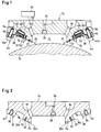
- an ink transfer or anilox roll 10 transfers ink to an adjacent plate roll (not shown) for printing.
- Ink is supplied to anilox roll 10 from an ink chamber 12 defined by a chamber body 14 which partially surrounds anilox roll 10. Specifically, ink is supplied to ink chamber 12 through an ink supply line 16 in chamber body 14, and ink is removed from ink chamber 12 through an ink return line 18 in chamber body 14.
- anilox roll 10 passes through ink chamber 12 and picks up ink for printing.
- the ink is metered by means of doctor blades 20 held to the inlet and outlet ends of chamber body 14, with the free ends of doctor blades 20 being in contact with the outer surface of anilox roll 10.
- O-ring seals 22 are provided in recesses 24 of chamber body 14, in contact with doctor blades 20, to prevent migration of ink.
- chamber body 14 includes a cleaning solution supply line 26 having spraying means 28 for spraying a cleaning solution into ink chamber 12, in order to clean ink chamber 12 and anilox roll 10.
- chamber body 14 includes inclined surfaces 30 and 32 at the inlet and outlet ends thereof that converge in directions toward each other, and which terminate at inner edges 30a and 32a thereof corresponding to the outer boundaries of ink chamber 12.
- Each inclined surface 30 and 32 is comprised of an outer inclined portion 31 and an inner inclined portion 33, with inner inclined portion 33 having a slightly steeper slope than outer inclined portion 31.
- the recesses 24 are provided in inner inclined portions 33, at positions spaced immediately outwardly of inner edges 30a and 32a. Further, a plurality of threaded bolt holes 34 are provided in outer inclined portions 31 of each inclined surface 30 and 32. In addition, large recessed areas 36 are also provided in outer inclined portions 31, at positions between the respective smaller recesses 24 and threaded bolt holes 34.
- a doctor blade 20 is positioned against inner inclined portion 33 of each inclined surface 30 and 32, such that the rear edges of doctor blades 20 extend outwardly or rearwardly almost to the junction of inner and outer inclined portions 31 and 33, and such that the front edges of doctor blades 20 are in contact with anilox roll 10.
- O-ring seals 22 prevent migration of ink between doctor blades 20 and the front and rear inclined surfaces 30 and 32.
- each leaf spring 38 is secured to each inclined surface 30 and 32 so as to partially overlie doctor blades 20, and thereby apply a biasing force to doctor blades 20 to retain the same in position.
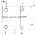
- each leaf spring 38 is preferably comprised of a primary leaf 40 which overlies the respective doctor blade 20 and a secondary leaf 42 which overlies first leaf 40, but which does not overlie the respective doctor blade 20.
- Each primary leaf 40 has a length substantially equal to the length of each inclined surface 30 and 32, while each secondary leaf 42 has a length that extends inwardly to a position just past the inner edge 36a of the respective large recessed area 36.
- secondary leaf 42 may be eliminated, or still further, more than two leaves may be provided for each leaf spring 38.
- leaf spring 38 has been shown and described, any other biasing means can be used in place thereof, such as a coil spring, inflatable bladder or the like.
- Bolts 44 extend through holes 41 at rear portions of leaves 40 and 42 of each leaf spring 38, and are threadedly received in threaded bolt holes 34.
- a spacer washer 46 is preferably positioned between the enlarged head 44a of each bolt 44 and the respective leaf spring 38 so that the turning forces of enlarged heads 44a are not transferred to leaf springs 38.
- leaf springs 38 apply a large pressure on doctor blades 20, for example, on the order of 525 kPa (80 psi), thereby fixing doctor blades 20 at their respective positions.
- an inflatable bladder 48 is positioned in each large recessed area 36, along with a spacer 50.
- Spacer 50 is interposed between and in contact with inflatable bladder 48 and the primary leaf 40 of each leaf spring 38.
- bladder In the normal operating position, bladder is deflated, as shown by the solid lines in Figs. 1 and 3, whereby primary leaf 40 is pressed against inclined surfaces 30 and 32 and presses down on doctor blade 20 to hold the same in position.
- a conduit 52 extends from the rear face of chamber body 14 to the large recessed area 36, and is connected with bladder 48 thereat.
- a bladder control 54 is connected with conduit 52 to control inflation and deflation of bladder 48.
- bladder control 54 supplies pressurized air or other gas to the bladder 48 to inflate the same, and provides a suction to remove the pressurized air or other gas from the bladder 48.
- only one conduit 54 is shown for both bladders 48 on the entry and exit sides of chamber body 14. In this regard, the connection between the bladders 48 on both sides of chamber body 14 is not shown. However, separate conduits 52 may be provided for each bladder 48.
- a stop 56 is secured to chamber body 14. Specifically, stop 56 is formed by the enlarged heads 58a of bolts 58, with the shafts 58b of bolts 58 extending through respective holes 60 formed only in primary leaf 40 and being threadedly engaged within threaded bolt holes 62 formed in inner inclined portion 33 of inclined surfaces 30 and 32. As shown, each bolt head 58a is spaced from inner inclined portion 33 so that leaf spring 38 abuts thereagainst when biased by bladder 48 and spacer 50. In this manner, the extent that a leaf spring 38 can be biased away from an inclined surface 30 or 32 can be varied by adjusting bolts 58.
- spacer 50 can be eliminated so that bladder 48 directly contacts leaf spring 38.
Landscapes
- Engineering & Computer Science (AREA)
- Mechanical Engineering (AREA)
- Inking, Control Or Cleaning Of Printing Machines (AREA)
- Screen Printers (AREA)
- Rotary Presses (AREA)
- Manufacturing Of Printed Wiring (AREA)
- Jigs For Machine Tools (AREA)
- Press Drives And Press Lines (AREA)
Claims (8)
- Rakelklemmanordnung in einer Druckmaschine mit einem Kammerkörper (14), der angrenzend an eine Walze (10) positioniert ist, wobei die Klemmordnung aufweist:eine Federeinrichtung (38) zum Ausüben einer Vorspannkraft auf ein Rakelmesser (20), damit das Rakelmesser am Kammerkörper geklemmt wird,eine Befestigungseinrichtung (44) zur Befestigung der Federeinrichtung an dem Kammerkörper in einer wenigstens teilweise überlagernden Beziehung zu dem Rakelmesser, so daß die Federeinrichtung die Vorspannkraft auf das Rakelmesser ausübt, um das Rakelmesser am Kammerkörper zu klemmen, undeiner Spanneinrichtung (48) zum Spannen der Federeinrichtung in einer Richtung von dem Rakelmesser weg, um das Rakelmesser von der Vorspannkraft zu entlasten,
wobei der Kammerkörper (14) einen ausgenommenen Bereich (36) aufweist, der in einem an das Rakelmesser (20) angrenzenden Oberflächenabschnitt (31) ausgebildet ist, und die Spanneinrichtung eine aufblasbare Balgeinrichtung (48) aufweist, die in dem ausgenommenen Bereich (36) positioniert ist, um die Federeinrichtung (38) von dem Rakelmesser wegzudrücken, um das Rakelmesser von der Vorspannkraft der Federeinrichtung zu entlasten. - Rakelklemmanordnung nach Anspruch 1, bei der die Federeinrichtung (38) eine Blattfeder aufweist.
- Rakelklemmanordnung nach Anspruch 2, bei der die Blattfeder (38) mehrere Blätter (40, 42) aufweist, die einander überlagernd zusammengebaut sind und von denen wenigstens einige unterschiedliche Längen haben.
- Rakelklemmanordnung nach Anspruch 2 oder 3, bei der die Befestigungseinrichtung wenigstens einen Bolzen (44) aufweist, der sich teilweise durch die Blattfeder (38) erstreckt und am Kammerkörper (14) befestigt ist.
- Rakelklemmanordnung nach einem der vorstehenden Ansprüche, bei der die Spanneinrichtung aufweist:eine Leitung (52), die sich durch den Kammerkörper erstreckt und mit der Balgeinrichtung (48) verbunden ist undeine Balg-Steuereinrichtung (54), die mit der Leitung verbunden ist, um das Aufblasen und Kollabieren der Balgeinrichtung über diese Leitung zu steuern.
- Rakelklemmanordnung nach einem der vorstehenden Ansprüche, bei der die Spanneinrichtung weiterhin einen Abstandshalter (50) aufweist, der in dem ausgenommenen Bereich (36) zwischen der Balgeinrichtung (48) und der Federeinrichtung (38) angeordnet ist.
- Rakelklemmanordnung nach einem der vorstehenden Ansprüche, mit einer Anschlageinrichtung (56) zur Begrenzung der Bewegung der Federeinrichtung (38) in einer Richtung von dem Rakelmesser (20) weg.
- Rakelklemmanordnung nach Anspruch 7, bei der die Anschlageinrichtung einen Bolzen (58) aufweist, der sich teilweise durch die Federeinrichtung (38) erstreckt und am Kammerkörper (14) befestigt ist.
Applications Claiming Priority (3)
| Application Number | Priority Date | Filing Date | Title |
|---|---|---|---|
| US282261 | 1988-12-09 | ||
| US08/282,261 US5517918A (en) | 1994-07-29 | 1994-07-29 | Doctor blade clamping assembly for a printing press |
| PCT/EP1995/002688 WO1996004140A1 (en) | 1994-07-29 | 1995-07-11 | Doctor blade clamping assembly for a printing press |
Publications (2)
| Publication Number | Publication Date |
|---|---|
| EP0726849A1 EP0726849A1 (de) | 1996-08-21 |
| EP0726849B1 true EP0726849B1 (de) | 1999-02-03 |
Family
ID=23080725
Family Applications (1)
| Application Number | Title | Priority Date | Filing Date |
|---|---|---|---|
| EP95926851A Expired - Lifetime EP0726849B1 (de) | 1994-07-29 | 1995-07-11 | Rakelklemmanordnung für eine druckmaschine |
Country Status (8)
| Country | Link |
|---|---|
| US (1) | US5517918A (de) |
| EP (1) | EP0726849B1 (de) |
| JP (1) | JP3490091B2 (de) |
| AT (1) | ATE176424T1 (de) |
| DE (1) | DE69507687T2 (de) |
| DK (1) | DK0726849T3 (de) |
| ES (1) | ES2128752T3 (de) |
| WO (1) | WO1996004140A1 (de) |
Families Citing this family (15)
| Publication number | Priority date | Publication date | Assignee | Title |
|---|---|---|---|---|
| WO1998018630A1 (de) * | 1996-10-25 | 1998-05-07 | Koenig & Bauer Ag | Farbkasten |
| WO1998028140A1 (de) * | 1996-12-21 | 1998-07-02 | Koenig & Bauer Ag | Verfahren und einrichtung zum einfärben einer walze |
| NL1006861C2 (nl) * | 1997-08-27 | 1999-03-02 | Cornelis Gorter | Kamerrakelsysteem. |
| US6119595A (en) * | 1997-10-06 | 2000-09-19 | R. J. Reynolds Tobacco Company | Gravure printing press with encapsulated ink applicator and method |
| ES2192179T3 (es) | 1999-06-22 | 2003-10-01 | Tresu Production As | Sistema de rasqueta. |
| DE10255411A1 (de) * | 2002-11-28 | 2004-06-24 | Windmöller & Hölscher Kg | Farbkammerrakel |
| CN101400518A (zh) * | 2006-03-09 | 2009-04-01 | 图像印刷与科技公司 | 用于高粘度墨的刮刀腔 |
| CN101758654B (zh) * | 2009-12-29 | 2014-12-03 | 汕头大学 | 凹版印刷机的刮墨装置及刮墨方法 |
| JP5701364B1 (ja) * | 2013-11-05 | 2015-04-15 | 三菱重工印刷紙工機械株式会社 | フレキソ印刷機のインキ洗浄装置及びインキ洗浄方法 |
| FR3068642A1 (fr) * | 2017-07-07 | 2019-01-11 | Bobst Lyon | Corps principal de chambre a racles, chambre a racles associee et procedes de fabrication associes. |
| CN108380541A (zh) * | 2018-04-24 | 2018-08-10 | 邢台海裕锂能电池设备有限公司 | 自适应气囊刮刀 |
| CN110154515A (zh) * | 2018-07-05 | 2019-08-23 | 上海鼎龙机械有限公司 | 印刷开槽模切机的刮刀快速拆换装置 |
| CN117529006A (zh) * | 2022-07-27 | 2024-02-06 | 莫列斯有限公司 | 连接器组件 |
| CN116834425A (zh) * | 2023-07-29 | 2023-10-03 | 上海宇泽机电设备有限公司 | 一种凹版涂布密闭刮刀 |
| CN118455154A (zh) * | 2024-06-18 | 2024-08-09 | 靖江市高新窑炉材料有限公司 | 一种双气囊刮刀摆动架 |
Family Cites Families (16)
| Publication number | Priority date | Publication date | Assignee | Title |
|---|---|---|---|---|
| AT215942B (de) * | 1958-04-29 | 1961-06-26 | Richard Kurt Smejda | Vorrichtung zur Anpassung und Einstellung des Vielfarbenzufuhrkastens gegen die Rouleauxdruckwalze |
| US3116688A (en) * | 1959-12-23 | 1964-01-07 | Koppers Co Inc | Ink fountain |
| US3122767A (en) * | 1962-07-23 | 1964-03-03 | Bird Machine Co | Sectional doctor blade holder |
| US3399420A (en) * | 1964-03-06 | 1968-09-03 | Beloit Corp | Doctor shape control device |
| US3593663A (en) * | 1969-06-03 | 1971-07-20 | Zerand Corp | Doctor blade assembly for printing equipment |
| DE2121753C3 (de) * | 1971-05-03 | 1979-10-11 | Albert-Frankenthal Ag, 6710 Frankenthal | Vorrichtung zum Festspannen des Rakelmessers im Rakelträger von Tiefdruck-Rotationsmaschinen |
| GB1507825A (en) * | 1974-04-08 | 1978-04-19 | Ahlen & Akerlunds Forlags Ab | Method and device for stripping excess ink from a rotating printing roll in rotogravure presses |
| US4241691A (en) * | 1978-08-30 | 1980-12-30 | Monsanto Company | Doctor blade holder |
| AT364589B (de) * | 1979-08-01 | 1981-10-27 | Haemmerle Ag | Spannvorrichtung zur befestigung eines werkzeuges an einem werkzeughalter |
| US4665859A (en) * | 1985-12-11 | 1987-05-19 | Thermo Electron-Web Systems, Inc. | Finger-type doctor blade holder |
| IT1210291B (it) * | 1987-05-15 | 1989-09-14 | Schiavi Cesare Costruz Meccan | Dispositivo di bloccaggio della lama raschia cilindro in unamacchina da stampa rotativa rotocalco |
| US4821672A (en) | 1987-06-22 | 1989-04-18 | Nick Bruno | Doctor blade assembly with rotary end seals and interchangeable heads |
| CH676694A5 (de) * | 1987-07-06 | 1991-02-28 | Juerg Holderegger | |
| DE3910497C1 (de) * | 1989-04-01 | 1990-09-13 | Man Roland Druckmaschinen Ag, 6050 Offenbach, De | |
| US5230775A (en) * | 1990-06-05 | 1993-07-27 | Thermo Electron Web Systems, Inc. | Blade edge loading control for doctoring apparatus |
| AU5306694A (en) * | 1993-01-15 | 1994-07-21 | Paper Converting Machine Company | Apparatus and method for doctor blade replacement in a flexographic press |
-
1994
- 1994-07-29 US US08/282,261 patent/US5517918A/en not_active Expired - Lifetime
-
1995
- 1995-07-11 EP EP95926851A patent/EP0726849B1/de not_active Expired - Lifetime
- 1995-07-11 AT AT95926851T patent/ATE176424T1/de active
- 1995-07-11 WO PCT/EP1995/002688 patent/WO1996004140A1/en not_active Ceased
- 1995-07-11 ES ES95926851T patent/ES2128752T3/es not_active Expired - Lifetime
- 1995-07-11 DE DE69507687T patent/DE69507687T2/de not_active Expired - Lifetime
- 1995-07-11 JP JP50611796A patent/JP3490091B2/ja not_active Expired - Fee Related
- 1995-07-11 DK DK95926851T patent/DK0726849T3/da active
Also Published As
| Publication number | Publication date |
|---|---|
| EP0726849A1 (de) | 1996-08-21 |
| DE69507687T2 (de) | 1999-08-05 |
| WO1996004140A1 (en) | 1996-02-15 |
| ATE176424T1 (de) | 1999-02-15 |
| DK0726849T3 (da) | 1999-09-20 |
| US5517918A (en) | 1996-05-21 |
| ES2128752T3 (es) | 1999-05-16 |
| DE69507687D1 (de) | 1999-03-18 |
| JPH09503175A (ja) | 1997-03-31 |
| JP3490091B2 (ja) | 2004-01-26 |
Similar Documents
| Publication | Publication Date | Title |
|---|---|---|
| US5517918A (en) | Doctor blade clamping assembly for a printing press | |
| US3828672A (en) | Apparatus for fitting flexible printing plates and rigging to printing press cylinders | |
| EP0499382B1 (de) | Rakelhalter und Druckmaschine mit diesem Halter | |
| US8087440B2 (en) | Embossing device | |
| US5515782A (en) | Cylinder cleaning apparatus for printing press | |
| EP0215645B1 (de) | Montieren von Matrizen und Druckplatten | |
| GB2248424A (en) | Printing and like apparatus having a roll with a doctor member | |
| US4718264A (en) | Lubrication of rolling mills | |
| US5345867A (en) | Doctor blade bar assembly | |
| US6119595A (en) | Gravure printing press with encapsulated ink applicator and method | |
| US4683822A (en) | Die mounting apparatus | |
| JPH11170151A5 (de) | ||
| EP0372253A3 (de) | Reinigungsvorrichtung für einen Druckmaschinengegendruckzylinder | |
| EP0681915A3 (de) | Vorrichtung zum Aufziehen flexibler Druckformen. | |
| EP0388757A1 (de) | Drückgerät in einem Apparat zum Reinigen des Gummituchzylinders einer Druckmaschine | |
| US5345866A (en) | Doctor blade bar assembly | |
| KR200223728Y1 (ko) | 에지밴딩기의 에지밴드 예열장치 | |
| JPS59111853A (ja) | 輪転印刷機用インク付着装置及びインク溜め | |
| EP0515534B1 (de) | Beschichtungskopf zum auftragen einer streichschicht auf eine papierbahn | |
| US4408531A (en) | Blanket tensioning system in press | |
| US5735211A (en) | Clamping and tensioning device for printing plates | |
| US4938131A (en) | Clamp device for the cylinder wiper blade in a rotogravure printing machine | |
| JP4965010B2 (ja) | 印刷機のインキ溜め用側壁 | |
| KR102675359B1 (ko) | 고정용 지그 | |
| ATE139723T1 (de) | Vorrichtung zum schleifen einer zylinderoberfläche, insbesondere einer walze einer papiermaschine |
Legal Events
| Date | Code | Title | Description |
|---|---|---|---|
| PUAI | Public reference made under article 153(3) epc to a published international application that has entered the european phase |
Free format text: ORIGINAL CODE: 0009012 |
|
| 17P | Request for examination filed |
Effective date: 19960207 |
|
| AK | Designated contracting states |
Kind code of ref document: A1 Designated state(s): AT BE CH DE DK ES FR GB IE IT LI LU NL SE |
|
| 17Q | First examination report despatched |
Effective date: 19961205 |
|
| GRAG | Despatch of communication of intention to grant |
Free format text: ORIGINAL CODE: EPIDOS AGRA |
|
| GRAG | Despatch of communication of intention to grant |
Free format text: ORIGINAL CODE: EPIDOS AGRA |
|
| GRAH | Despatch of communication of intention to grant a patent |
Free format text: ORIGINAL CODE: EPIDOS IGRA |
|
| GRAH | Despatch of communication of intention to grant a patent |
Free format text: ORIGINAL CODE: EPIDOS IGRA |
|
| GRAA | (expected) grant |
Free format text: ORIGINAL CODE: 0009210 |
|
| AK | Designated contracting states |
Kind code of ref document: B1 Designated state(s): AT BE CH DE DK ES FR GB IE IT LI LU NL SE |
|
| REF | Corresponds to: |
Ref document number: 176424 Country of ref document: AT Date of ref document: 19990215 Kind code of ref document: T |
|
| REG | Reference to a national code |
Ref country code: CH Ref legal event code: EP |
|
| REG | Reference to a national code |
Ref country code: IE Ref legal event code: FG4D |
|
| ET | Fr: translation filed | ||
| ITF | It: translation for a ep patent filed | ||
| REF | Corresponds to: |
Ref document number: 69507687 Country of ref document: DE Date of ref document: 19990318 |
|
| REG | Reference to a national code |
Ref country code: CH Ref legal event code: NV Representative=s name: PATENTANWAELTE SCHAAD, BALASS, MENZL & PARTNER AG |
|
| REG | Reference to a national code |
Ref country code: ES Ref legal event code: FG2A Ref document number: 2128752 Country of ref document: ES Kind code of ref document: T3 |
|
| REG | Reference to a national code |
Ref country code: DK Ref legal event code: T3 |
|
| PLBE | No opposition filed within time limit |
Free format text: ORIGINAL CODE: 0009261 |
|
| STAA | Information on the status of an ep patent application or granted ep patent |
Free format text: STATUS: NO OPPOSITION FILED WITHIN TIME LIMIT |
|
| 26N | No opposition filed | ||
| REG | Reference to a national code |
Ref country code: GB Ref legal event code: IF02 |
|
| PGFP | Annual fee paid to national office [announced via postgrant information from national office to epo] |
Ref country code: LU Payment date: 20080714 Year of fee payment: 14 |
|
| PG25 | Lapsed in a contracting state [announced via postgrant information from national office to epo] |
Ref country code: LU Free format text: LAPSE BECAUSE OF NON-PAYMENT OF DUE FEES Effective date: 20090711 |
|
| PGFP | Annual fee paid to national office [announced via postgrant information from national office to epo] |
Ref country code: DK Payment date: 20110712 Year of fee payment: 17 Ref country code: CH Payment date: 20110706 Year of fee payment: 17 |
|
| PGFP | Annual fee paid to national office [announced via postgrant information from national office to epo] |
Ref country code: IE Payment date: 20120710 Year of fee payment: 18 Ref country code: GB Payment date: 20120711 Year of fee payment: 18 Ref country code: SE Payment date: 20120711 Year of fee payment: 18 |
|
| PGFP | Annual fee paid to national office [announced via postgrant information from national office to epo] |
Ref country code: BE Payment date: 20120713 Year of fee payment: 18 Ref country code: ES Payment date: 20120824 Year of fee payment: 18 Ref country code: FR Payment date: 20120720 Year of fee payment: 18 Ref country code: DE Payment date: 20120704 Year of fee payment: 18 Ref country code: IT Payment date: 20120713 Year of fee payment: 18 |
|
| PGFP | Annual fee paid to national office [announced via postgrant information from national office to epo] |
Ref country code: NL Payment date: 20120710 Year of fee payment: 18 |
|
| PGFP | Annual fee paid to national office [announced via postgrant information from national office to epo] |
Ref country code: AT Payment date: 20120626 Year of fee payment: 18 |
|
| BERE | Be: lapsed |
Owner name: *FISCHER & KRECKE G.M.B.H. & CO. Effective date: 20130731 |
|
| REG | Reference to a national code |
Ref country code: NL Ref legal event code: V1 Effective date: 20140201 |
|
| REG | Reference to a national code |
Ref country code: DK Ref legal event code: EBP Effective date: 20130731 |
|
| REG | Reference to a national code |
Ref country code: CH Ref legal event code: PL |
|
| REG | Reference to a national code |
Ref country code: SE Ref legal event code: EUG |
|
| REG | Reference to a national code |
Ref country code: AT Ref legal event code: MM01 Ref document number: 176424 Country of ref document: AT Kind code of ref document: T Effective date: 20130711 |
|
| GBPC | Gb: european patent ceased through non-payment of renewal fee |
Effective date: 20130711 |
|
| REG | Reference to a national code |
Ref country code: IE Ref legal event code: MM4A |
|
| REG | Reference to a national code |
Ref country code: DE Ref legal event code: R119 Ref document number: 69507687 Country of ref document: DE Effective date: 20140201 |
|
| REG | Reference to a national code |
Ref country code: FR Ref legal event code: ST Effective date: 20140331 |
|
| PG25 | Lapsed in a contracting state [announced via postgrant information from national office to epo] |
Ref country code: LI Free format text: LAPSE BECAUSE OF NON-PAYMENT OF DUE FEES Effective date: 20130731 Ref country code: CH Free format text: LAPSE BECAUSE OF NON-PAYMENT OF DUE FEES Effective date: 20130731 Ref country code: SE Free format text: LAPSE BECAUSE OF NON-PAYMENT OF DUE FEES Effective date: 20130712 Ref country code: GB Free format text: LAPSE BECAUSE OF NON-PAYMENT OF DUE FEES Effective date: 20130711 Ref country code: DE Free format text: LAPSE BECAUSE OF NON-PAYMENT OF DUE FEES Effective date: 20140201 Ref country code: NL Free format text: LAPSE BECAUSE OF NON-PAYMENT OF DUE FEES Effective date: 20140201 Ref country code: BE Free format text: LAPSE BECAUSE OF NON-PAYMENT OF DUE FEES Effective date: 20130731 |
|
| PG25 | Lapsed in a contracting state [announced via postgrant information from national office to epo] |
Ref country code: FR Free format text: LAPSE BECAUSE OF NON-PAYMENT OF DUE FEES Effective date: 20130731 Ref country code: AT Free format text: LAPSE BECAUSE OF NON-PAYMENT OF DUE FEES Effective date: 20130711 Ref country code: IT Free format text: LAPSE BECAUSE OF NON-PAYMENT OF DUE FEES Effective date: 20130711 |
|
| PG25 | Lapsed in a contracting state [announced via postgrant information from national office to epo] |
Ref country code: IE Free format text: LAPSE BECAUSE OF NON-PAYMENT OF DUE FEES Effective date: 20130711 |
|
| REG | Reference to a national code |
Ref country code: ES Ref legal event code: FD2A Effective date: 20140908 |
|
| PG25 | Lapsed in a contracting state [announced via postgrant information from national office to epo] |
Ref country code: DK Free format text: LAPSE BECAUSE OF NON-PAYMENT OF DUE FEES Effective date: 20130731 |
|
| PG25 | Lapsed in a contracting state [announced via postgrant information from national office to epo] |
Ref country code: ES Free format text: LAPSE BECAUSE OF NON-PAYMENT OF DUE FEES Effective date: 20130712 |