EP0727007B1 - Mecanisme de poulie sous pression pour l'entretien de cables de forage sous haute pression - Google Patents
Mecanisme de poulie sous pression pour l'entretien de cables de forage sous haute pression Download PDFInfo
- Publication number
- EP0727007B1 EP0727007B1 EP95931648A EP95931648A EP0727007B1 EP 0727007 B1 EP0727007 B1 EP 0727007B1 EP 95931648 A EP95931648 A EP 95931648A EP 95931648 A EP95931648 A EP 95931648A EP 0727007 B1 EP0727007 B1 EP 0727007B1
- Authority
- EP
- European Patent Office
- Prior art keywords
- sheave
- wireline
- housing member
- chamber
- pressure
- Prior art date
- Legal status (The legal status is an assumption and is not a legal conclusion. Google has not performed a legal analysis and makes no representation as to the accuracy of the status listed.)
- Expired - Lifetime
Links
Images



Classifications
-
- E—FIXED CONSTRUCTIONS
- E21—EARTH OR ROCK DRILLING; MINING
- E21B—EARTH OR ROCK DRILLING; OBTAINING OIL, GAS, WATER, SOLUBLE OR MELTABLE MATERIALS OR A SLURRY OF MINERALS FROM WELLS
- E21B19/00—Handling rods, casings, tubes or the like outside the borehole, e.g. in the derrick; Apparatus for feeding the rods or cables
- E21B19/22—Handling reeled pipe or rod units, e.g. flexible drilling pipes
-
- E—FIXED CONSTRUCTIONS
- E21—EARTH OR ROCK DRILLING; MINING
- E21B—EARTH OR ROCK DRILLING; OBTAINING OIL, GAS, WATER, SOLUBLE OR MELTABLE MATERIALS OR A SLURRY OF MINERALS FROM WELLS
- E21B33/00—Sealing or packing boreholes or wells
- E21B33/02—Surface sealing or packing
- E21B33/03—Well heads; Setting-up thereof
- E21B33/068—Well heads; Setting-up thereof having provision for introducing objects or fluids into, or removing objects from, wells
- E21B33/072—Well heads; Setting-up thereof having provision for introducing objects or fluids into, or removing objects from, wells for cable-operated tools
Definitions
- This invention relates generally to wireline apparatus for use in conducting downhole well operations including well completion activities, well servicing activities and the installation and removal of various downhole well equipment. More particularly, the present invention concerns a sheave mechanism through which wireline passes as the wireline is being run into or extracted from a well and which sheave mechanism is designed to contain high well pressure in the range of 10,000 psi or greater and to provide for continuous grease injected sealing of the wireline while maintaining the wireline sheave and sheave housing in a substantially pressure balanced condition.
- wireline risers of significant height are often employed in order to provide the wireline apparatus with sufficient pressure containing capability to insure against the possibility of a well blowout through the wireline apparatus.
- These wireline risers incorporate grease wipers and wireline packers in addition to a wireline blowout preventer to thus render the wireline apparatus safe from the standpoint of containing well pressure.
- an open sheave is mounted above the wireline riser and the wireline being run into or exiting the well extends about this upper sheave and thence downwardly to a lower sheave near ground level in route to a wireline winch which is typically mounted on a wireline service vehicle.
- the housing is subject to considerable pressure induced side loading, which, especially under high pressure conditions can significantly distort the body structure to the extent that the sheave can become inoperative. It is desirable therefore to provide a pressure containing sheave mechanism for wireline well servicing apparatus and for other activities.
- wireline As the wireline emerges from a well such as when a well tool is being raised to the surface the wireline is typically coated with well fluid within which is entrained contaminates from the well. Even thought he wireline is passed through grease filled risers and grease wipers a certain amount of the well contaminates will be present on the wireline as it passes over the upper wireline sheave. While this is not a particular problem from the standpoint of open wireline sheaves when wireline sheaves are closed to the sheave bearings so that that the bearings can become fouled with the well contaminates. Under this condition the bearings will rather quickly deteriorate to the point that the shave mechanism will need to be repaired or the sheave will require replacement.
- the large circular seal for sealing the closure plate to the sheave body defines a very large closure plate area that is subject to pressure induced side loading.
- the closure plate To withstand high pressure the closure plate must be of considerable thickness to withstand the influence of pressure on its substantially large pressure responsive area and a large number of large bolts of considerable length are typically required to secure the closure plate against the high pressure induced side load. it is desirable therefore to provide a sheave wheel assembly employing seals which minimize the pressure responsive area of the sheave chamber closure and thus minimize the side loading to which the sheave housing is subjected throughout the entire pressure range of the sheave mechanism.
- a pressure containing sheave mechanism having an outer body structure defining an internal body opening within which is received a sheave housing which is secured to the body by means of a threaded connection or by any other suitable means.
- the sheave housing defines an internal circular sheave chamber within which is located a rotatable circular sheave which defines a wireline groove at its outer periphery for receiving a wireline that passes through the body structure.
- the sheave wheel is supported by bearings that are located within the internal sheave chamber which provide rotatable bearings port for the sheave wheel.
- the bearings are directly lubricated by grease which is continuously pumped into the internal sheave chamber at a location adjacent the bearings so that a positive flow of grease occurs within the sheave chamber in a direction toward the outer periphery of the sheave wheel to thus prevent contaminates from the sheave groove from migrating to and contaminating the bearings.
- Housing seals are provided which establish sealing between the sheave body and the sheave housing on each side of the internal sheave chamber to thereby substantially pressure balance the sheave chamber and thus prevent the sheave from being subject to pressure induced lateral side loads.
- the body seals have substantially the same diameter offset or differential area between them so that the sheave body structure is substantially free of pressure induced side loading. This pressure balanced condition also insures that the sheave body is subjected to pressure induced hoop stresses rather than pressure induced side loads so that the body can be of rather compact and light weight design without any sacrifice of standpoint of pressure containing capability.
- Fig. 1 is an elevational view of the wireline riser for well servicing activities which is shown connected to a well head and which is provided with the pressure containing sheave mechanism of this invention.
- Fig. 2 is a side elevational view of the pressure containing sheave mechanism of this invention having portions thereof broken away and shown in section.
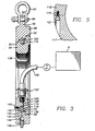
- Fig. 3 is a sectional view taken along the line 3-3 of Fig. 2.
- Fig. 4 is a fragmentary sectional view of the pressure containing sheave mechanism of Fig. 3 which is illustrated in greater detail as compared with Fig. 3.
- Fig. 5 is a fragmentary sectional view of the sheave wheel showing its sectional construction and pinned assembly.
- a well head assembly shown generally at 10 is connected to the upper extremity of a well casing 12 and incorporates at least one safety valve 14 for the purpose of shutting in the well as desired.
- the well head is typically provided with at least one wing valve 16 that controls the flow of production fluid from the well head into a production line 18 extending to a suitable facility for receiving production fluid.
- a wireline riser assembly shown generally at 20 is connected to the upper portion of the well head assembly and is utilized to introduce a wireline tool string or assembly into the well such that it passes through the well head assembly and into the production tubing that extend downwardly to the production zone being produced by the well.
- a wireline operated tool such as a logging tool, perforating gun, etc. is lowered into the well casing or well bore as the case may be by means of a wireline running tool.
- a typical wireline tool assembly such as that shown at 20 will be connected to the well head by means of a union 24 and will include a wireline blowout preventer 26 having two or more wireline rams that are capable of closing and achieving a seal about the wireline 28 that extends through the wireline tool assembly.
- a wireline riser assembly will incorporate upper and lower lubricators 30 and 32 that are interconnected by a lubricator union 34.
- the wireline riser may also incorporate a wireline cutter and safety mechanism shown at 36 which is coupled to the upper lubricator by a connector union 38.
- a coupling 40 is utilized at the upper end of the wireline cutter 36 to provide for connection of a head catcher 42 which automatically receives and restrains the upper portion of the wireline tool head as it is moved to its full extent within the tool riser above the blowout preventer.
- the wireline riser is provided with a pressure containing sheave mechanism which is internally pressure balanced to minimize side loading of the sheave body and housing assembly.
- a pressure containing wireline sheave mechanism shown generally at 44 and representing the preferred embodiment of the invention, is provided at the upper end of the tool riser and is connected to the head catcher 42 by means of a flow tube connector 46 which is shown in greater detail in Fig. 2.
- the pressure containing wireline sheave mechanism incorporates a sheave body 48 which defines a circular internal opening 50 with a portion thereof being internally threaded as shown at 52.
- a circular sheave housing 54 is designed with an external configuration corresponding to the internal configuration of the body opening 50 is retained in immovable assembly with the body by means of an externally threaded section 56 which establishes a threaded connection with internal threaded section 52 of the body.
- the upper portion of the body 48 is provided with a connector projection 58 having a transverse bore 60 through which extends the connector pin 62 of a support shackle 64.
- the connector pin 62 is threaded into the support shackle 64 so that it will not become inadvertently separated from the support shackle or from the transverse bore 60.
- Any suitable support mechanism may be employed for supporting engagement with the support shackle so as to support the pressure containing sheave mechanism in operative relation with the wireline riser apparatus.
- the body defines substantially parallel wireline passages 66 and 68 which are oriented in substantially tangential relation with a circular inner surface 70 which defines a portion of the body opening 50.
- the wireline extending through the passages 66 and 68 also extends through central passages 72 and 74 of flow tube 46 and a grease tube connector 76 which are each disposed in threaded connection with the body via threaded connectors 78 and 80 respectively.
- the flow tube connector 46 is provided with upper and lower carbide inserts 82 and 84 which are secured within respective internally threaded extremities of the flow tube connector by means of retainer screws 86 and 88.
- Seals 90 and 92 are retained within seal grooves at each end of the flow tube connector to establish a high pressure containing seal with the body structure 48 and with the tool riser assembly of the wireline mechanism.
- a coupling 94 shown in Fig. 1, is received in sealed assembly with the grease seal connector 76 and provides for coupling of grease seal conduits 96 and 98 which contain grease for maintaining a seal with the wireline 28.
- the lowermost grease seal conduit 98 is provided with a coupling 100 to which is connected a cable wiper assembly 102 for minimizing grease loss as the wireline cable passes through it.
- the wireline cable passes about a lower orienting sheave 298 and then extends to a conventional winch, not shown, by which it is paid out or taken up during wireline servicing operations.
- the sheave housing 54 defines an internal sheave recess or chamber 104 which is defined generally by parallel radial surfaces 106 and 108 and by an internal generally cylindrical surface 110.
- the internal sheave recess or chamber 104 opens radially outwardly toward the opposed internal surface 70 of the body 48.
- the internal cylindrical surface 110 is centrally grooved as shown at 112 to define a circular bearing track which receives a plurality of spherical bearings 114.
- a circular sheave wheel element 116 having an inner periphery which defines a circular bearing track or race 118 within which the bearings 114 are received to provide bearing support for the inner periphery of the circular sheave wheel 116.
- the outer periphery of the sheave wheel defines a circular wireline groove 120 which is disposed in registry with the wireline passages 66 and 68 of the body 48 so that the wireline 28 is received within the wireline groove 120 as the moving wireline induces rotation to the sheave wheel.
- the sheave wheel 116 is of segmented construction enabling its segments 115 and 117 to be installed within the sheave chamber and interconnected by dowel pins. 119 which are received within drilled assembly holes 121.
- the sheave wheel defines an inner circular flange 123 and an outer circular flange 125 which are located on opposite sides of the circular cable groove 120. As is evident from Fig. 4 the inner flange 123 is of less diameter as compared with the outer flange 125. These differently dimensioned flanges 123 and 125 correspond with the offset of the cylindrical internal surfaces 70 and 71 which are defined within the sheave body 48 on respective inner and outer sides of the cable expansion groove 142. As the sheave housing 54 is separated from the sheave body 48 any wireline cable strands that might extend toward the expansion groove will not become fouled between the sheave wheel and body. The less dimentioned inner flange 123 defines a clearance with the cylindrical internal surface 70 to permit the wireline cable to move laterally along with the sheave housing and sheave during disassembly from body 48 without becoming fouled or damaged.
- a grease fitting 122 having an externally threaded connector 124 which is received within an internally threaded opening located at the inner periphery of the sheave housing 54.
- the grease fitting is connected via a high pressure conduit 126 to a grease pump P, as shown in Fig. 3, which has its suction in communication with a grease reservoir R and its discharge in communication with the high pressure conduit 126.
- the conduit 126 will be a flexible hose capable of withstanding high well pressure for example in the range of 10,000 psi.
- the grease supply conduit 126 may also take any other suitable form without departing from the spirit and scope of this invention.
- the pump P has a discharge pressure which exceeds well pressure so that during operation of the pressure containing sheave mechanism a unidirectional flow of grease will occur from the grease fitting 122 through a grease supply passage 128 into the sheave chamber 110 at a location immediately adjacent the bearing races of the sheave housing and sheave wheel within which the sheave bearings 114 are located.
- a small quantity of grease will continuously be lost by virtue of its adherence to the wireline.
- This grease loss will be continuously replenished by the flow of grease being injected through the grease supply passage 128 to the sheave chamber 110.
- a positive unidirectional flow of grease will occur in a direction toward the wireline groove of the sheave wheel.
- the sheave bearings will therefore remain free of contaminates and will be appropriately lubricated by the grease.
- the service life of the sheave mechanism, being protected by continuously replenished lubrication, will therefore be quite long.
- a pressure containing sheave mechanism which is capable of withstanding high well pressure such as 10,000 psi for example without necessitating the provision of a heavy and bulky sheave construction.
- This feature is attained by providing the sheave and sheave chamber with a substantially pressure balanced condition to minimize pressure induced side loading forces and to insure that the body structure of the sheave mechanism is subjected, for the most part, only to pressure induced hoop stresses which are readily restrained by the sheave body.
- Sealing between the sheave body 48 and the sheave housing 54 is achieved by a pair of circular sealing elements 130 and 132 which are appropriately contained within circular seal grooves 134 and 136 respectively.
- Sealing elements 130 and 132 confine well pressure acting within the housing 48 to the internal surface area 70 that is located between the seals.
- the seals 130 and 132 establish approximately the same diameter offset or differential area between the seals.
- Surface 70 therefore is subjected to pressure induced force acting radially thereon, thereby causing the body structure 48 to be subjected to radially outward pressure induced force or hoop stress which is easily restrained by the body structure.
- the hoop surface area defined by the surface 70 is rather small in comparison to the structural configuration of the body so that the hoop stress is confined to the central portion of the body structure and is easily contained by the hoop integrity of the body 48.
- the inner periphery of the sheave housing 54 defines a plurality of tool recesses 138, as shown in Fig. 3, which receive a spanner tool or other suitable tool for achieving rotation of the sheave housing relative to the body so as to makeup or unthread the threaded connection 56.
- a spanner tool or other suitable tool for achieving rotation of the sheave housing relative to the body so as to makeup or unthread the threaded connection 56.
- one or more retainer screws 140 are secured to the housing in such manner that the heads thereof overlie the circular joint between the body and housing as shown in Fig. 3. It will frequently be desirable to separate the sheave housing 54 from the body 48 while the wireline remains threaded through the passages 66 and 68 of the body.
- the body 48 defines a circular cable expansion groove 142 which is disposed in registry with the external cable recess of the sheave 116.
- the wireline cable may then be shifted radially outwardly into the cable expansion groove 142 to provide clearance for lateral movement of the outer peripheral portions of the sheave housing and sheave while the wireline cable remains threaded through the passages 66 and 68 of the body.
- This feature is realized by providing a grease injection passage 144 in the sheave body 48 which is in communication with the cable expansion groove 142.
- the passage 144 is adapted to receive sealant grease from an internally threaded passage 146 which is normally closed by a threaded closure plug 148. In absence of well pressure within the sheave cavity the closure plug 148 may be removed and a grease injection conduit may be threadedly connected to the body in its place.
- this grease injection conduit will be the supply hose of a hand pump type grease gun which may be employed to manually inject grease into the sheave cavity for enhancing the pressure containment capability of the sheave mechanism.
- the closure plug 148 may be replaced by a conventional grease fitting to which a grease supply hose fitting is connected. Grease can then be injected from a grease gun into the sheave wheel chamber even under high pressure conditions.
Landscapes
- Engineering & Computer Science (AREA)
- Life Sciences & Earth Sciences (AREA)
- Geology (AREA)
- Mining & Mineral Resources (AREA)
- Physics & Mathematics (AREA)
- Environmental & Geological Engineering (AREA)
- Fluid Mechanics (AREA)
- General Life Sciences & Earth Sciences (AREA)
- Geochemistry & Mineralogy (AREA)
- Mechanical Engineering (AREA)
- Pulleys (AREA)
Claims (11)
- Mécanisme de poulie contenant une pression (44) destiné à être utilisé avec un câble de forage s'étendant dans un puits contenant du fluide à haute pression, le mécanisme comportant une première pièce de boítier de poulie (48) et une seconde pièce de boítier de poulie (54), la première pièce de boítier de poulie (48) ayant une ouverture interne circulaire (50) et des premier (66) et second (68) passages de câble de forage recoupant ladite ouverture (50), la seconde pièce de boítier de poulie (54) étant fixée sur la première pièce de boítier de poulie, au moins une partie de la seconde pièce de boítier de poulie étant agencée dans l'ouverture (50) de la première pièce de boítier de poulie (48), et une chambre de poulie annulaire (104) étant disposée de manière étanche entre lesdites pièces de boítier de poulie (48, 54), caractérisé en ce que le mécanisme de poulie comporte :dans lequel l'ouverture (50) de la première pièce de boítier de poulie (48) a une surface cylindrique dirigée radialement vers l'intérieur (110), ladite partie de la seconde pièce de boítier de poulie (54) a une surface cylindrique dirigée radialement vers l'extérieur (70) en vis-à-vis et étroitement adjacente à la surface cylindrique (110) de l'ouverture (50), et ladite chambre de poulie (104) est définie par une gorge en O formée dans l'une desdites surfaces et la partie de l'autre surface située en vis-à-vis de la gorge en O.un élément de poulie annulaire (116) monté coaxialement et de manière rotative dans ladite chambre de poulie (104) et ayant une gorge périphérique dirigée radialement vers l'extérieur (120) en vis-à-vis desdits premier et second passages de câble de forage (66, 68) ;
- Mécanisme de poulie selon la revendication 1, dans lequel des moyens d'étanchéité circulaires respectifs (130, 132) sont agencés entre les pièces de boítier de poulie (48, 54), dans l'ouverture (50), de chaque côté de la gorge définissant la chambre.
- Mécanisme de poulie selon la revendication 1, dans lequel ladite gorge définissant la chambre est formée dans la seconde pièce de boítier de poulie (54).
- Mécanisme de poulie selon la revendication 3, dans lequel la surface cylindrique (110) de la première pièce de boítier de poulie (48) comporte une gorge d'agrandissement de câble de forage (142) s'étendant autour de celui-ci en vis-à-vis de la gorge périphérique (120) de l'élément de poulie (116), pour recevoir le câble de forage et faciliter ainsi la séparation des pièces de boítier de poulie (48, 54).
- Mécanisme de poulie selon l'une quelconque des revendications 1 à 4, dans lequel l'élément de poulie annulaire (116) est formé de deux tronçons pouvant être séparés qui sont fixés l'un à l'autre.
- Mécanisme de poulie selon l'une quelconque des revendications 1 à 5, dans lequel ledit élément de poulie (116) est supporté de manière rotative sur un palier (114) dirigé radialement vers l'intérieur de celui-ci dans ladite chambre (104), et ladite seconde pièce de boítier de poulie (54) comporte un passage de lubrifiant sous pression (128) pour alimenter du lubrifiant vers ledit palier (114).
- Mécanisme de poulie selon la revendication 6, dans lequel ledit palier (114) est un palier à billes.
- Mécanisme de poulie selon la revendication 6, dans lequel ledit palier (114) est un palier à rouleaux.
- Mécanisme de poulie selon l'une quelconque des revendications 6 à 8, comportant de plus une pompe haute pression (P) pour alimenter ledit lubrifiant jusqu'audit palier (114).
- Mécanisme de poulie selon l'une quelconque des revendications précédentes, dans lequel lesdites première et seconde pièces de boítier de poulie (48, 54) sont fixées ensemble par une interconnexion vissée (52, 56).
- Mécanisme de poulie selon l'une quelconque des revendications précédentes, comportant de plus un tube d'écoulement (46) relié à ladite première pièce de boítier de poulie (48) et définissant un autre passage de câble de forage (72) en vis-à-vis de l'un desdits premier et second passages de câble de forage (66, 68), ledit autre passage de câble de forage (72) recevant ledit câble de forage, et des moyens d'étranglement (86, 88) agencés dans ledit tube d'écoulement (46) autour dudit autre passage de câble de forage (72) et limitant l'échappement de lubrifiant à partir de ladite première pièce de boítier de poulie (48) le long dudit câble de forage pendant un fonctionnement dudit mécanisme de poulie (4).
Applications Claiming Priority (3)
| Application Number | Priority Date | Filing Date | Title |
|---|---|---|---|
| US30487694A | 1994-09-13 | 1994-09-13 | |
| US304876 | 1994-09-13 | ||
| PCT/US1995/011038 WO1996008634A1 (fr) | 1994-09-13 | 1995-08-29 | Mecanisme de poulie sous pression pour l'entretien de cables de forage sous haute pression |
Publications (3)
| Publication Number | Publication Date |
|---|---|
| EP0727007A1 EP0727007A1 (fr) | 1996-08-21 |
| EP0727007A4 EP0727007A4 (fr) | 2000-10-04 |
| EP0727007B1 true EP0727007B1 (fr) | 2003-05-14 |
Family
ID=23178368
Family Applications (1)
| Application Number | Title | Priority Date | Filing Date |
|---|---|---|---|
| EP95931648A Expired - Lifetime EP0727007B1 (fr) | 1994-09-13 | 1995-08-29 | Mecanisme de poulie sous pression pour l'entretien de cables de forage sous haute pression |
Country Status (3)
| Country | Link |
|---|---|
| US (1) | US5662312A (fr) |
| EP (1) | EP0727007B1 (fr) |
| WO (1) | WO1996008634A1 (fr) |
Families Citing this family (4)
| Publication number | Priority date | Publication date | Assignee | Title |
|---|---|---|---|---|
| US6177744B1 (en) * | 1998-03-17 | 2001-01-23 | Reliance Electric Technologies, Llc | Seal arrangement for an electric motor |
| US7051803B2 (en) * | 2003-03-24 | 2006-05-30 | Moretz Benny W | Enclosed radial wire-line cable conveying method and apparatus |
| US7434843B1 (en) * | 2004-04-07 | 2008-10-14 | Northrop Grumman Corporation | Hollow shaft fluid rotary joint |
| RU2736743C1 (ru) * | 2020-07-17 | 2020-11-19 | Общество с Ограниченной Ответственностью "ТНГ-Групп" | Устройство для спуска геофизического кабеля «жесткой» конструкции в скважину под большим давлением |
Family Cites Families (9)
| Publication number | Priority date | Publication date | Assignee | Title |
|---|---|---|---|---|
| US2630180A (en) * | 1949-08-15 | 1953-03-03 | Kenneth A Summers | Line feeder for high-pressure oil wells |
| US2677427A (en) * | 1951-02-06 | 1954-05-04 | Shell Dev | Cable injecting device |
| US2720266A (en) * | 1953-10-05 | 1955-10-11 | Shell Dev | Line inserting device for high pressure vessels |
| US2810439A (en) * | 1955-05-11 | 1957-10-22 | Mccullough Otis Johnson | Well head attachment for operating tools in a well under pressure |
| US2943682A (en) * | 1956-01-31 | 1960-07-05 | Bowen Company Of Texas Inc | Wireline control head |
| US3363880A (en) * | 1966-11-14 | 1968-01-16 | Schiumberger Technology Corp | Cable-feeding apparatus |
| US4542787A (en) * | 1984-05-29 | 1985-09-24 | Parker Richard W | Wireline oil pan |
| US5188173A (en) * | 1991-05-21 | 1993-02-23 | Schlumberger Technology Corporation | Pressure control system and cable guiding device for use in drilling wells |
| US5392861A (en) * | 1994-03-07 | 1995-02-28 | Champagne; Paul | Residual pollution containment device and method of cleaning a wireline |
-
1995
- 1995-08-29 EP EP95931648A patent/EP0727007B1/fr not_active Expired - Lifetime
- 1995-08-29 WO PCT/US1995/011038 patent/WO1996008634A1/fr not_active Ceased
-
1996
- 1996-07-22 US US08/686,177 patent/US5662312A/en not_active Expired - Lifetime
Also Published As
| Publication number | Publication date |
|---|---|
| US5662312A (en) | 1997-09-02 |
| WO1996008634A1 (fr) | 1996-03-21 |
| EP0727007A4 (fr) | 2000-10-04 |
| EP0727007A1 (fr) | 1996-08-21 |
Similar Documents
| Publication | Publication Date | Title |
|---|---|---|
| US10087696B2 (en) | Polish rod locking clamp | |
| CA2716430C (fr) | Tete d'entrainement de pompe avec boitier etanche | |
| US3965987A (en) | Method of sealing the annulus between a toolstring and casing head | |
| US4500094A (en) | High pressure rotary stripper | |
| US7080685B2 (en) | High pressure rotating drilling head assembly with hydraulically removable packer | |
| US10087701B2 (en) | Low profile rotating control device | |
| US8627890B2 (en) | Rotating continuous flow sub | |
| US4154448A (en) | Rotating blowout preventor with rigid washpipe | |
| US6896048B2 (en) | Rotary support table | |
| US5332044A (en) | Wellhead isolation tool and method of use | |
| US5383519A (en) | Apparatus for rotating a tubing string of a pumping wellhead | |
| EP0727007B1 (fr) | Mecanisme de poulie sous pression pour l'entretien de cables de forage sous haute pression | |
| US3497244A (en) | Swivel with adjustable packing | |
| US10822908B2 (en) | Continuous circulation system for rotational drilling | |
| US4074775A (en) | Power swivel | |
| US20090101359A1 (en) | High Pressure Wireline Top-Entry Packoff Apparatus and Method | |
| CA3111310A1 (fr) | Joint de dispositif de commande rotatif | |
| RU225933U1 (ru) | Элеватор корпусной | |
| RU2798532C1 (ru) | Герметизатор устьевой роторный | |
| AU2024290266A1 (en) | Boltless sealing assembly securement method | |
| WO1993023654A1 (fr) | Dispositif de commande par le haut |
Legal Events
| Date | Code | Title | Description |
|---|---|---|---|
| PUAI | Public reference made under article 153(3) epc to a published international application that has entered the european phase |
Free format text: ORIGINAL CODE: 0009012 |
|
| AK | Designated contracting states |
Kind code of ref document: A1 Designated state(s): DK FR GB NL |
|
| 17P | Request for examination filed |
Effective date: 19960823 |
|
| RBV | Designated contracting states (corrected) |
Designated state(s): DK FR GB NL |
|
| REG | Reference to a national code |
Ref country code: DE Ref legal event code: 8566 |
|
| A4 | Supplementary search report drawn up and despatched |
Effective date: 20000821 |
|
| AK | Designated contracting states |
Kind code of ref document: A4 Designated state(s): DK FR GB NL |
|
| RIC1 | Information provided on ipc code assigned before grant |
Free format text: 7E 21B 19/08 A, 7E 21B 33/072 B, 7E 21B 19/22 B |
|
| 17Q | First examination report despatched |
Effective date: 20020218 |
|
| GRAH | Despatch of communication of intention to grant a patent |
Free format text: ORIGINAL CODE: EPIDOS IGRA |
|
| GRAH | Despatch of communication of intention to grant a patent |
Free format text: ORIGINAL CODE: EPIDOS IGRA |
|
| GRAA | (expected) grant |
Free format text: ORIGINAL CODE: 0009210 |
|
| AK | Designated contracting states |
Designated state(s): DK FR GB NL |
|
| PG25 | Lapsed in a contracting state [announced via postgrant information from national office to epo] |
Ref country code: NL Free format text: LAPSE BECAUSE OF FAILURE TO SUBMIT A TRANSLATION OF THE DESCRIPTION OR TO PAY THE FEE WITHIN THE PRESCRIBED TIME-LIMIT Effective date: 20030514 Ref country code: FR Free format text: LAPSE BECAUSE OF FAILURE TO SUBMIT A TRANSLATION OF THE DESCRIPTION OR TO PAY THE FEE WITHIN THE PRESCRIBED TIME-LIMIT Effective date: 20030514 |
|
| REG | Reference to a national code |
Ref country code: GB Ref legal event code: FG4D |
|
| PG25 | Lapsed in a contracting state [announced via postgrant information from national office to epo] |
Ref country code: DK Free format text: LAPSE BECAUSE OF FAILURE TO SUBMIT A TRANSLATION OF THE DESCRIPTION OR TO PAY THE FEE WITHIN THE PRESCRIBED TIME-LIMIT Effective date: 20030814 |
|
| PG25 | Lapsed in a contracting state [announced via postgrant information from national office to epo] |
Ref country code: GB Free format text: LAPSE BECAUSE OF NON-PAYMENT OF DUE FEES Effective date: 20030829 |
|
| NLV1 | Nl: lapsed or annulled due to failure to fulfill the requirements of art. 29p and 29m of the patents act | ||
| PLBE | No opposition filed within time limit |
Free format text: ORIGINAL CODE: 0009261 |
|
| STAA | Information on the status of an ep patent application or granted ep patent |
Free format text: STATUS: NO OPPOSITION FILED WITHIN TIME LIMIT |
|
| GBPC | Gb: european patent ceased through non-payment of renewal fee | ||
| 26N | No opposition filed |
Effective date: 20040217 |
|
| EN | Fr: translation not filed |