EP0727093B1 - Tube cathodique couleur et dispositif d'affichage - Google Patents
Tube cathodique couleur et dispositif d'affichage Download PDFInfo
- Publication number
- EP0727093B1 EP0727093B1 EP95927922A EP95927922A EP0727093B1 EP 0727093 B1 EP0727093 B1 EP 0727093B1 EP 95927922 A EP95927922 A EP 95927922A EP 95927922 A EP95927922 A EP 95927922A EP 0727093 B1 EP0727093 B1 EP 0727093B1
- Authority
- EP
- European Patent Office
- Prior art keywords
- cathode ray
- ray tube
- ratio
- display device
- colour
- Prior art date
- Legal status (The legal status is an assumption and is not a legal conclusion. Google has not performed a legal analysis and makes no representation as to the accuracy of the status listed.)
- Expired - Lifetime
Links
Images



Classifications
-
- H—ELECTRICITY
- H01—ELECTRIC ELEMENTS
- H01J—ELECTRIC DISCHARGE TUBES OR DISCHARGE LAMPS
- H01J29/00—Details of cathode-ray tubes or of electron-beam tubes of the types covered by group H01J31/00
- H01J29/02—Electrodes; Screens; Mounting, supporting, spacing or insulating thereof
- H01J29/06—Screens for shielding; Masks interposed in the electron stream
- H01J29/07—Shadow masks for colour television tubes
- H01J29/076—Shadow masks for colour television tubes characterised by the shape or distribution of beam-passing apertures
Definitions
- the invention relates to a colour cathode ray tube comprising an electron gun for generating at least one electron beam, a colour selection electrode having rows of apertures, a display screen and means for deflecting the electron beam across the colour selection electrode in a line deflection direction transverse to the row of apertures.
- Such display devices are known. They are used, inter alia, in television receivers.
- Moiré effect causes light and dark bands or bands of a deviating colour in the image.
- lines are written on the display screen in the line deflection direction by the electron beam(s).
- the number of lines written on the display screen (the so-called number of active lines) is system-dependent.
- the NTSC system approximately 452 active lines are written (the NTSC signal comprises 525 lines).
- MUSE scan-mode the number of active scan lines is approximately 967.
- a colour cathode ray tube preferably does not exhibit disturbing Moire effects for display, irrespective of whether such a tube is used in different systems such as PAL, SECAM, NTSC or MUSE systems.
- the colour cathode ray tube in accordance with the invention is characterized in that the number of apertures per row ranges between 615 and 650, or between 425 to 450.
- the invention further aims at providing a display device comprising a colour cathode ray tube in accordance with the invention and means for receiving a television signal.
- the display device in accordance with the invention is characterized in that, in operation, the so-called s/a v ratio, where s is the scan pitch for the entire frame and a v is the vertical mask pitch, is between 9.2/8 and 9.6/8 for a PAL-system and preferably between 9.3/8 and 9.5/8 for the PAL-system or between 6-5/8 and 6-8/8.
- the corresponding values of the s/a v ratio for a NTSC system are between 10.91/8 and 11.38/8 and for the MUSE system between 5.11/8 and 5.33/8.
- a PAL (SECAM), NTSC or MUSE display device is to be understood to mean within the scope of the invention a display device which is suitable for receiving, respectively, a PAL (SECAM), an NTSC or MUSE signal.
- An embodiment in which the aspect ratio of the cathode ray tube in the display system is approximately 16:9 comprises means to display on the screen a received signal in an expanded mode in such manner that the s/a v ratio ranges between 10.7/8 and 11.3/8 for a PAL system or between 12.7/8 and 13.4/8 for a NTSC system.
- An embodiment in which the aspect ratio of the cathode ray tube in the display system is approximately 4:3 comprises means to display on the screen a received signal in an compressed mode in such manner that the s/a v ratio ranges between 8.9/8 and 9.6/8 for a NTSC system.
- the inventors have furthermore realized that there is also a need for colour cathode ray tubes that can be used in display devices which receive a television signal but can also be used in personal computers or graphic displays.
- the number of lines written on the screen for such systems differ from the PAL, SECAM, NTSC and MUSE systems.
- the number of lines written on the screen equal to 480, 600 and 768 for the so-called VGA, SVGA and XGA scan modes, respectively.
- Known colour cathode ray tubes when used in a display system for receiving a television signal for instance a PAL signal with approximately 537 written lines, below for simplicity also indicated as a television mode
- a display systems for graphic display using for instance a SVGA system with approximately 645 written lines, below for simplicity also indicated as a graphic mode
- the cathode ray tube in accordance with the first aspect of the invention can also be used in graphic display systems using the VGA or XGA system.
- the inventors have realized that apart from the cathode ray tube in accordance with the first aspect of the invention it is possible to achieve a cathode ray tube which can be used in a PAL system television display system as well as in most graphic display systems, including a SVGA system.
- a colour cathode ray tube in accordance with the invention is characterized in that the number of apertures per row ranges between 425 and 450, preferably 435 and 450.
- Such a colour cathode ray tube shows little or no Moiré patterns when used in a PAL system, as well as when used in the VGA or SVGA graphic modes. This enables one and the same colour display tube to be used in graphic display devices as well as in television sets. Significant savings in manufacturing costs can thereby be achieved.
- Fig. 1 is a partly perspective view of a cathode ray tube 1.
- Said cathode ray tube 1 comprises an evacuated envelope 3 having a display window 2, and a neck 4.
- an electron gun 5 for generating, in this example, three electron beams 6, 7 and 8.
- a luminescent display screen 9 which, in this example, comprises phosphor elements luminescing in red, green and blue.
- said electron beams 6, 7 and 8 are deflected across the screen 9 by means of a deflection unit 10, which is located at the junction between the neck and the cone, and pass through the colour selection electrode, in this example the shadow mask 11 which comprises a thin plate having apertures 12.
- the electron beams 6, 7 and 8 pass through said apertures 12 at a small angle with respect to each other and each electron beam impinges on phosphor elements of only one colour.
- Said Figure also diagrammatically shows the drive mechanism 14 of the electron gun and the deflection unit as well as the receiving means 15 for receiving a signal 16.
- the receiving means are capable of receiving a PAL, SECAM, NTSC or MUSE television signal.
- Fig. 2 is a top view of a detail of a colour selection electrode.
- Said colour selection electrode comprises a number of rows of apertures 21. Said rows extend transversely to the line deflection direction x. In successive rows the apertures are offset relative to each other in a direction transverse to the line deflection direction. Scanning lines 22 are also shown. The direction transverse to the line deflection direction is also called the field deflection direction. In most cathode ray tubes and display systems the field deflection direction is the vertical direction and the line deflection direction is the horizontal direction. The rows of apertures are therefore aligned in the vertical direction. Said scanning lines diagrammatically show where the electron beam(s) is (are) incident on the shadow mask.
- the number of lines which are incident on the shadow mask and which impinges on the display screen after passing through the apertures of the shadow mask is approximately 537.
- the number of active lines of the NTSC system used e.g. in the USA is approximately 452.
- the scanning-line pitch s is shown. This is the distance between the scanning lines.
- the distance between the apertures (vertical mask pitch) a v is also shown.
- Moiré effects occur in horizontal directions (in which case horizontal bars are visible in the image displayed) and at oblique angles (oblique bars appear in the image). Combinations thereof, which appear for example in the form of a diamond pattern, are also possible. In each of the systems (PAL-SECAM; NTSC, MUSE) different Moiré effects occur.
- the invention makes it possible to provide a colour cathode ray tube which can be used in the various existing systems and applications without the occurrence of disturbing Moiré effects. By virtue thereof, a substantial saving in costs can be achieved; in various types of display devices the same colour-cathode ray tube can be used. It is also possible to use the same colour selection electrode for different types of colour cathode ray tubes.
- the invention also provides a cathode ray tube which does not exhibit disturbing Moiré patterns when it is used for PAL (SECAM), NTSC or MUSE system. Regional restriction for use of a colour cathode ray tube in a television system are removed in a cathode ray tube according to the first aspect of the invention.
- the colour cathode ray tube in accordance with the invention is characterized in that the number of apertures per row ranges between 615 and 650, and preferably between 625 and 635. This corresponds to an s/a v ratio (where s is the scan pitch for the entire frame and a v is the mask pitch) between 9.2/8 and 9.6/8 for a PAL-system and preferably between 9.3/8 and 9.5/8 for the PAL-system.
- the corresponding ranges for the s/a v ratio for a NTSC system are between 10.91/8 and 11.38/8 and for the MUSE system between 5.11/8 and 5.33/8.
- a PAL (SECAM), NTSC or MUSE display device is to be understood to mean within the scope of the invention a display device which is suitable for receiving, respectively, a PAL (SECAM), an NTSC or MUSE signal.
- the invention is in particular useful for large screen devices (larger than 50 cm) and also for wide screen devices (devices with a aspect ratio larger than 4:3, for instance 16:9).
- the invention also relates to a display device comprising such a colour cathode ray tube.
- the s/a v ratio is best at 9.4 ( ⁇ 0.2)/8 corresponding to a number of apertures of between approximately 615 and 650.
- Lower values including the hitherto believed "optimal value" of 9/8
- 9/8 will increase the still-picture Moiré effect resulting in a deterioration of the picture quality.
- an s/a v value between 9.2/8 and 9.3/8 would be optimal.
- raster distortion means that over the mask the s/a v ratio shows a variation.
- An increase of the s/a v ratio to higher values than 9.2-9.3/8 leads to less disturbing Moiré effects than a decrease below said values.
- the s/a v ratio is somewhat higher than 9.3/8 in order to create a "safety margin". Values for s/a v higher than 9.6/8, however, could introduce motion Moiré.
- the indicated values for the s/a v ratio (between 9.2/8 and 9.6/8) for the PAL-system correspond to s/a v values for the NTSC system between 10.91/8 and 11.38/8 and for the MUSE system between 5.11/8 and 5.38/8.
- the s/a v range between 8/8 and 10/8 i.e. that within the frame-work of the invention is has been realized that the s/a v range used should be chosen very asymmetrical with respect to the "forbidden” values 8/8 and 10/8, and more in particular closer to 10/8 than to 8/8, also holds for the s/a v value range between 4/8 and 6/8.
- the "best" range in between 4/8 and 6/8 lies much closer to 6/8 than to 4/8 which is indeed the case for the above given range 5.11/8-5.33/8 (MUSE).
- a further aspect of the invention is that it has been recognized that the s/a v ratio 12/8 is also much less forbidden than 8/8. Somewhat larger s/a v ratios, more close to 12/8, for NTSC application, according to the invention in the range 10.91/8 to 11.38/8 therefore also result in a reduction of Moiré.
- having the number of apertures between 615 and 650 and preferably between 625 and 635 provides a cathode ray tube which can advantageously be used in PAL, SECAM, NTSC as well as MUSE systems.
- the lines can be scanned in the so-called interlace manner, in which first the even or odd lines are scanned, whereafter the other lines are scanned, or the lines can be scanned progressively.
- FIG. 3A shows a wide screen display device on which a 4:3 image is displayed.
- the s/av ratio also changes by a factor 4:3.
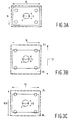
- Figures 3A to 3D illustrate aspects of the invention relating to the display of 4:3 images on a 16:9 screen.
- Figure 3A shows for a PAL system the dimensions of an image broadcast in the 4:3 format, when displayed on a 16:9 screen and expanded only in the horizontal direction. The screen is indicated by full lines, the image displayed on the screen by dotted lines. Since there is usually an overscan the dotted lines extend slightly beyond the full lines.
- the original, undistorted image comprised five circles, one in the centre of the image and one at each corner.
- the image is portrayed in a distorted manner, where the circles have become ovals, the ratio of height and width of the ovals being 3:4.
- the width is in this figure indicated by 4 and the height by 3.
- FIG. 3B shows the conventional manner of dealing with this problem.
- the image is expanded in the vertical direction (by means of increasing the line spacing s) by a factor of 1.333.
- Figure 3C shows an aspect of the invention. In this figure the image is also expanded in the vertical direction by a smaller factor.
- the expansion factor is established that the for a PAL or SECAM system the resulting s/a v ratio ranges between 10.7/8 to 11.3/8 and for the NTSC system the resulting s/a v ratio ranges between 12.7/8 and 13.4/8.
- the resulting expansion factor ranges approximately, to same extent depending on the s/a v ratio in the non-expanded mode and the system, between 1.15 and 1.25 instead of being 1.33.
- the decreased expansion of the image in the vertical direction has several advantages.
- the number of lines (and thus the extent in which the image is not displayed) that is lost is less, since whereas in the conventional system 33% of the originally displayed image is lost, in a device according to the invention only about 20% of said image is lost.
- the parts of the image that are lost are indicated by Al and B1. Clearly it can be seen that the areas B in figure 3C are smaller than the areas A in figure 3B.
- the s/a v ratio has decreased from approximately 12.5/8 (for the PAL system) and 14.7/8 (for the NTSC system) in figure 3B to approximately 11/8 (PAL) and 13/8 (NTSC) in figure 3C.
- a further advantageous effect is that the ability to display fine details is improved.
- the dimensions of the displayed image are 4 (width): 3.6 (height).
- FIG. 3E An alternative is shown in figure 3E.
- the horizontal dimension is however somewhat expanded. This result in a perfect image at the centre but a somewhat distorted image at the edges of the screen, while the image completely fills the screen.
- the image therefore is subjected to an increase in the s/a v ratio (by approximately 1.15 to 1.25) combined with a panoramic distortion in the horizontal direction.
- FIG. 4A shows an 16:9 image displayed on a 4:3 screen.
- the image is clearly distorted.
- a conventional manner of solving this problem is compressing the image in the vertical direction by a factor of 1.33.
- Figure 4B show the resulting image. Black bars occur at above and below the image.
- reducing the vertical dimensions of the image displayed by a factor of 1.33 would reduce the s/a v from between 10.91/8 and 11.38/8 to between 8.2/8 to 8.5/8. For these s/a v ratios severe Moiré effects occur.
- a display system of the NTSC type having a cathode ray tube with screen with an aspect ratio of 4:3 comprises means for compressing in the vertical direction the image displayed on the screen in such manner that the s/a v ranges between 8.9/8 and 9.6/8. For these s/a v ratio almost no Moiré effects occur.
- the vertical dimensions of the image are then reduced by a factor of approximately 1.2. Any resulting distortion of the image can, if wanted, be reduced or overcome by an expansion of the image in the horizontal direction.
- the resulting image (without expansion in the horizontal direction) is shown in figure 4C. Apart from the fact that much less Moiré effects occur a further advantage is that the black bars are much smaller.
- Figures 3A to 4C therefore illustrate aspects of the invention relating to problems which occur when an image of a certain aspect ratio as to be displayed on a display screen of a different (larger or smaller size).
- the expansion or compression factor for the horizontal direction to be between 1.15 and 1.25 instead of the conventional 1.33 a more advantageous s/a v ratio (in regards of Moiré effects) as well as a better filling of the screen results.
- the inventors have furthermore realized that there is also a need for colour cathode ray tubes which can be used in display devices which receive a television signal but can also be used in personal computers or graphic displays.
- the number of lines written on the screen for such personal computer or graphic display systems differs from the PAL, SECAM, NTSC and MUSE systems.
- the number of lines written over the full screen are approximately (taken into account the fact that for graphic display purposes conventionally a underscan of approximately 8% is applied) 520 for the VGA system, approximately 650 for the SVGA system and approximately 830 for the so-called XGA system.
- Known colour cathode ray tubes when used in a display system for receiving a television signal for instance a PAL signal with approximately 537 written lines
- a display systems for graphic display using for instance a VGA system with approximately 520 written lines
- the colour cathode ray tube according to the first aspect of the invention shows little or no Moiré patterns for the VGA and for the XGA systems and can therefore be used in a very wide range of applications, both regionally and as far as applications is concerned.
- the inventors have realized that apart from the cathode ray tube in accordance with the first aspect of the invention it is possible to achieve a cathode ray tube which can be used in a PAL system television display system as well as in some graphic display systems although it is less suitable for SVGA.
- a colour cathode ray tube in accordance with a second aspect of the invention is characterized in that the number of apertures per row ranges between 425 and 450, preferably 435 and 450.
- Such a colour cathode ray tube shows little or no Moire patterns when used in a PAL or SECAM system, or when used in the VGA or SVGA graphic modes.
- This enables one and the same colour display tube to be used in graphic display devices as well as in television sets. Significant savings in manufacturing costs can thereby be achieved.
- the s/a v ratios lie between 6.5/8 to 6.8/8 for a PAL system between 6.7/8 and 7/8 when used in the VGA graphic mode and between 5.35/8 to 5.6/8 when used in a SVGA graphic mode. Although none of these ratios corresponds exactly to an ideal ratio according to the hitherbefore accepted theory in each of the indicated modes the s/a v ratio is such that no or hardly any Moire patterns occur.
- This aspect of the invention enables at least regionally (in those countries where the PAL or SECAM system is used) to remove restriction in the type of systems (television or graphic display systems) in which the cathode ray tube can be used.
- the range 425 - 435 is advantageous if a VGA, SVGA or XGA system is used with less then conventional underscan, e.g. 4 - 5%. Less than conventional underscan has the advantage that more efficient use is made of the available phosphor screen area.
- the colour cathode ray tube according to the first aspect of the invention (a colour cathode ray tube having between 615 and 650 apertures per vertical row) is suitable for use in the VGA and XGA mode since the s/a v ratios for these modes are between approximately 9.5/8 and 10/8 (VGA) and approximately 5.9/8 and 6.3/8 (XGA). For these ranges little or no Moiré effects occur.
- Tables 1 and 2 summarize the different aspects of the present invention.
- Table 1 illustrates that depending on the number of apertures in the shadow mask a colour cathode ray tube according to the present invention can be used in several systems and modes.
- Table 2 summarizes the different systems and the corresponding s/a v ratios in non-expanded as well as in expanded modes or compressed modes, where expansion and compression relates to the vertical direction. cathode ray tubes according to the invention and their use in display systems.
- Cathode ray tube (number of apertures per vertical row indicated) suitable for the systems (approximate s/a v ratio in standard mode indicated in parentheses) 615-650 PAL (9.2/8-9.6/8), NTSC (10.9/8-11.38/8), MUSE (5.11/8-5.33/8), VGA (9.5/8-10/8), XGA (5.9/8-6.3/8) 435-450 PAL (6.5/8-6.8/8), VGA (6.7/8-7/8), SVGA (5.35/8-5.6/8) Television display systems according to the invention with s/a v ratio in standard and expanded or compressed mode, according to embodiments of the invention.
- system aspect ratio s/a v ratio PAL/SECAM any 9.2/8-9.6/8 larger than 4:3, in particular 16:9 9.2/8-9.6/8 (standard mode) 10.7/8-11.3/8 (expanded mode) NTSC any 10.9/8-11.38/8 larger than 4:3 in particular 16:9 10.9/8-11.38/8 (standard mode) 12.7/8-1.4/8 (expanded mode) approximately 4:3 10.9/8-11.38/8 (standard mode) 8.9/8-9.6/8 (compressed mode) MUSE any 5.11/8-5.33/8 PAL/SECAM any 6.5/8-6.8/8
- the number of apertures per vertical row in the shadow mask of a colour cathode ray tube can be in the range between 615 and 650, such a cathode ray tube can be used in many systems, including the PAL, NTSC and MUSE systems as well as in several systems used for graphic displays without the occurrence of disturbing Moiré effects.
- the number of apertures per row ranges between 425 - 450, preferably between 435 and 450.
- Such a colour cathode ray tube can be used in a PAL system as well as in several graphic display systems.
Landscapes
- Television Systems (AREA)
- Vessels, Lead-In Wires, Accessory Apparatuses For Cathode-Ray Tubes (AREA)
- Transforming Electric Information Into Light Information (AREA)
Claims (9)
- Tube cathodique couleur (1) comprenant un canon à électrons pour générer (5) au moins un faisceau électronique (6, 7, 8), une électrode de sélection de couleur (11) comportant des rangées (21) d'ouvertures (12), un écran d'affichage (9) et des moyens (10) pour dévier le ou les faisceaux électroniques en travers de l'électrode de sélection de couleur dans une direction de déviation de ligne transversale à la rangées d'ouvertures, caractérisé en ce que le nombre d'ouvertures par rangée est compris entre 615 et 650, ou entre 425 et 450.
- Tube cathodique couleur suivant la revendication 1, caractérisé en ce que le nombre d'ouvertures par rangée est compris entre 625 et 635, ou entre 435 et 450.
- Dispositif d'affichage du type PAL ou SECAM comprenant un tube cathodique couleur suivant la revendication 1 ou 2 et des moyens (15) pour recevoir un signal de télévision PAL ou SECAM (16), caractérisé en ce que, en fonctionnement, le rapport s/av, où s est le pas de balayage pour la trame entière et av est le pas de masque vertical, est compris entre 9,2/8 et 9,6/8 ou entre 6,5/8 et 6,8/8.
- Dispositif d'affichage suivant la revendication 3, caractérisé en ce que le rapport s/av est compris entre 9,3/8 et 9,5/8.
- Dispositif d'affichage suivant la revendication 3 ou 4, caractérisé en ce que le tube cathodique couleur comprend un écran d'affichage avec un format d'image supérieur à 4:3 et le dispositif d'affichage comprend des moyens pour dilater dans la direction de déviation de trame l'image affichée sur l'écran de manière telle que le rapport s/av de l'image affichée dans le mode dilaté soit compris entre 10,7/8 et 11,3/8.
- Dispositif d'affichage du type NTSC comprenant un tube cathodique couleur suivant la revendication 1 ou 2 et des moyens (15) pour recevoir un signal de télévision NTSC (16), caractérisé en ce que, en fonctionnement, le rapport s/av, où s est le pas de balayage de l'image entière et av est le pas de masque vertical, est compris entre 10,9/8 et 11,38/8.
- Dispositif d'affichage suivant la revendication 6, caractérisé en ce que le tube cathodique couleur comprend un écran d'affichage avec un format d'image supérieur à 4:3 et le dispositif d'affichage comprend des moyens pour dilater dans la direction de déviation de trame l'image affichée sur l'écran de manière telle que le rapport s/av de l'image dilatée soit compris entre 12,7/8 et 13,4/8.
- Dispositif d'affichage suivant la revendication 6, caractérisé en ce que le tube cathodique couleur comprend un écran d'affichage avec un format d'image d'approximativement 4:3 et le dispositif d'affichage comprend des moyens pour comprimer dans la direction de déviation de trame l'image affichée sur l'écran un signal reçu de manière telle que le rapport s/av des images comprimées soit compris entre 8,9/8 et 9,6/8.
- Dispositif d'affichage du type MUSE comprenant un tube cathodique couleur suivant la revendication 1 ou 2 et des moyens (15) pour recevoir un signal de télévision MUSE (16), caractérisé en ce que, en fonctionnement, le rapport s/av, où s est le pas de balayage de l'image entière et av est le pas de masque vertical , est compris entre 5,11/8 et 5,33/8.
Priority Applications (1)
| Application Number | Priority Date | Filing Date | Title |
|---|---|---|---|
| EP95927922A EP0727093B1 (fr) | 1994-09-07 | 1995-08-28 | Tube cathodique couleur et dispositif d'affichage |
Applications Claiming Priority (6)
| Application Number | Priority Date | Filing Date | Title |
|---|---|---|---|
| EP94202560 | 1994-09-07 | ||
| EP94202560 | 1994-09-07 | ||
| EP95202148 | 1995-08-07 | ||
| EP95202148 | 1995-08-07 | ||
| EP95927922A EP0727093B1 (fr) | 1994-09-07 | 1995-08-28 | Tube cathodique couleur et dispositif d'affichage |
| PCT/IB1995/000697 WO1996008030A1 (fr) | 1994-09-07 | 1995-08-28 | Tube cathodique couleur et dispositif d'affichage |
Publications (2)
| Publication Number | Publication Date |
|---|---|
| EP0727093A1 EP0727093A1 (fr) | 1996-08-21 |
| EP0727093B1 true EP0727093B1 (fr) | 1998-11-04 |
Family
ID=26136557
Family Applications (1)
| Application Number | Title | Priority Date | Filing Date |
|---|---|---|---|
| EP95927922A Expired - Lifetime EP0727093B1 (fr) | 1994-09-07 | 1995-08-28 | Tube cathodique couleur et dispositif d'affichage |
Country Status (7)
| Country | Link |
|---|---|
| US (1) | US5825435A (fr) |
| EP (1) | EP0727093B1 (fr) |
| KR (1) | KR100350818B1 (fr) |
| CN (1) | CN1082239C (fr) |
| BR (1) | BR9506356A (fr) |
| DE (1) | DE69505785T2 (fr) |
| WO (1) | WO1996008030A1 (fr) |
Families Citing this family (5)
| Publication number | Priority date | Publication date | Assignee | Title |
|---|---|---|---|---|
| US5841247A (en) * | 1995-11-24 | 1998-11-24 | U.S. Philips Corporation | Cathode ray tube, display system incorporating same and computer including control means for display system |
| KR100268061B1 (ko) * | 1998-08-20 | 2000-10-16 | 윤종용 | 비디오 포맷 모드 검출기 |
| KR100331812B1 (ko) * | 1999-12-09 | 2002-04-09 | 구자홍 | 평면 브라운관용 새도우마스크 |
| KR100403703B1 (ko) | 2000-01-28 | 2003-11-01 | 삼성에스디아이 주식회사 | 모아레가 개선된 음극선관 |
| WO2001071764A1 (fr) * | 2000-03-20 | 2001-09-27 | Koninklijke Philips Electronics N.V. | Tube cathodique couleur |
Family Cites Families (15)
| Publication number | Priority date | Publication date | Assignee | Title |
|---|---|---|---|---|
| US4326147A (en) * | 1975-08-18 | 1982-04-20 | Hitachi, Ltd. | Slotted shadow mask having apertures spaced to minimize moire |
| US4210842A (en) * | 1975-09-10 | 1980-07-01 | Hitachi, Ltd. | Color picture tube with shadow mask |
| JPS57163955A (en) * | 1981-02-25 | 1982-10-08 | Toshiba Corp | Mask focusing type color picture tube |
| US4638452A (en) * | 1984-02-27 | 1987-01-20 | Allen-Bradley Company, Inc. | Programmable controller with dynamically altered programmable real time interrupt interval |
| JP2531214B2 (ja) * | 1987-12-17 | 1996-09-04 | 三菱電機株式会社 | シャドウマスク形カラ―受像管 |
| US4853592A (en) * | 1988-03-10 | 1989-08-01 | Rockwell International Corporation | Flat panel display having pixel spacing and luminance levels providing high resolution |
| US4942332A (en) * | 1988-12-02 | 1990-07-17 | Zenith Electronics Corporation | Tied slit mask for color cathode ray tubes |
| US5151978A (en) * | 1990-03-22 | 1992-09-29 | Square D Company | Lan interface which permits a host computer to obtain data without interrupting a ladder program executing in the interface |
| US5055736A (en) * | 1990-03-30 | 1991-10-08 | Samsung Electron Devices Co., Ltd. | Shadow mask for use in a three-gun color picture tube |
| BE1004928A3 (nl) * | 1992-01-08 | 1993-02-23 | Burndy Electra Nv | Werkwijze voor het besturen van een systeem met behulp van een computer. |
| IT1254811B (it) * | 1992-02-20 | 1995-10-11 | Videocolor Spa | Tubo di riproduzione di immagini a colori, del tipo a maschera d'ombra, con un effetto di marezzatura ridotto. |
| BE1007430A3 (nl) * | 1993-08-02 | 1995-06-13 | Philips Electronics Nv | Kleurenkathodestraalbuis en beeldweergeefinrichting. |
| IT1269426B (it) * | 1994-01-14 | 1997-04-01 | Videocolor Spa | Tubo per la riproduzione di immagini a colori, con ridotta marezzatura primaria e secondaria |
| KR100351217B1 (ko) * | 1994-10-05 | 2002-12-28 | 코닌클리케 필립스 일렉트로닉스 엔.브이. | 칼라음극선관및디스플레이장치 |
| US5534746A (en) * | 1995-06-06 | 1996-07-09 | Thomson Consumer Electronics, Inc. | Color picture tube having shadow mask with improved aperture spacing |
-
1995
- 1995-08-28 CN CN95191041A patent/CN1082239C/zh not_active Expired - Fee Related
- 1995-08-28 WO PCT/IB1995/000697 patent/WO1996008030A1/fr not_active Ceased
- 1995-08-28 BR BR9506356A patent/BR9506356A/pt not_active IP Right Cessation
- 1995-08-28 EP EP95927922A patent/EP0727093B1/fr not_active Expired - Lifetime
- 1995-08-28 DE DE69505785T patent/DE69505785T2/de not_active Expired - Fee Related
- 1995-08-28 KR KR1019960702380A patent/KR100350818B1/ko not_active Expired - Fee Related
- 1995-08-31 US US08/522,035 patent/US5825435A/en not_active Expired - Fee Related
Also Published As
| Publication number | Publication date |
|---|---|
| DE69505785D1 (de) | 1998-12-10 |
| WO1996008030A1 (fr) | 1996-03-14 |
| CN1137327A (zh) | 1996-12-04 |
| EP0727093A1 (fr) | 1996-08-21 |
| BR9506356A (pt) | 1997-09-16 |
| CN1082239C (zh) | 2002-04-03 |
| KR100350818B1 (ko) | 2002-12-31 |
| US5825435A (en) | 1998-10-20 |
| DE69505785T2 (de) | 1999-06-02 |
Similar Documents
| Publication | Publication Date | Title |
|---|---|---|
| Ciciora | Twenty-Four Rows of Videotex in 525 Scan Lines | |
| EP0392611B1 (fr) | Dispositif reproducteur d'images | |
| EP0731980B1 (fr) | Tube a rayons cathodiques couleur et dispositif d'affichage | |
| EP0727093B1 (fr) | Tube cathodique couleur et dispositif d'affichage | |
| US5319280A (en) | Color picture tube with reduced raster distortion and flat appearing display window | |
| EP0637833B1 (fr) | Tube à rayons cathodiques en couleurs | |
| CA2139093C (fr) | Tube image couleur a moirages primaire et secondaire reduits | |
| KR100400777B1 (ko) | 칼라 음극선관용 새도우마스크 | |
| US6624557B2 (en) | Cathode-ray tube with reduced moiré effect and a particular ratio of scanning pitches to aperture pitches | |
| EP0806026A2 (fr) | Systeme d'affichage comprenant un tube a rayons cathodiques ainsi qu'un ordinateur presentant des moyens d'envoi d'un signal a un tel systeme d'affichage | |
| JPH09505454A (ja) | カラー陰極線管及び表示装置 | |
| US3439207A (en) | Color tube with shadow mask aper tures and color dots related to permit use in systems having different numbers of scanning lines | |
| JPH09506497A (ja) | カラー陰極線管及びディスプレイ装置 | |
| KR0141540B1 (ko) | 감소된 제 1 및 제 2 무아레를 갖는 칼라수상관 | |
| KR19990000255A (ko) | 멀티미디어용 음극선관 및 그 제조방법 | |
| CN1087889C (zh) | 半宽画面电视接收机 | |
| JPH0729526A (ja) | カラー受像管装置 | |
| JPH0758970A (ja) | カラー受像管装置 | |
| JPH04186972A (ja) | カラー受像装置 | |
| JPH09213229A (ja) | シャドウマスク型カラー陰極線管及び陰極線管装置 | |
| JPH06338272A (ja) | カラー受像管装置 |
Legal Events
| Date | Code | Title | Description |
|---|---|---|---|
| PUAI | Public reference made under article 153(3) epc to a published international application that has entered the european phase |
Free format text: ORIGINAL CODE: 0009012 |
|
| AK | Designated contracting states |
Kind code of ref document: A1 Designated state(s): DE FR GB IT |
|
| 17P | Request for examination filed |
Effective date: 19960916 |
|
| 17Q | First examination report despatched |
Effective date: 19970619 |
|
| GRAG | Despatch of communication of intention to grant |
Free format text: ORIGINAL CODE: EPIDOS AGRA |
|
| GRAG | Despatch of communication of intention to grant |
Free format text: ORIGINAL CODE: EPIDOS AGRA |
|
| GRAH | Despatch of communication of intention to grant a patent |
Free format text: ORIGINAL CODE: EPIDOS IGRA |
|
| GRAH | Despatch of communication of intention to grant a patent |
Free format text: ORIGINAL CODE: EPIDOS IGRA |
|
| GRAA | (expected) grant |
Free format text: ORIGINAL CODE: 0009210 |
|
| AK | Designated contracting states |
Kind code of ref document: B1 Designated state(s): DE FR GB IT |
|
| PG25 | Lapsed in a contracting state [announced via postgrant information from national office to epo] |
Ref country code: IT Free format text: LAPSE BECAUSE OF FAILURE TO SUBMIT A TRANSLATION OF THE DESCRIPTION OR TO PAY THE FEE WITHIN THE PRESCRIBED TIME-LIMIT;WARNING: LAPSES OF ITALIAN PATENTS WITH EFFECTIVE DATE BEFORE 2007 MAY HAVE OCCURRED AT ANY TIME BEFORE 2007. THE CORRECT EFFECTIVE DATE MAY BE DIFFERENT FROM THE ONE RECORDED. Effective date: 19981104 |
|
| REF | Corresponds to: |
Ref document number: 69505785 Country of ref document: DE Date of ref document: 19981210 |
|
| ET | Fr: translation filed | ||
| PLBE | No opposition filed within time limit |
Free format text: ORIGINAL CODE: 0009261 |
|
| STAA | Information on the status of an ep patent application or granted ep patent |
Free format text: STATUS: NO OPPOSITION FILED WITHIN TIME LIMIT |
|
| 26N | No opposition filed | ||
| REG | Reference to a national code |
Ref country code: GB Ref legal event code: IF02 |
|
| PGFP | Annual fee paid to national office [announced via postgrant information from national office to epo] |
Ref country code: FR Payment date: 20060828 Year of fee payment: 12 |
|
| PGFP | Annual fee paid to national office [announced via postgrant information from national office to epo] |
Ref country code: GB Payment date: 20060829 Year of fee payment: 12 |
|
| PGFP | Annual fee paid to national office [announced via postgrant information from national office to epo] |
Ref country code: DE Payment date: 20061013 Year of fee payment: 12 |
|
| GBPC | Gb: european patent ceased through non-payment of renewal fee |
Effective date: 20070828 |
|
| REG | Reference to a national code |
Ref country code: FR Ref legal event code: ST Effective date: 20080430 |
|
| PG25 | Lapsed in a contracting state [announced via postgrant information from national office to epo] |
Ref country code: DE Free format text: LAPSE BECAUSE OF NON-PAYMENT OF DUE FEES Effective date: 20080301 |
|
| PG25 | Lapsed in a contracting state [announced via postgrant information from national office to epo] |
Ref country code: FR Free format text: LAPSE BECAUSE OF NON-PAYMENT OF DUE FEES Effective date: 20070831 |
|
| PG25 | Lapsed in a contracting state [announced via postgrant information from national office to epo] |
Ref country code: GB Free format text: LAPSE BECAUSE OF NON-PAYMENT OF DUE FEES Effective date: 20070828 |