EP0727227A1 - Verfahren und Vorrichtung zum Hochdrucksterilisieren von Produkten - Google Patents
Verfahren und Vorrichtung zum Hochdrucksterilisieren von Produkten Download PDFInfo
- Publication number
- EP0727227A1 EP0727227A1 EP96400241A EP96400241A EP0727227A1 EP 0727227 A1 EP0727227 A1 EP 0727227A1 EP 96400241 A EP96400241 A EP 96400241A EP 96400241 A EP96400241 A EP 96400241A EP 0727227 A1 EP0727227 A1 EP 0727227A1
- Authority
- EP
- European Patent Office
- Prior art keywords
- chamber
- product
- sterilized
- volume
- piston
- Prior art date
- Legal status (The legal status is an assumption and is not a legal conclusion. Google has not performed a legal analysis and makes no representation as to the accuracy of the status listed.)
- Withdrawn
Links
Images


Classifications
-
- A—HUMAN NECESSITIES
- A23—FOODS OR FOODSTUFFS; TREATMENT THEREOF, NOT COVERED BY OTHER CLASSES
- A23B—PRESERVATION OF FOODS, FOODSTUFFS OR NON-ALCOHOLIC BEVERAGES; CHEMICAL RIPENING OF FRUIT OR VEGETABLES
- A23B2/00—Preservation of foods or foodstuffs, in general
- A23B2/10—Preservation of foods or foodstuffs, in general by treatment with pressure variation, shock, acceleration or shear stress
- A23B2/103—Preservation of foods or foodstuffs, in general by treatment with pressure variation, shock, acceleration or shear stress using sub- or super-atmospheric pressures, or pressure variations transmitted by a liquid or gas
-
- A—HUMAN NECESSITIES
- A61—MEDICAL OR VETERINARY SCIENCE; HYGIENE
- A61L—METHODS OR APPARATUS FOR STERILISING MATERIALS OR OBJECTS IN GENERAL; DISINFECTION, STERILISATION OR DEODORISATION OF AIR; CHEMICAL ASPECTS OF BANDAGES, DRESSINGS, ABSORBENT PADS OR SURGICAL ARTICLES; MATERIALS FOR BANDAGES, DRESSINGS, ABSORBENT PADS OR SURGICAL ARTICLES
- A61L2/00—Disinfection or sterilisation of materials or objects, in general; Accessories therefor
- A61L2/02—Disinfection or sterilisation of materials or objects, in general; Accessories therefor using physical processes
Definitions
- the present invention relates to a semi-continuous process and device for high pressure sterilization of a liquid or solid product.
- a sealed enclosure of reduced volume is used in which are placed the products to be sterilized which are subjected to a high pressure.
- This sealed enclosure is connected to a pump intended to inflate the interior of the enclosure in order to increase the internal pressure.
- this fluid is contained in a sealed enclosure and subjected directly to the desired pressure obtained using the pump.
- this item As part of a packaged item to be sterilized, this item is placed in the sealed enclosure and is subjected to the required pressure by means of said pump.
- the object of the invention is to propose a semi-continuous process and device for high pressure sterilization of a liquid or solid product making it possible to sterilize large quantities of products and having all the necessary guarantees of safety, while keeping the product sterilized its original qualities, such as for example its taste and appearance.
- a semi-continuous device for high pressure sterilization of a liquid or solid product such as for example fluids or food.
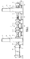
- the tube 1 of modular length is formed from several tubular elements 1a, 1b, 1c ..., independent and fixed end to end by means of connection flanges 4 fixed to each other for example by bolts 5.
- a seal is arranged at the interface of the tubular elements 1a, 1b, 1c ... associated.
- injection means 10 are constituted by a pressure supply tank 11 containing the product to be sterilized and fixed on a base 12.
- the injection means 10 also comprise a filling slide valve 13 formed by a rectangular section plate comprising, at its lower part, a transverse orifice 14 and, at its upper part, a channel 15 for circulation of the communicating product to be sterilized with the supply tank 11 under pressure by a telescopic hose 16.
- the filling valve 13 can be moved vertically by a control member between a first position placing the transverse orifice 14 in communication with the chamber 2 and a second position placing the circulation channel 15 in communication with said chamber 2.
- the slide valve 13 is, during its vertical displacement, guided by a part 17 fixed on the end 2a of the tube 1a.
- the part 17 is formed by a vertical plate 17a on which the slide valve 13 slides and by a sheath 17b comprising, on the one hand, a horizontal bore 17c arranged in the axis of the chamber 2 and of diameter corresponding to the diameter of said chamber 2 and, on the other hand, a vertical passage 17d of section corresponding to the section of the slide valve 13 and intended for the sliding of said slide valve 13.
- the movement control member of the slide valve 13 consists of at least one actuator 18 and preferably of two vertical and parallel jacks 18, supported by the base 12.
- the rod 18a of each jack 18 is integral with a base 19 fixed to the upper part of said slide valve 13.
- the device also includes means for sterilizing the first end 2a of the treatment chamber 2 which are shown in FIG. 3.
- sterilization means are formed by a channel 25 formed in the piston 51 and opening at the free end of said piston 51.
- the channel 25 is connected by an orifice 26 to steam injection means, not shown, of so as to sterilize the end 2a of the chamber 2, as will be seen later.
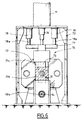
- the means 30 for closing the second end 2b of the treatment chamber 2 comprise a piston 31 of circular section and mounted at the end of a rod 32 of a jack 33.
- the piston 31 can be moved horizontally between a first position in which the free end of said piston 31 is placed in the treatment chamber 2 and a second position in which said free end of the piston 31 is located outside said chamber 2.
- the piston 31 is associated with means for locking said piston 31 in the closed position of the chamber 2, which consist of two opposite jaws 34 and each controlled by a jack 35.
- the jaws 34 can be moved vertically between a locking position of the piston 31 as shown in FIG. 5 and an unlocking position releasing said piston 31.
- the means 50 for compressing the product in the treatment chamber 2 consist of a piston 51 of circular section and of diameter corresponding to the diameter of the treatment chamber 2.
- the piston 51 is fixed to the free end of a rod 52 comprising at its end opposite to that on which the piston 51 is fixed, a control piston 53 of a jack 54.
- the jack 54 comprises conduits 55 and 56 for supplying pressurized fluid.
- the piston 51 is horizontally movable in the axis of the treatment chamber 2 between a first position in which the free end of this piston 51 is introduced into the treatment chamber 2 passing through the transverse orifice 14 of the valve to drawer 13, as shown in FIG. 2 and a second position in which the free end of said piston 51 is retracted and positioned outside the chamber 2 and the horizontal bore 14 of the slide valve 13.
- the means 70 for recovering the sterilized product are formed by a reservoir 71 for sterile recovery, supported by a base 72.
- the recovery means 70 also comprise a drain valve 73 formed by a plate of rectangular cross section comprising, at its lower part, a transverse orifice 74 for the passage of the closure piston 31 and, at its upper part, a channel circulation 75 communicating with the recovery tank 71 by a telescopic pipe 76.
- the slide valve 73 for recovery is movable vertically by a control member between a first position bringing the transverse orifice 74 into communication with the chamber 2 and a second position bringing the circulation channel 75 into communication with said chamber 2.
- the slide valve 73 is, during its vertical displacement, guided by a part 77 fixed on the end 2b of the tube 1c.
- the part 77 is formed by a vertical plate 77a on which the slide valve 73 slides and by a sheath 77b comprising a horizontal bore 77c disposed in the axis of the treatment chamber 2 and a vertical passage 77d of section corresponding to the section of the slide valve 73 and intended to allow the vertical sliding of the slide valve 73 between the two positions.
- the member for controlling the movement of the slide valve 73 consists of at least one actuator 78 and preferably two vertical cylinders 78, supported by the base 72.
- each jack 78 is integral with a base 79 fixed to the upper part of said slide valve 73.
- the sheath 77b of the piece 77 serves as a member for guiding the piston 31 and for supporting the jack 33 and the two jacks 35 for controlling the jaws 34.
- the sterilization device as described above makes it possible to sterilize successive volumes of product and comprises, for this purpose, means 3 for separating the volume of the sterilized product with the volume of the product to be sterilized.
- These separation means are formed by several independent cylindrical separators of diameter corresponding to the diameter of chamber 2 and comprising sealing members with the wall of said chamber 2.
- These cylindrical separators 3 are intended to be moved from the end 2a to the end 2b of the treatment chamber 2 between each volume of product and to be recycled from the second end 2b to the first end 2a of said treatment chamber 2 .
- the device comprises means 90 for transferring the cylindrical separators 3 from one end to the other of the chamber 2.
- the means 90 for transferring the cylindrical separators are formed by a return pipe 91 disposed below the tube 1 and extending over the entire length of said tube 1.
- the return pipe 91 has at its end 91a located below the end 2b of the tube 2, an airlock 92 connected to said end 2b of the tube 1 by the drain valve 73.
- the device comprises means for sterilizing the airlock 92 for recovering the separators 3. These means are formed by an orifice 85 formed in a wall of said airlock 92 and connected to steam injection means, not shown.
- the drain valve 73 is pressed against the vertical plate 77a so as to seal the circulation channel 75.
- the base 72 supports a jack 86 comprising a rod 87 whose free end is provided with a plate 88 intended to come to bear on the slide valve 73 to apply said slide valve 73 on the vertical plate 77a during the sterilization of the airlock 92.
- the bottom of the airlock 92 is equipped with an orifice 89 for evacuating dirt during the sterilization of the airlock 92.
- the pipe 91 also comprises at its end 91a, a member 93 for introducing the cylindrical separators 3 into the return pipe 91, means 98 for propelling the cylindrical separators 3 into the return pipe 91 and means 99 for cleaning said separators cylindrical 3.
- the member 93 for introducing the cylindrical separators 3 into the return pipe 91 is formed by a piston 94 fixed to the free end of a rod 95 of a jack 96.
- the piston 94 is horizontally movable between a first position in which its free end penetrates into the return pipe 91 by passing through the airlock 92 and a second position in which said free end of the piston 94 is located outside the airlock 92.
- the means 98 for propelling the cylindrical separators 3 in the return pipe 91 are formed by a channel 98a which traverses over its entire length the piston 94 and which opens at the free end of said piston 94.
- This conduit 98a is connected to a supply source, not shown, of a pressurized fluid.
- the cleaning means 99 comprise a sleeve 100 disposed around the end 91a and which determines a chamber 101 in which the return pipe 91 is pierced with a multitude of small orifices 102.
- the chamber 101 is connected by a conduit 103 to means, not shown, for supplying a fluid for cleaning and sterilizing the cylindrical separators 3.
- the end 91b of the return pipe 91 located below the end 2a of the chamber 2 of the tube 1 comprises an airlock 110 for recovering the cylindrical separators 3 and which communicates with the end 2a of the chamber 2 by the valve with slide 13 for the transfer of said cylindrical separators from the return pipe 91 into the treatment chamber 2.
- the airlock 110 also serves as a water recovery chamber during the injection of water vapor at the end 2a of the chamber 2.
- the supply slide valve 13 is in the high position so that the transverse orifice 14 in which a cylindrical separator 3 has been placed, is positioned in alignment of chamber 2.
- the recovery slide valve 73 is also in the high position and the end 2b of chamber 2 is closed by the piston 31 which passes through the transverse orifice 74 of said slide valve 73.
- a second cylindrical separator 3 is waiting in the end 91a of the return pipe 91.
- the piston 51 of the jack 54 is moved to introduce the first cylindrical separator 3 into the treatment chamber 2.
- a first volume V1 of product to be sterilized is injected into the chamber 2 which displaces the first cylindrical separator 3 up to the piston 31.
- the pressurized fluid is injected into the return pipe 91 through the conduit 98a of the piston 94 which has the effect of displacing the second cylindrical separator 3 in this return pipe 91 and placing said second cylindrical separator 3 in the transverse orifice 14 of the slide valve 13.
- the compression piston 51 is brought back outside of the treatment chamber 2, the filling slide valve 13 is placed in the low position so as to put the reservoir 11 back into communication with this treatment 2 by the telescopic pipe 16 and the supply channel 15, then the closure piston 31 is brought back outside the treatment chamber 2 as shown in FIG. 7F.
- the water is collected in the airlock 110.
- This sterilization is carried out between each injection of the product to be sterilized and the injection of water vapor is maintained for the time necessary in order to obtain adequate sterilization.
- the recovery slide valve 73 is placed in the low position to put the treatment chamber 2 in communication with the sterile recovery tank 71 and position the first cylindrical separator 3 in alignment with the return pipe 91, as shown on the Fig. 7G.
- a second volume V2 of the product to be treated is injected into the treatment chamber 2 from the supply tank 11 thus causing the transfer of the first volume V1 of the sterilized product into the recovery tank 71 and the displacement from the second cylindrical separator 3 to the end 2b of the treatment chamber 2.
- water vapor is injected through the orifice 85 to sterilize the airlock 92 and recover the dirt through the orifice 89.
- the jack 86 is actuated so that, under the effect of the thrust exerted by the rod 87, the plate 88 comes to bear on the slide valve 73.
- the piston 94 is moved horizontally to transfer the second cylindrical separator 3 from the airlock 92 to the cleaning chamber 101 into which a cleaning and sterilization fluid is injected.
- the pressurized fluid is injected through the conduit 98a of the piston 94 to move this second cylindrical separator 3 in the return pipe 91 and place it on standby in the transverse orifice 14 of the slide valve 13.
- Each volume of the product is compressed at a pressure of between 5000 and 8000 bars.
- the high-pressure sterilization device makes it possible to sterilize large volumes of product, such as for example liquid or solid products, while presenting all the guarantees of safety. essential for use very high pressure.
- the sterilization process and device according to the invention allow the sterilized product to retain these original qualities, for example its taste and appearance.
Landscapes
- Life Sciences & Earth Sciences (AREA)
- Engineering & Computer Science (AREA)
- Wood Science & Technology (AREA)
- Zoology (AREA)
- Chemical & Material Sciences (AREA)
- Food Science & Technology (AREA)
- Polymers & Plastics (AREA)
- Health & Medical Sciences (AREA)
- Epidemiology (AREA)
- Animal Behavior & Ethology (AREA)
- General Health & Medical Sciences (AREA)
- Public Health (AREA)
- Veterinary Medicine (AREA)
- Food Preservation Except Freezing, Refrigeration, And Drying (AREA)
- Apparatus For Disinfection Or Sterilisation (AREA)
Applications Claiming Priority (2)
| Application Number | Priority Date | Filing Date | Title |
|---|---|---|---|
| FR9501730 | 1995-02-15 | ||
| FR9501730A FR2730412B1 (fr) | 1995-02-15 | 1995-02-15 | Procede et dispositif de sterilisation a haute pression de produits |
Publications (1)
| Publication Number | Publication Date |
|---|---|
| EP0727227A1 true EP0727227A1 (de) | 1996-08-21 |
Family
ID=9476161
Family Applications (1)
| Application Number | Title | Priority Date | Filing Date |
|---|---|---|---|
| EP96400241A Withdrawn EP0727227A1 (de) | 1995-02-15 | 1996-02-05 | Verfahren und Vorrichtung zum Hochdrucksterilisieren von Produkten |
Country Status (6)
| Country | Link |
|---|---|
| US (2) | US5788934A (de) |
| EP (1) | EP0727227A1 (de) |
| JP (1) | JPH08238303A (de) |
| FR (1) | FR2730412B1 (de) |
| IL (1) | IL117049A (de) |
| ZA (1) | ZA961102B (de) |
Cited By (6)
| Publication number | Priority date | Publication date | Assignee | Title |
|---|---|---|---|---|
| WO1997043914A1 (en) * | 1996-05-17 | 1997-11-27 | Unilever N.V. | Method for preservation under pressure |
| FR2764232A1 (fr) * | 1997-06-10 | 1998-12-11 | Framatome Sa | Procede et dispositif de pressurisation de produits solides ou liquides places dans une enveloppe etanche |
| FR2764233A1 (fr) * | 1997-06-10 | 1998-12-11 | Framatome Sa | Procede et dispositif de pressurisation de produits liquides ou solides |
| EP0894440A1 (de) * | 1997-08-01 | 1999-02-03 | The Coca-Cola Company | Verfahren und Vorrichtung zum Hochdruck Sterilisation |
| US6635223B2 (en) | 2000-10-25 | 2003-10-21 | Andreas Maerz | Method for inactivating micro-organisms using high pressure processing |
| AT517951B1 (de) * | 2016-01-14 | 2017-06-15 | Peter Arbeiter | Vorrichtung zum Abtöten von Keimen und/oder Krankheitserregern |
Families Citing this family (11)
| Publication number | Priority date | Publication date | Assignee | Title |
|---|---|---|---|---|
| CA2270255A1 (en) * | 1996-10-29 | 1998-05-07 | Unilever Plc | Method for the preparation of a foodstuff |
| FR2781413A1 (fr) * | 1998-07-27 | 2000-01-28 | Clextral | Dispositif d'etancheite d'une chambre de traitement d'une installation de pressurisation de produits solides ou liquides |
| EP1180945A1 (de) * | 1999-05-28 | 2002-02-27 | Universite Laval | Verfahren zur inaktivierung der lebensmittelverderblichkeit und pathogener mikroorganismen durch dynamischen hochdruck |
| WO2001094102A1 (en) * | 2000-06-07 | 2001-12-13 | Sig Simonazzi S.P.A. | A material with a high degree of impermeability to gases and a method for the production thereof |
| CA2462556A1 (en) * | 2001-10-23 | 2003-05-01 | Sig Simonazzi S.P.A. | Pressurization device |
| US20050249614A1 (en) * | 2004-05-06 | 2005-11-10 | Sukhoi Naphtha Corporation | Pump for evacuation of viscous liquids |
| GB2423310A (en) * | 2005-02-22 | 2006-08-23 | Arch Timber Protection Ltd | Method of generating a pressure differential |
| US20090232959A1 (en) * | 2008-03-13 | 2009-09-17 | Cargill, Incorporated | High pressure meat product processing |
| US12175546B2 (en) | 2016-06-17 | 2024-12-24 | Chipotle Mexican Grill, Inc. | Make line optimization |
| CN111328911B (zh) * | 2020-03-05 | 2023-06-20 | 米开朗食品股份有限公司 | 一种高压低温消毒的工艺及其装置 |
| CN113134496A (zh) * | 2021-04-29 | 2021-07-20 | 哈动国家水力发电设备工程技术研究中心有限公司 | 一种抽水蓄能机组管路微生物附着清除方法 |
Citations (5)
| Publication number | Priority date | Publication date | Assignee | Title |
|---|---|---|---|---|
| FR2690854A1 (fr) * | 1992-05-05 | 1993-11-12 | Acb | Installation pour le traitement à très haute pression de produits liquides. |
| US5288462A (en) * | 1992-05-18 | 1994-02-22 | Stephen D. Carter | Sterilization apparatus and method |
| US5316745A (en) * | 1993-01-28 | 1994-05-31 | Flow International Corporation | High pressure sterilization apparatus and method |
| EP0623353A1 (de) * | 1993-05-07 | 1994-11-09 | Framatome | Vorrichtung zum Hochdrucksterilisieren von Produkten |
| WO1994028745A1 (en) * | 1993-06-11 | 1994-12-22 | Asea Brown Boveri Ab | Device for high-pressure treatment of substances |
Family Cites Families (2)
| Publication number | Priority date | Publication date | Assignee | Title |
|---|---|---|---|---|
| US2069820A (en) * | 1932-07-13 | 1937-02-09 | Adiel Y Dodge | Sterilizing process |
| JP2622315B2 (ja) * | 1991-04-17 | 1997-06-18 | 三菱重工業株式会社 | 連続加圧装置 |
-
1995
- 1995-02-15 FR FR9501730A patent/FR2730412B1/fr not_active Expired - Fee Related
-
1996
- 1996-02-05 EP EP96400241A patent/EP0727227A1/de not_active Withdrawn
- 1996-02-06 IL IL11704996A patent/IL117049A/xx active IP Right Grant
- 1996-02-12 ZA ZA961102A patent/ZA961102B/xx unknown
- 1996-02-12 US US08/600,210 patent/US5788934A/en not_active Expired - Fee Related
- 1996-02-13 JP JP8025489A patent/JPH08238303A/ja not_active Withdrawn
-
1997
- 1997-12-19 US US08/994,320 patent/US5948356A/en not_active Expired - Fee Related
Patent Citations (5)
| Publication number | Priority date | Publication date | Assignee | Title |
|---|---|---|---|---|
| FR2690854A1 (fr) * | 1992-05-05 | 1993-11-12 | Acb | Installation pour le traitement à très haute pression de produits liquides. |
| US5288462A (en) * | 1992-05-18 | 1994-02-22 | Stephen D. Carter | Sterilization apparatus and method |
| US5316745A (en) * | 1993-01-28 | 1994-05-31 | Flow International Corporation | High pressure sterilization apparatus and method |
| EP0623353A1 (de) * | 1993-05-07 | 1994-11-09 | Framatome | Vorrichtung zum Hochdrucksterilisieren von Produkten |
| WO1994028745A1 (en) * | 1993-06-11 | 1994-12-22 | Asea Brown Boveri Ab | Device for high-pressure treatment of substances |
Cited By (12)
| Publication number | Priority date | Publication date | Assignee | Title |
|---|---|---|---|---|
| WO1997043914A1 (en) * | 1996-05-17 | 1997-11-27 | Unilever N.V. | Method for preservation under pressure |
| US6033717A (en) * | 1996-05-17 | 2000-03-07 | Unilever Patent Holdings | Method for preservation under pressure |
| FR2764232A1 (fr) * | 1997-06-10 | 1998-12-11 | Framatome Sa | Procede et dispositif de pressurisation de produits solides ou liquides places dans une enveloppe etanche |
| FR2764233A1 (fr) * | 1997-06-10 | 1998-12-11 | Framatome Sa | Procede et dispositif de pressurisation de produits liquides ou solides |
| WO1998056265A1 (fr) * | 1997-06-10 | 1998-12-17 | Clextral | Procede et dispositif de pressurisation de produits solides ou liquides places dans une enveloppe etanche |
| WO1998056264A1 (fr) * | 1997-06-10 | 1998-12-17 | Clextral | Procede et dispositif de pressurisation de produits liquides ou solides |
| EP0894440A1 (de) * | 1997-08-01 | 1999-02-03 | The Coca-Cola Company | Verfahren und Vorrichtung zum Hochdruck Sterilisation |
| US6004508A (en) * | 1997-08-01 | 1999-12-21 | The Coca-Cola Company | Method and apparatus for super critical treatment of liquids |
| US6162392A (en) * | 1997-08-01 | 2000-12-19 | The Coca-Cola Company | Method and apparatus for super critical treatment of liquids |
| US6635223B2 (en) | 2000-10-25 | 2003-10-21 | Andreas Maerz | Method for inactivating micro-organisms using high pressure processing |
| AT517951B1 (de) * | 2016-01-14 | 2017-06-15 | Peter Arbeiter | Vorrichtung zum Abtöten von Keimen und/oder Krankheitserregern |
| AT517951A4 (de) * | 2016-01-14 | 2017-06-15 | Peter Arbeiter | Vorrichtung zum Abtöten von Keimen und/oder Krankheitserregern |
Also Published As
| Publication number | Publication date |
|---|---|
| FR2730412B1 (fr) | 1997-04-30 |
| IL117049A0 (en) | 1996-06-18 |
| ZA961102B (en) | 1997-08-12 |
| US5788934A (en) | 1998-08-04 |
| IL117049A (en) | 1999-07-14 |
| JPH08238303A (ja) | 1996-09-17 |
| FR2730412A1 (fr) | 1996-08-14 |
| US5948356A (en) | 1999-09-07 |
Similar Documents
| Publication | Publication Date | Title |
|---|---|---|
| EP0727227A1 (de) | Verfahren und Vorrichtung zum Hochdrucksterilisieren von Produkten | |
| FR2470321A1 (fr) | Vanne | |
| FR2529673A1 (fr) | Procede et appareil pour effectuer un essai de pression hydraulique sur un tube | |
| CH351074A (fr) | Procédé de fabrication et de remplissage d'un récipient en matière plastique et installation pour sa mise en oeuvre | |
| EP0496652A1 (de) | Verfahren und Vorrichtung zur Entnahme und Konditionierung von Proben unterirdischen Wassers, insbesondere zur Bestimmung von gelösten Gasen, sowie ihre Verwendung bei einer bakteriellen Analyse | |
| EP0772981B1 (de) | Isostatische Presse für Hochdruckbehandlung von Schüttgut, insbesondere von mit Partikeln beladenen flüssigen Lebensmitteln | |
| CA2358549C (fr) | Procede de refoulement dans une machine de remplissage et machine de remplissage pour la mise en oeuvre d'un tel procede | |
| CH370914A (fr) | Procédé pour la distribution de matières granuleuses et dispositif pour la mise en oeuvre de ce procédé | |
| FR2686830A1 (fr) | Presse pour comprimer des futs de dechets contamines. | |
| EP0487161B1 (de) | Verfahren zum Abfüllen nicht mischbarer Flüssigkeiten in Fässer und dessen Anwendungen, insbesondere für die Abfüllung von weissem Phosphor | |
| FR2764233A1 (fr) | Procede et dispositif de pressurisation de produits liquides ou solides | |
| FR2810634A1 (fr) | Dispositif de dosage pour produits liquides ou pateux | |
| FR2788509A1 (fr) | Dispositif de remplissage volumetrique | |
| FR2528450A1 (fr) | Procede et dispositif pour incorporer une dose de liqueur dans une bouteille de vin champagnise | |
| EP0457682A1 (de) | Verfahren zur Beseitigung von Verstopfungen in einer Rohrleitung für den Transport von gefährlichen Stoffen | |
| FR2764232A1 (fr) | Procede et dispositif de pressurisation de produits solides ou liquides places dans une enveloppe etanche | |
| FR2720193A1 (fr) | Procédé d'introduction d'un électrolyte dans un carter d'élément accumulateur et installation pour sa mise en Óoeuvre. | |
| EP0287622A1 (de) | Abfüllanlage | |
| FR2573177A1 (fr) | Dispositif de distribution d'un liquide cryogenique | |
| EP0238412B1 (de) | Verfahren und Vorrichtung zum Ausführen von Arbeiten an einem im Betrieb befindlichen Gasrohr | |
| FR2683809A1 (fr) | Tete de connexion pour installation de lavage-remplissage de recipients de stockage temporaire de produit liquide et installation en faisant application. | |
| FR2878312A1 (fr) | Procede de remplissage d'un recipient de fluide sous pression a entree et sortie separees | |
| FR2676187A1 (fr) | Dispositif et procede de lavage d'une cuve de conservation de lait. | |
| CH349818A (fr) | Machine d'essai pour la détermination de la résistance des parois d'un tube au moyen d'un fluide sous pression | |
| WO2020099543A1 (fr) | Dispositif de tireuse pour machine de remplissage et machine comportant de tels dispositifs |
Legal Events
| Date | Code | Title | Description |
|---|---|---|---|
| PUAI | Public reference made under article 153(3) epc to a published international application that has entered the european phase |
Free format text: ORIGINAL CODE: 0009012 |
|
| AK | Designated contracting states |
Kind code of ref document: A1 Designated state(s): BE CH DK ES GB GR IT LI MC NL PT SE |
|
| 17P | Request for examination filed |
Effective date: 19970211 |
|
| STAA | Information on the status of an ep patent application or granted ep patent |
Free format text: STATUS: THE APPLICATION HAS BEEN WITHDRAWN |
|
| 18W | Application withdrawn |
Withdrawal date: 19991104 |