EP0727250A2 - Verfahren und Vorrichtung zur Füllung von Behältern mit Teilchen - Google Patents
Verfahren und Vorrichtung zur Füllung von Behältern mit Teilchen Download PDFInfo
- Publication number
- EP0727250A2 EP0727250A2 EP96102369A EP96102369A EP0727250A2 EP 0727250 A2 EP0727250 A2 EP 0727250A2 EP 96102369 A EP96102369 A EP 96102369A EP 96102369 A EP96102369 A EP 96102369A EP 0727250 A2 EP0727250 A2 EP 0727250A2
- Authority
- EP
- European Patent Office
- Prior art keywords
- particles
- particle
- packed
- disc
- laser
- Prior art date
- Legal status (The legal status is an assumption and is not a legal conclusion. Google has not performed a legal analysis and makes no representation as to the accuracy of the status listed.)
- Granted
Links
Images











Classifications
-
- B—PERFORMING OPERATIONS; TRANSPORTING
- B01—PHYSICAL OR CHEMICAL PROCESSES OR APPARATUS IN GENERAL
- B01J—CHEMICAL OR PHYSICAL PROCESSES, e.g. CATALYSIS OR COLLOID CHEMISTRY; THEIR RELEVANT APPARATUS
- B01J8/00—Chemical or physical processes in general, conducted in the presence of fluids and solid particles; Apparatus for such processes
- B01J8/0015—Feeding of the particles in the reactor; Evacuation of the particles out of the reactor
- B01J8/003—Feeding of the particles in the reactor; Evacuation of the particles out of the reactor in a downward flow
-
- G—PHYSICS
- G05—CONTROLLING; REGULATING
- G05D—SYSTEMS FOR CONTROLLING OR REGULATING NON-ELECTRIC VARIABLES
- G05D9/00—Level control, e.g. controlling quantity of material stored in vessel
- G05D9/12—Level control, e.g. controlling quantity of material stored in vessel characterised by the use of electric means
Definitions
- This invention relates to a method of packing particles, such as of catalysts, grains, or feedstuff, into reaction vessels, silos, or the like by means of a packing apparatus comprising a particle distributor (loading machine) and a packing monitor so as to obtain a flat, smooth packed surface and also relates to a distribution and packing apparatus to be used for the method. More particularly, this invention concerns a method of packing a catalyst into any of various reaction vessels typified by oil refining equipment, to obtain a smooth packed surface while monitoring in real time the unevenness of the catalyst deposit surface and also concerns a catalyst distribution and packing system capable of realizing a flat catalyst packed surface, easy and simple control, convenient handling and installation, and high speed catalyst conveyance without damaging or breaking the catalyst particles.
- Catalysts are utilized, for example, in the synthesis or decomposition of various materials.
- catalysts are often used in the oil industry, in refining heavy cycle oil to high-octane gasoline or in simultaneous desulfurization and cracking in the presence of a large quantity of hydrogen.
- the catalysts for use in catalytic cracking are, e.g., solid acid silica, alumina, and zeolite catalysts.
- These catalysts are packed in reaction vessels (packed towers). Since the packed catalyst condition governs the efficiency of operation, it is customary to mount a catalyst distributor in the upper, central space of the reaction vessel and scatter the falling catalyst particles in the space accomplish uniform packing.
- the packed particle surface usually undulates. If the undulation exceeds a predetermined level, the operation efficiency drops. To avoid this, the unevenness must be corrected somehow or other, for example by controlling a scatter parameter of the packing apparatus. It is important especially with a catalyst to idealize the space presence density and control the packing velocity within the range of dense loading on the packed surface (high density packing of catalyst particles with the axial directions of the particles aligned in the horizontal plane).
- the unevenness of the packed surface of scattered particles is not easy to determine because of the depth of reaction vessels; it has usually been determined by manual measurement of suitably chosen measuring points with a measuring tape unwound from the level of the packing apparatus.
- the measurement is made, e.g., at intervals of once in 30 minutes at 12 measuring points. This is time-consuming and just a rule of thumb. In extreme cases the accuracy of measurement is as poor as ⁇ 50 mm and the packed surface distribution is as large as 400 mm. The efficiency of packing operation is low because the operation is interrupted whenever the measurement is made.
- This system is a packing monitoring method for use when a vessel is packed with particles, characterized by scanning the packed surface with laser light, detecting the reflected light, and measure the deposit height by trigonometry from the position of specific scanned points, laser light emitting position, and laser light detecting position.
- the method uses a packing monitor system comprising a laser light generating and scanning unit which generates a laser light having a beam diameter larger than the cross sectional area of the particles and chosen depending on the target accuracy to scan the packed particle surface with the laser light, and an imaging unit for detecting the reflected laser light from the scanned points, both of the units being mounted inside the vessel to be packed with the particles and at levels above the packed height, a computer for computing the depths of scanned points by trigonometry from the positions of specific scanning points, the position of the laser light generating and scanning unit, and the position of the imaging unit, and a displaying the data including the packed surface depth distribution.
- the particle packing monitoring method that utilizes laser beam scanning has made it possible to monitor and measure the deposited surface condition in real time and more properly than heretofore. In actual observation, however, the method leaves room for improvement in processing abundant data within a short time while maintaining good accuracy and in distinguishing between deposited particles and the particles being scattered.
- particle distributors have heretofore been used.
- One example is a type which has side slits equipped with adjustable gates and lower slits at the bottom and includes a rotating disc attached to the bottom, so that the distribution state can be controlled by adjusting the openings of the side and lower slits and the number of revolution of the rotating disc.
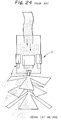
- FIGs. 24, 25, and 26 Other examples of existing particle (catalyst) distributors include “Densi Cat”, “UOP”, and “COP” types shown, respectively, in FIGs. 24, 25, and 26. All of them are equipped with a hopper and blades for catalyst scattering.
- the "Densi Cat” type uses a plurality of rubber blades to perform all-directional uniform distribution based on the reflection with the openings of the blades and the scattering by blades.
- the “UOP” type takes advantage of the centrifugal force produced by 2 to 4 straight blades.
- the "COP” type uses 1 to 3 layer blades of elliptical plates provided with guides to cause distribution of scatter distances.
- Japanese Patent Application Publication No. 22807/1989 discloses a method of packing catalyst particles gradually in a reaction vessel by a catalyst discharger liftably hung inside the vessel and moved upward so as to maintain the distance between the discharger and the packed particle surface within a preset range.
- the catalyst packing apparatus described for use in the method comprised a platform suspended inside the vessel and a catalyst discharger mounted on the platform, the discharger comprising a motor and a saucer rotatably driven by the motor, the saucer having vertical weirs formed at predetermined intervals and slits formed between the weirs.
- the particle packing monitoring method that utilizes laser beam scanning has made it possible to monitor and measure the deposited surface condition in real time and more accurately than heretofore. In actual observation, however, the method leaves room for improvement in processing plentiful data within a short time while maintaining good accuracy and in distinguishing between deposited particles and the particles being scattered. It is another object of the present invention to establish a procedure for handling the data by image processing.
- a packed particle surface can be simply smoothed in a particle packing apparatus which comprises a packing monitor and a particle distributor (loading machine) capable of forming a concave-conical packed surface when scattering the particles in a steady state and having a parameter with which to control the size of the zone, by gradually decreasing the size of the resulting cone.
- a particle packing apparatus which comprises a packing monitor and a particle distributor (loading machine) capable of forming a concave-conical packed surface when scattering the particles in a steady state and having a parameter with which to control the size of the zone, by gradually decreasing the size of the resulting cone.
- this invention provides a method of smoothing the particle packed surface with a particle packing apparatus which includes a particle distributor (loading machine) capable of forming a concave-conical packed surface upon scattering of particles in a steady state and having a parameter with which to control the size of the cone and a packing monitor capable of continuously grasping the entire packed surface condition, characterized by forming a concave-conical packed surface of the particles scattered in a steady state by the distributor while the packing monitor is continuously grasping the formation of the packed surface, and intermittently or continuously controlling the parameter of the particle distributor to reduce the cone size gradually and form and deposit, on the inner side of the concave-conical packed surface, successively smaller packed surfaces at predeterminedintervals or uninterruptedly, whereby a flat, smooth packed surface is formed.
- a particle distributor loading machine
- the operation of smoothening the packed particle surface may be repeatedly made.
- This invention also provides a method of flattening the particle packed surface characterized in that when a concave-conical packed surface formed by scattering the particles in a steady state for a given time period has a height at the center (h(ct)) and the height at the edge or periphery (h(edge)), the profile of the concave-conical packed surface to be formed by scattering the particles by controlling the parameters of a particle packing apparatus is made as 2 ⁇ h(edge)/h(ct) ⁇ 1 .
- This invention further provides a method of flattening the particle packed surface characterized by using a particle packing apparatus by which the profile of a concave-conical packed surface formed by scattering the particles in a given state for a given time period has a height at the center (h(ct)) and the height at the edge or periphery (h(edge)), the profile is made as 2 ⁇ h(edge)/h(ct) ⁇ 1 .
- a useful example of particles is catalyst particles.
- the distributor (loading machine) to be used may be of any type that can produce a concave-conical packed surface upon distribution in a steady condition, with a parameter whereby the size of the cone is controlled.
- a distributor that can form a concave-conical packed surface when particles are scattered inside a vessel under condition such that the maximum scatter distance reaches the inner wall of the vessel, the distributor having a parameter with which to control the size of the cone.
- a suitable example of such a distributor are the type having side slits equipped with adjustable, for example pneumatically, gates, one for each, and a low slit at the bottom, and a rotating disc attached to the bottom, the openings of the side and lower slits and the number of revolution of the rotating disc being adjustable to control the scatter condition.
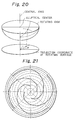
- Another suitable example is the type comprising an outside cover, a hopper located inside and supported by the cover, with the lower end open, a motor mounted on the hopper and couple to a rotating shaft extending downwardly through the center of the hopper and beyond the lower opening thereof, and a uniaxial spheroidal rotating disc fixed to the lower end of the motor rotating shaft so as to receive the particles falling from the hopper, said rotating disc having slits formed to discharge particles therefrom, each said slit being so shaped that the path of particles therethrough is a locus represented by the sum of a locus of a particle that has fallen from the hopper onto the center of the uniaxial spheroidal disc moves until its movement reaches the speed of the disc under the action of the rotational force and the function of the locus in which the angle of retardation in the rotating direction with respect to the distance of radial movement from the center of the disc agrees with the required quantity of particles to be scattered in the radial position.
- the slitted disc of the saucer type used in the above-mentioned Patent Application Publication No. 22807/1989 is very shallow and small in diameter. It receives catalyst particles falling down from a chute, release the particles by centrifugal force sideways toward the periphery of the saucer while, at the same time dropping the particles evenly through slits.
- the slits are merely formed straightly in the radial direction, and weirs formed therebetween rather hamper free flow of the catalyst particles.
- the distributor of this reference is fundamentally different in concept from that of this invention that discharges particles through curved slits formed in the bottom of a uniaxial spheroidal disc so as to match the motion of the particles on the disc.
- the packing monitor may be of any type capable of continuously watching and observing the entire packed surface, such as a television type monitoring device.
- Preferred for the purposes of the invention is a type comprising a laser-scanner for producing a laser beam having a beam diameter greater than the cross sectional area of the particles and chosen depending on the target accuracy to scan the deposited particle surface, an imaging device for detecting laser reflection light from scanned points, said laser-scanner and imaging device being both attached to the inner wall of the vessel at levels above the packed height therein, a computer for calculating the depth of packed surface at specific scanned points by trigonometry from the locations of the scanning points at the time of measurement, the position of the laser-scanner, and the position of the imaging device, and a display device that displays the data including the packed surface distribution.
- the falling particles pass across the path of laser light being directed to points on matrices of the deposit surface, making the laser spot on the deposit surface scarcely discernible. In each frame usually a large number of particles falling across the laser light path glitter. Integration of images in several frames changes the luminant spots of scattering particles into a continuous line.
- the selection in advance of an image closest to one of the laser spot images registered renders it possible to distinguish between the laser spot incident on the deposit surface and the luminant spots with the scattering particles in the light path. Then the center of gravity of the preselected image is found and is used as a coordinate of the laser spot. To shorten the time required for image processing, only a certain area around the point which is expected to meet the laser spot is subjected to image processing. It is only necessary to perform image processing of a range from that point of at least one half of the maximum value of unevenness (in the depth direction) of the deposit surface, i.e., a square-shaped range in which each side is equivalent to at least the maximum value of unevenness (in the depth direction) of the deposit surface.
- the invention provides a method of monitoring particle packing which comprises, in packing particles in a vessel, scanning the deposit surface with laser light, detecting the reflected light, and measuring the deposit height by trigonometry from locations of specific scanned points, laser light emitting position, and laser light detecting points, characterized by the steps of dividing the deposit surface into matrices of m x n, sequentially irradiating the points on the matrices with laser, and performing image processing whereby several frames of images taken at each point are integrated to choose an image closest to a laser spot registered beforehand, and the center of gravity of each said image is found and made a laser spot, said image processing being made only within a range of at least one half of the maximum value of unevenness (in the depth direction) of the deposit surface from the points expected to meet the laser spot.
- the scanning range of a deposit surface is divided into m x n matrices, and points on the matrices are sequentially irradiated with laser light to scan the deposited particle surface.
- Several frames of laser image are taken by a camera from each point.
- the images of several frames each are integrated, and an image closest to a preregistered laser spot image is selected.
- the center of gravity of the image is found and used as a laser spot.
- Recognition of deposited particles with good accuracy is done by image processing. To shorten the time required for the image processing, only a certain range from the point that is expected to meet the laser spot is image processed.
- High accuracy recognition of deposited particles is made possible by image processing of a range of at least one half of the maximum value of deposited surface unevenness (in the depth direction), or a square range each side of which is more than the maximum value of the deposited surface unevenness (in the depth direction).
- FIG. 1(a) shows a packing apparatus 2 comprising a distributor (loading machine) 3 held in the upper center of the reactor 1 to scatter and pack catalyst particles C into the space and a packing monitor 4 for continuously monitoring the condition of the packed surface S of catalyst particles being deposited.
- the distributor 3 to be used may be of any type that can produce a concave-conical packed surface upon distribution in a steady condition, with a parameter (e.g., number of revolution) whereby the size of the cone is controlled.
- a distributor that can form a concave-conical packed surface and has a parameter to control the size of the cone where the catalyst particles are scattered inside the reaction vessel 1 under condition such that the maximum scatter distance reaches the inner wall of the vessel.
- the packing monitor 4 may be of any type that can continuously watch and observe the entire packed surface S.
- FIG. 5 shows a typical distributor 3.
- FIG. 5 (a) is a side view
- FIG. 5 (b) shows a bottom slit.
- the distributor has four side slits 21 formed in the side wall and one lower slit 23 at the bottom as shown at (b).
- a rotating disc 24 is suspended from the bottom.
- Each side slit is equipped with a adjustable gate 25.
- the lower slit also is adjustable. The distribution process can be controlled by adjusting the openings of the side and lower slits and the number of revolution of the rotating disc in response to the latest information on the packed surface.
- the packing monitor 4 which may, for example, be a television monitor, is illustrated as a laser scanning type comprising a laser-scanner 5 and an imaging device 9, both of which are attached to the inner wall of the reaction vessel at substantially the same height as the distributor 3.
- the laser-scanner 5 produces a scanning laser beam 6.
- the imaging device 9 detects laser reflection light within a predetermined field of vision.
- a computer 11 calculates the depth of packed surface at specificscanned points by trigonometry from the location of the scanned points at the time of measurement, the position of the laser generator-scanner, and the position of the imaging device.
- the computer 11 and a CRT 13 that displays the data including the packed surface distribution are installed in a monitor chamber at a suitable location outside the reaction vessel.
- FIG. 1(b) is a transverse sectional view of the packed surface S as seen from the level of the distributor 3, laser generator-scanner 5, and imaging device 9. It shows how the packed surface S is scanned with the scanning laser beam 6.
- the packed surface is monitored by the detection of reflected light from scanning points at regular intervals while the scanning laser beam 6 is scanning the packed surface from end to end and from left to right.
- FIG. 2 shows how the laser-scanner 5 and imaging device 9 are attached to the inner wall of the vessel.
- the laser-scanner 5 comprises a laser source 7, e.g., of He-Ne laser or semiconductor laser, and a laser scanner 8 that scans left to right and back and forth.
- the laser beam direction can be changed by gradually changing the inclination of an optical means such as a prism.
- the laser source 7 and the laser scanner 8 are located inside and immediately below a dust cover 17 which in turn is connected to an air line 16. An air stream from the air line 16 constantly flows through the dust cover 17 to keep off the dust.
- the dust cover 17 is secured to the inner wall of the reaction vessel by suitable fittings 18.
- the imaging device 9 typically a CCD camera 10
- the imaging device is located in a dust cover 19 which is connected to an air line 16, and is fixed to the inner wall of the vessel by fittings 20. They are supported on a tray that supports a distributor (not shown) in the center.
- the visual field of the camera depends on the inside diameter of the reaction vessel, the image size of CCD, focal distance of the camera, and the distance from the camerato the packed surface.
- the inside diameter of the reaction vessel 4 m
- CCD image size 1/2 inch type
- a photographic lens of focal distance f 12 mm
- the visual field in the vertical direction of the recovered image is 3 m when the packed surface distance is -10 m and 1.5 m when the packed surface distance is -5 m.
- a plurality of cameras, and sometimes a plurality of laser-scanners may be used instead.
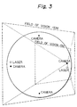
- FIG. 3 shows a four camera-two laser system.
- the fields of vision with -5 m and -10 m are indicated by broken lines.
- the four camera-two laser system which allows a wider spacing between each camera and laser than the three camera-one laser system, permits broader range, higher accuracy measurement.
- the laser beam In the measurement of a packed surface by laser beam scanning, the laser beam must, without fail, reach the packed surface on the bottom of the vessel. The beam must not be interrupted by the catalyst particles that are falling down through the space of the vessel.
- the probability of presence of catalyst particles was calculated. For the calculation, it was assumed that the size of catalyst particles was 1.27 mm in diameter and 3 mm long or 2.12 mm in diameter and 5 mm long, the packing rate was 600 mm/h, and the distance between the measuring point of the vessel to the lowermost layer of the packed surface was 10 m. The results showed that a laser beam with a small diameter was interrupted once in about several seconds.
- the upper limit of laser beam diameter should be determined in consideration of the required measurement accuracy (less than several centimeters) and luminance of the laser scanning points.
- the upper limit usually ranges from 2 to 3 cm for ordinary reaction vessels.
- the upper limit of the laser beam diameter is 3 cm.
- the cross sectional area of catalyst particles is meant the maximum projection area of the (the maximum value of the area of the shadow that is formed upon irradiation of the particles with parallel light).
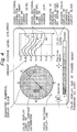
- FIG. 4 is a typical example of basic screen layout of packed surface monitoring. It gives real-time display of the distribution state of the packed surface, a certain selected packed surface section and the like. On the basis of the information of packed surface distribution thus obtained, the condition of scatter from the distributor is modified to keep the distribution of the packed surface constant.
- image processing is recommended so as to process a large quantity of voluminous data within a short time while maintaining the accuracy and distinguish between deposited particles and falling particles.
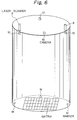
- FIG. 6 shows the absolute coordinate system of cameras 10 and laser positions, image pick-up angles of the cameras 10, angle of swing of the laser scanners 8, and the absolute coordinate system of markers M at three points are input as initialization. Thereafter, the laser spots are aligned with the markers, the marker positions are determined by an image processor, and the mounting directions of the laser scanners and the orientations of the cameras are corrected. From the absolute coordinate system data the scanning range on the bottom surface (deposit surface) is calculated.
- the scanning range is partitioned into matrices of m x n, e.g., 10 x 10, and points on each matrix are sequentially irradiated with a laser, so that the particle deposit surface is scanned with laser light.
- Which point is irradiated with which laser, and which camera is used to obtain which laser image are tabulated beforehand.
- the deposit surface rises gradually, causing changes in the visible fields of the cameras and lasers. Therefore, the table of camera-laser combinations can be changed with the height of the packed surface. For example, 20 different combination tables with heights at an increment of 1 cm may be prepared so as to change the combination table with the gradual rise of the packed height.
- the particles that are scattered and deposited inside a vessel fall down at a mean space density that is dictated by the quantity scattered, size and rate of fall of the particles, capacity of the vessel, etc.
- the exposure time per frame of image varies with the number matrices, scanning time, image processing time, etc., but is usually as short as far less than a fraction of a second. Nevertheless such a large number of particles pass across the laser light path in each frame that they look twinkling.
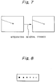
- a frame memory associated with each camera is composed of rows and columns of pixels. Particles coming across the laser light path produce luminant spots, e.g., one at every several pixels. Thus, on integrating the images of several to 10 frames, the luminant spots by a scattering particle are changed into a continuous line as shown in FIG. 7. An image closest to one of the laser spot images registered in advance as in FIG. 8 is selected, the center of gravity of the image is found and is used as a coordinate of the laser spot. To shorten the time required for image processing, only a certain area around the point which is expected from calculation to receive the laser spot is subjected to image processing.
- image processing may be carried out with the above value at the constant level instead of using the maximum value of unevenness of the deposit surface.
- image processing may be limited to the circular range of a radius of about 40 cm to 1 m from the point where laser spotting is anticipated.
- the distance of the point upon which the laser is incident is calculated from the absolute coordinate system of lasers and cameras, the angles of swing of the lasers, and the coordinates of laser spots. This scanning is repeated at all the points of matrices. Upon completion of measurements at all the points, the mean of the measured distances are calculated to be a reference value for the next laser measurement, and the laser irradiation point is calculated again. This is followed by graphic outputting.
- the sequence of image processing steps is represented by a flow chart in FIG. 9.
- a packing apparatus was fixed to the inner wall of a cylindrical vessel of steel about 3 m in diameter and about 18 m high, at a depth of about 5 m from the top of the vessel.
- Columnar ceramic catalyst particles 0.5 to 1.5 mm in diameter and 3 to 5 mm long (with a cross sectional area ranging from 0.0152 to 0.0783 cm 2 ) were scattered in the space at a deposition rate of about one meter per hour.
- the deposit surface was scanned with laser beams, and the unevenness of the deposit surface were measured.
- the laser beam used was a semiconductor laser at 30 mW.
- the laser beam diameter was 10 mm.
- the cameras used were monochromic CCD cameras with a focal distance of 8 mm, 1/2, 380,000 pixels (minimum subject illuminance: 0.2 lux).
- a 512 x 512 pixel image processor was employed.
- laser spot coordinates were found in an increment of 0.1 pixel.
- the exposure time for the cameras was 1/60 second per frame. Only the range at a radius of 40 cm to 1 m from the point calculated to receive the laser spot was image processed.
- a measurement accuracy of ⁇ 17 mm was obtained at a distance of 10 m from the deposit surface and an accuracy of ⁇ 10 mm was obtained at a distance of 5 m.
- the smoothing of packed particle surface involves much difficulties even with the use of such a particle packing apparatus comprising a distributor capable of adjusting a scatter parameter and a packing monitor capable of continuously monitoring the packed surface.
- a particle packing apparatus comprising a distributor capable of adjusting a scatter parameter and a packing monitor capable of continuously monitoring the packed surface.
- the smoothing of packed particle surface can be simply realized by gradually reducing the size of the cone of packed surface that is produced by a particle packing apparatus comprising a particle distributor and a packing monitor, the distributor being capable of forming a concave-conical packed surface upon scattering of particles in a steady state (e.g., in an uncontrolled condition) and having a parameter with which to control the size of the cone.
- the distributor scatters the particles in a steady state and forms a concave-conical packed surface. Thereafter the parameter of the distributor is controlled intermittently or continuously to reduce the size of the cone gradually and deposit smaller packed surfaces inwardly of the preceding packed surface at predetermined intervals or continuously so that the entire packed surface is smoothed.
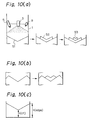
- FIG. 10(a) is a schematic view illustrating the concept of packed surface smoothing or flattening according to this invention. Scattering particles by a distributor in a steady state forms a concave-conical packed surface S1. Next, a second concave-conical packed surface S2 with a smaller cone is formed insidethe first cone, and then a third concave-conical packed surface S3 with a much smaller cone is formed inside the second cone. Although three packed surfaces are shown here, actually a smooth packed surface can easily be formed through finer stepwise or continuous control of scattering. If, for example, an uneven packed surface as shown in FIG. 10(b) is formed, the peripheral portion of the scatter range that is sloped outwardly must be taken into account since it makes smoothing difficult.
- the operation of smoothening the packed particle surface may be repeatedly made.
- the smoothening of the packing of the particles is made while varying the profile of a conical packed surface formed by scattering particles within the range of 2 ⁇ h(edge)/h(ct) ⁇ 1 .
- h(edge)/h(ct) is the ratio of the height at the edge or periphery h(edge) to the height at the center h(ct), when the scattering is continued in a steady state for a given time period, at a certain height of the range over which the particles are packed into the packing vessel as shown in Fig. 10(c).
- the parameter for changing the scatter condition of the particle distributor varies with the distributor type.
- the radius and quantity of distribution can be changed, with the distributor shown in FIG. 5, by adjusting the number of revolution of the rotating disc, with the distributors shown in FIGs. 24 to 26, by adjusting the number of revolution of their rotating blades, and with the distributor shown in FIG. 11, by adjusting the number of revolution of the rotating disc.
- the rotating disc (blade assembly) may be replaced stepwise by those of different diameters.
- the quantity of particle supplied to the rotating disc (blade assembly) may be gradually adjusted.
- Such a parameter is changed for surface smoothing while the powder scatter condition is being watched through the display of the packing monitor. Since in the prior particle scattering apparatus as Fig. 5 and Figs 24 to 26, h(edge)/h(ct) may be widely changed according to the height of the packed surface, it is necessary to change the parameters such as the number of revolution and the quantity of particle supplied according to the height of the packed surface.
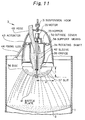
- FIG. 11 a typical distributor (loading machine) to be desirably used in this invention.
- the distributor 3 is provided with anoutside cover 32.
- a hopper 33 is supported by the cover with support means 38.
- the hopper 33 is connected to a stocker (not shown) with a hose 40.
- a rotating shaft 34 extends downwardly through the center of the hopper 33 and projects beyond the lower opening of the hopper. The opening at the lower end of the hopper that surrounds the rotating shaft 34 forms an orifice 39 through which particles are allowed to fall.
- a rotating disc 36 that constitutes about a half of a uniaxial spheroid is fixed, with the head down, to the lower end of the motor rotating shaft 4 so as to receive the particles falling from the hopper.
- the hollow rotating disc is closed except for an opening into which the orifice 39 fits.
- the bottom of the rotating disc 36 has a number of slits 37 to release particles.
- Each slit is so shaped that the path of particles through it is a locus represented by the sum of a locus of a particle that has fallen from the hopper onto the center of the uniaxial spheroidal disc moves until its movement reaches the speed of the disc under the action of the rotational force and the function of the locus in which the angle of retardation in therotating direction with respect to the distance of radial movement from the center of the disc agrees with the required quantity of particles to be scattered in the radial position.
- the orifice diameter is replaceable, and its maximum conductance must be 80% or less than the slit conductance of the rotating disc to prevent the retention of particles on the disc.
- the hopper size is governed by the orifice diameter.
- the motor may be either an electric or air motor, but sufficient torque is a requisite.
- the number of revolution is desirably controlled by the servo system or the like, and the operation is preferably program controllable to effect fine speed changes (inching) during packing and thereby smooth the packed surface. Inching is a simple, effective technique to make up for the discrepancy that results from the fact that the slit formed in the uniaxial spheroidal disc in conformity with numerical analysis are actually not completely ideal in shape because of the slit width.
- the shapes of the rotating disc and its slits must be such that the distribution of the particles present in the space in the vertical direction immediately below the rotating disc is secondary arithmetic serial, or secondary distribution with respect to the horizontal direction.
- the disc should centrifugally force the particles upward therein, and disc configurations other than those defined above make uniform dispersion of particles impossible or tend to invite particle retention.
- the slit shape (1) it is essential that the shape of a slit on given (r, ⁇ , z) should have an area that is a quadratic function of r (r 2 + d, r 2 + e, r + f) and (2) the shape superposes (1) with the conveyance curve of the particles.
- the number of slits is appropriately chosen to ensure uniform dispersion of the particles in accordance with the disc size and distribution capacity.
- baffle plate 41 mounting a baffle plate 41 on the rotating shaft, adjacent to the bottom of the disc, (b) covering and sealing at least the portion of the rotating shaft that extends inside the hopper with a sleeve 42 to prevent the breakage of particles, (c) supporting the hopper tiltably or movably from the outside by means of actuators 43 so that the uniaxial spheroidal disc can be inclined or displaced as desired, (d) provision of a fixing leg 44 to the outside cover, and (e) connecting a suspension link 31 to the top of the outside cover.
- a baffle plate 41 serves to disperse particles uniformly without imparting shearing or impact forces.
- the baffle plate is attached to a seal of the rotating shaft and does not revolve itself. To protect the particles against breakage, it is desirable that the rotating shaft be covered and sealed with a soft sleeve 42 on at least the portion extending inside the hopper. Moreover, the rotating disc is made adjustable in inclination (from +15 ° to -15° ) or is made adjustable in displacement. Actuators 43 make the hopper and rotating disc tiltable together to adjust the inclination of the particle surface. Partially ball joints are suitably used as the actuators 43, with the center of inclination preferably in agreement with the center of the rotating disc (uniaxial spheroid). This arrangement prevents off-center scattering of particles. The actuators may be driven either electrically or pneumatically.
- the suspending mechanism to be used is a suitable lift equipped with a hook, and a fixing leg 14 is desirably used to prevent rocking or swing at the time of suspending.
- the fixing leg is retractable for housing inside the outside cover, and may, for example, be a leg-opening type or suspended type, depending on the construction of the packed tower. Further, it is advisable that the fixing leg is made replaceable.
- the rotating disc is assumed to be a half of a uniaxial spheroid.
- ⁇ a mass point m thrown into it is moved by centrifugal force onto a line of radius r where it is balanced.
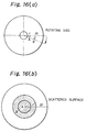
- FIG. 13 (a) shows the horizontal movement of a particle scattered through a slit at a position r away from the center of the rotating disc.
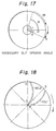
- the slits in the rotating disc are required to furnish conditions such that the particles immediately after scattering produce r 2 distribution. It has been confirmed from particle scattering experiment that the conductance is constant regardless of the slit positions of the disc (distances from the center of rotation). On this basis the shape of slits in the rotating disc will be considered. To simplify the discussion, it is presumed that each particle that has fallen to r 0 is immediately given an angular velocity ⁇ and moves in an instant to the balance point r of the mass point. Particles are continuously supplied to the hatched region in the center of FIG. 14, and then they move to the points r. As FIG.
- ideal slit shape curves will be the curves of the series shown in the formulas (8) and (9). If they are simplified and the second terms ignored, just the square curves of r will result.
- FIG. 18 is a graphic representation of the results of exemplary calculation of slit shapes.
- the base line of rotating disc must be a curve in accord with the conveyance curve of particles that move inside the disc.
- the coefficient of friction (kinetic friction coefficient) between the particle and the rotating disc is constant, and the angular velocity of rotating motion of the particle in the initial state is zero.
- the particle is subject to a centrifugal force equivalent to that in the position r O .
- the number of revolution of the rotating disc is in actual operation varied with the packed height, but here the number of revolution in the steady state of the rotating disc, m, means the number of revolution to be steadily used.
- the symbol B stands for the angle over which a particle that fell from the hopper is imparted with a rotational force by the rotating disc and is moved to attain the same number of revolution as the disc, and the angle can be found by calculation.
- the locus of movement of the particle that fell onto the center of the uniaxial spheroidal disc moves under the rotational force imparted from the disc to a number of revolution equal to that of the disc can be expressed by the above function (14) in the polar coordinate system.
- packing apparatuses were installed at different heights of 2.4 m, 1.6 m, and 0.6 m.
- the scatter region was divided into sections in such a way that the center of the packed tower was the zeroth and the inner wall of the tower was the fifth, the region in between being divided at equidistant intervals from the tower center into the first to fourth sections ( FIG. 22).
- the height is represented on the basis of the packing apparatus set at 0 m.
- the profiles, h(edge)/h(ct), of the conical packed surfaces formed during scattering at steady condition are controlled to 1 to 2.
- results given in FIG. 22 indicate that a generally flat packed surface is obtained, e.g., at the height of -2.0 mm, by performing scattering for a 2% time period on the basis of the time (100%) required for the packing from -3.0 m to -2.0 m, so that the maximum scatter distance is maintained in the first and second sections, and thereafter performing scattering for a 5.5% time period so that the maximum scatter distance is maintained in the third section.
- the packing from -3 m to -2 m is performed by: a scatter run, in such a way that the fifth section (wall surface) is the maximum scatter distance, for 5 minutes (300 seconds (100%)); a short run, in such a way that the first and second sections are the maximum scatter distance, for 6 seconds (2%); another run, in such a way that the third section is the maximum scatter distance, for 17 seconds (5,5%), and resume the run with the fifth section (wall surface) as the maximum scatter distance.
- This scatter pattern is repeated, with the result that a smoother packed surface than in FIG. 22 is obtained. Therefore, the profile of the packed surface varies within 2 ⁇ h(edge)/h(ct) ⁇ 1 .
- Example 1 Using the packing apparatus of Example 1, the catalyst particles of Example 1 were scattered and packed (scatter range: -3.6 m to -2.5 m) in an indirect desulfurization equipment of a three-layer structure (each layer 3.6 m thick) with a tower diameter of 4.1 m and height of 15 m. The bottom of the indirect desulfurization equipment was preloaded with a support catalyst and the packed surface was leveled. The surface on which the catalyst particles deposited was scanned by a laser beam to determine the packed surface condition. The number of measuring points was 100 and the measuring interval was once in 30 seconds. The measurement depended on trigonometric survey of the packed surface by semiconductor laser beam scanning and photographic observation with a CCD camera. For the laser beam a 35 mW semiconductor laser was used.
- the camera was a 1/2 in. 380,000-pixel monochromic CCD camera with a focal distance of 35 mm (minimum subject illuminance: 0.2 lux).
- a 512 x 512 pixel image processor was employed. (The laser spot coordinates were found with a recognition accuracy in an increment of 0.1 pixel.)
- the basic number of revolution of the packing apparatus (a number of revolution such that the maximum scatter distance at the height of the packed surface is the inner wall surface) was controlled as shown in Table 2, depending on the height of the packed surface.
- Each packed height in Table 2 represents the distance between the location of the packing apparatus and the packed surface, showing the relation among the maximum scatter distance, packed height, and number of revolution.
- Table 2 Packed height(m) Center Radial position Wall 0.2 m 0.6 m 1.0 m 1.4 m 1.8 m 2.0 m 0.4 70 132 188 247 309 340 0.6 61 116 172 224 274 296 0.8 52 103 151 194 234 254 1.0 49 96 140 182 219 238 1.2 46 86 131 171 206 224 1.4 44 83 122 161 193 210 1.6 42 80 114 153 185 191 1.8 40 75 109 143 176 183 2.0 39 72 105 138 170 181 2.2 37 69 100 132 164 177 2.4 35 66 98 127 157 171 2.6 34 65 94 122 151 166 2.8 33 62 92 119 147 161 3.4 32 61 89 115 143 155 The numerical values are rpm.
- FIG. 23 graphically represents an example of packing results.
- the solid lines represent the results of measurements, each with a packing monitor of a cross section of the packed surface extracted at given time intervals (the results therein being extracted at an interval of about 15 minutes from continuously sampled data). The broken lines are actually measured values confirmed by operators with a measuring tape.
- This invention has thus far been described specifically as applied to the monitoring of catalyst particle packing in a reaction vessel.
- this invention is not limited to the examples given above but is extensively applicable to the monitoring of packing of other particles in other vessels, such as packing of grains in silos.
- the particles to be handled are not specially limited, but desirable particles are non-isotropic ones, e.g., with an aspect ratio (length/width) of 2 or more, that are difficult to control in packing and particularly need to be monitored during packing.
- This invention provides a particle packing apparatus which produces a flat packed surface (uniform particle distribution height) without damaging or breaking the particles, typically catalyst particles.
- the apparatus is easy and simple to control, convenient to handle and install, and realizes high speed particle conveyance. Moreover, it makes the space presence density of particles uniform and realizes high density packing (dense loading).
- the copious data can be processed within a short time by image processing while maintaining the accuracy. The deposited particles can be distinguished from the particles being scattered.
- the smoothing of packed particle surface can be simply realized by gradually reducing the size of the cone of packed surface that is produced by the particle packing apparatus comprising a particle distributor and a packing monitor, the distributor being capable of forming a conical packed surface upon scattering of particles in a steady state (e.g., in an uncontrolled condition) and having a parameter with which to control the size of the cone.
Landscapes
- Chemical & Material Sciences (AREA)
- Physics & Mathematics (AREA)
- General Physics & Mathematics (AREA)
- Engineering & Computer Science (AREA)
- Automation & Control Theory (AREA)
- Organic Chemistry (AREA)
- Chemical Kinetics & Catalysis (AREA)
- Feeding, Discharge, Calcimining, Fusing, And Gas-Generation Devices (AREA)
- Devices And Processes Conducted In The Presence Of Fluids And Solid Particles (AREA)
- Basic Packing Technique (AREA)
- Measurement Of Levels Of Liquids Or Fluent Solid Materials (AREA)
- Length Measuring Devices By Optical Means (AREA)
Applications Claiming Priority (9)
| Application Number | Priority Date | Filing Date | Title |
|---|---|---|---|
| JP5035395 | 1995-02-16 | ||
| JP5035395 | 1995-02-16 | ||
| JP50353/95 | 1995-02-16 | ||
| JP16454995 | 1995-06-08 | ||
| JP164550/95 | 1995-06-08 | ||
| JP16455095 | 1995-06-08 | ||
| JP16455095 | 1995-06-08 | ||
| JP164549/95 | 1995-06-08 | ||
| JP16454995 | 1995-06-08 |
Publications (3)
| Publication Number | Publication Date |
|---|---|
| EP0727250A2 true EP0727250A2 (de) | 1996-08-21 |
| EP0727250A3 EP0727250A3 (de) | 1998-05-20 |
| EP0727250B1 EP0727250B1 (de) | 2003-07-23 |
Family
ID=27293932
Family Applications (1)
| Application Number | Title | Priority Date | Filing Date |
|---|---|---|---|
| EP96102369A Expired - Lifetime EP0727250B1 (de) | 1995-02-16 | 1996-02-16 | Verfahren zur Füllung von Behältern mit Teilchen |
Country Status (3)
| Country | Link |
|---|---|
| US (1) | US5731994A (de) |
| EP (1) | EP0727250B1 (de) |
| KR (1) | KR100203995B1 (de) |
Cited By (12)
| Publication number | Priority date | Publication date | Assignee | Title |
|---|---|---|---|---|
| WO2008109671A3 (en) * | 2007-03-07 | 2008-10-30 | Cat Tech Inc | Methods and apparatus for dense particle loading |
| FR2923816A1 (fr) * | 2007-11-15 | 2009-05-22 | Total France Sa | Dispositif et procede pour le chargement de particules solides dans une enceinte |
| CN102116661A (zh) * | 2010-10-19 | 2011-07-06 | 中国矿业大学(北京) | 一种基于机器视觉的料仓极限位置动态料位的检测方法 |
| WO2013057126A1 (en) | 2011-10-20 | 2013-04-25 | Akzo Nobel Chemicals International B.V. | Process for the hydrodechlorination of a liquid feed comprising dichloroacetic acid |
| WO2013057125A1 (en) | 2011-10-20 | 2013-04-25 | Akzo Nobel Chemicals International B.V. | Process for the purification of a liquid feed comprising mca and dca |
| FR2997315A1 (fr) * | 2012-10-29 | 2014-05-02 | Total Raffinage Marketing | Gestion du chargement en particules solides d'un reacteur |
| CN103939138A (zh) * | 2014-05-15 | 2014-07-23 | 中国冶金矿业鞍山冶金设计研究院有限责任公司 | 海底填砂旋转式布料器 |
| WO2015057331A1 (en) * | 2013-10-16 | 2015-04-23 | Exxonmobil Research And Engineering Company | Real-time level monitoring for fixed bed catalyst loading using multiple level sensors |
| US10131611B2 (en) | 2015-06-12 | 2018-11-20 | Akzo Nobel Chemicals International B.V. | Process for the hydrodechlorination of a feed comprising dichloroacetic acid |
| US10155714B2 (en) | 2015-03-17 | 2018-12-18 | Akzo Nobel Chemicals International B.V. | Process for the purification of monochloroacetic acid |
| CN111921460A (zh) * | 2020-06-19 | 2020-11-13 | 宁波巨化化工科技有限公司 | 一种气相醛加氢反应器 |
| CN114892662A (zh) * | 2022-04-01 | 2022-08-12 | 中交第二航务工程局有限公司 | 一种适用于地下预制结构全自动吊装方法 |
Families Citing this family (11)
| Publication number | Priority date | Publication date | Assignee | Title |
|---|---|---|---|---|
| DE19648935B4 (de) * | 1996-11-26 | 2008-05-15 | IMEDOS Intelligente Optische Systeme der Medizin- und Messtechnik GmbH | Vorrichtung und Verfahren zur Untersuchung von Gefäßen |
| US5950694A (en) * | 1998-03-04 | 1999-09-14 | Uop Llc | Apparatus for dispensing particulate material |
| US6033921A (en) | 1998-04-06 | 2000-03-07 | Advanced Micro Devices, Inc. | Method for depositing a material of controlled, variable thickness across a surface for planarization of that surface |
| US8550127B2 (en) * | 2007-08-13 | 2013-10-08 | Unidense Technology Gmbh | Catalyst loading system |
| FR2991884B1 (fr) * | 2012-06-13 | 2015-09-11 | Total Raffinage Marketing | Distribution de particules solides dans un reacteur |
| JP6028068B1 (ja) | 2015-05-12 | 2016-11-16 | 鹿島エンジニアリング株式会社 | 粒子充填装置 |
| KR102601838B1 (ko) * | 2019-04-22 | 2023-11-14 | 주식회사 엘지화학 | 촉매 입자 공급 장치 |
| DE102020210485A1 (de) | 2020-08-18 | 2022-02-24 | Vega Grieshaber Kg | Verfahren zur grafischen Darstellung von Füllstandverläufen |
| CN113624292B (zh) * | 2021-08-11 | 2022-10-04 | 重庆大学 | 给料斗内堆料体积动态测量方法及系统 |
| EP4415866A4 (de) * | 2021-10-25 | 2024-11-27 | Catmasters, Llc | Dichtes ladesystem mit wellenlader |
| CN117163350A (zh) * | 2023-09-27 | 2023-12-05 | 济南伊荣面粉有限公司 | 一种小麦粉生产用定量自动化充填机及其定量方法 |
Family Cites Families (16)
| Publication number | Priority date | Publication date | Assignee | Title |
|---|---|---|---|---|
| US3804273A (en) * | 1972-06-16 | 1974-04-16 | Atlantic Richfield Co | Catalyst distribution apparatus |
| US3972686A (en) * | 1974-01-31 | 1976-08-03 | Universal Oil Products Company | Device for loading catalyst particles into a reaction zone |
| FR2429046A1 (fr) * | 1978-06-19 | 1980-01-18 | Saint Gobain | Appareil de distribution de particules solides |
| US4433707A (en) * | 1981-09-25 | 1984-02-28 | Chevron Research Company | Method and apparatus for level loading of vessels using catalyst oriented packing |
| US4479521A (en) * | 1982-09-20 | 1984-10-30 | Gte Products Corporation | Phosphor manufacturing process |
| JPS60227155A (ja) * | 1984-04-25 | 1985-11-12 | Shimadzu Corp | 粒度分布測定装置 |
| US4972884A (en) * | 1984-12-07 | 1990-11-27 | Chevron Research & Technology Company | Method and apparatus for uniformly loading particulate material into cylindrical beds |
| US5296202A (en) * | 1984-12-07 | 1994-03-22 | Chevron Research And Technology Co. | Apparatus for uniformly loading particulate material into cylindrical beds |
| EP0257660B1 (de) * | 1986-08-29 | 1993-01-27 | FUJIREBIO KABUSHIKI KAISHA also trading as FUJIREBIO INC. | Verfahren und Gerät zur Einschätzung der Agglutination |
| CA1313040C (en) * | 1988-03-31 | 1993-01-26 | Mitsuaki Uesugi | Method and apparatus for measuring a three-dimensional curved surface shape |
| JP2750605B2 (ja) * | 1989-05-17 | 1998-05-13 | スズキ株式会社 | 粒子凝集パターン判定方法 |
| JP2874008B2 (ja) * | 1990-05-18 | 1999-03-24 | スズキ株式会社 | 粒子凝集パターン判定装置 |
| GB2246714B (en) * | 1990-08-07 | 1994-08-10 | Kanegafuchi Chemical Ind | Apparatus for powder falling gas-solid contacting operation |
| JPH05168899A (ja) * | 1991-12-25 | 1993-07-02 | Kawasaki Steel Corp | 振動造粒機の原料分配供給装置 |
| US5426501A (en) * | 1993-01-06 | 1995-06-20 | Laser Sensor Technology, Inc. | Apparatus and method for particle analysis |
| JP3001791B2 (ja) * | 1994-01-12 | 2000-01-24 | 株式会社ジャパンエナジー | 粒子充填監視方法及びその装置 |
-
1996
- 1996-02-15 US US08/602,173 patent/US5731994A/en not_active Expired - Lifetime
- 1996-02-15 KR KR1019960003655A patent/KR100203995B1/ko not_active Expired - Lifetime
- 1996-02-16 EP EP96102369A patent/EP0727250B1/de not_active Expired - Lifetime
Cited By (26)
| Publication number | Priority date | Publication date | Assignee | Title |
|---|---|---|---|---|
| US7987879B2 (en) | 2007-03-07 | 2011-08-02 | Cat Tech, Inc. | Methods and apparatus for dense particle loading |
| WO2008109671A3 (en) * | 2007-03-07 | 2008-10-30 | Cat Tech Inc | Methods and apparatus for dense particle loading |
| EA017942B1 (ru) * | 2007-11-15 | 2013-04-30 | Тоталь Рафинаж Маркетинг | Устройство и способ загрузки твердых частиц в камеру |
| FR2923816A1 (fr) * | 2007-11-15 | 2009-05-22 | Total France Sa | Dispositif et procede pour le chargement de particules solides dans une enceinte |
| WO2009098372A1 (fr) * | 2007-11-15 | 2009-08-13 | Total Raffinage Marketing | Dispositif et procede pour le chargement de particules solides dans une enceinte |
| US8948910B2 (en) | 2007-11-15 | 2015-02-03 | Total Raffinage Marketing | Device and method for loading solid particles into a chamber |
| CN102116661A (zh) * | 2010-10-19 | 2011-07-06 | 中国矿业大学(北京) | 一种基于机器视觉的料仓极限位置动态料位的检测方法 |
| CN102116661B (zh) * | 2010-10-19 | 2012-07-25 | 中国矿业大学(北京) | 一种基于机器视觉的料仓极限位置动态料位的检测方法 |
| WO2013057126A1 (en) | 2011-10-20 | 2013-04-25 | Akzo Nobel Chemicals International B.V. | Process for the hydrodechlorination of a liquid feed comprising dichloroacetic acid |
| US9505694B2 (en) | 2011-10-20 | 2016-11-29 | Akzo Nobel Chemicals International B.V. | Process for the purification of a liquid feed comprising MCA and DCA |
| WO2013057125A1 (en) | 2011-10-20 | 2013-04-25 | Akzo Nobel Chemicals International B.V. | Process for the purification of a liquid feed comprising mca and dca |
| US9505693B2 (en) | 2011-10-20 | 2016-11-29 | Akzo Nobel Chemicals International B.V. | Process for the hydrodechlorination of a liquid feed comprising dichloroacetic acid |
| WO2014068232A1 (fr) | 2012-10-29 | 2014-05-08 | Total Raffinage Chimie | Gestion du chargement en particules solides d'un reacteur |
| US9889419B2 (en) | 2012-10-29 | 2018-02-13 | Total Raffinage Chimie | Management of the charging of a reactor with solid particles |
| FR2997315A1 (fr) * | 2012-10-29 | 2014-05-02 | Total Raffinage Marketing | Gestion du chargement en particules solides d'un reacteur |
| CN104768637B (zh) * | 2012-10-29 | 2017-08-08 | 道达尔炼油化学公司 | 用固体颗粒对反应器装料的管理 |
| WO2015057331A1 (en) * | 2013-10-16 | 2015-04-23 | Exxonmobil Research And Engineering Company | Real-time level monitoring for fixed bed catalyst loading using multiple level sensors |
| CN103939138B (zh) * | 2014-05-15 | 2015-12-23 | 中国冶金矿业鞍山冶金设计研究院有限责任公司 | 海底填砂旋转式布料器 |
| CN103939138A (zh) * | 2014-05-15 | 2014-07-23 | 中国冶金矿业鞍山冶金设计研究院有限责任公司 | 海底填砂旋转式布料器 |
| US10155714B2 (en) | 2015-03-17 | 2018-12-18 | Akzo Nobel Chemicals International B.V. | Process for the purification of monochloroacetic acid |
| US10131611B2 (en) | 2015-06-12 | 2018-11-20 | Akzo Nobel Chemicals International B.V. | Process for the hydrodechlorination of a feed comprising dichloroacetic acid |
| CN111921460A (zh) * | 2020-06-19 | 2020-11-13 | 宁波巨化化工科技有限公司 | 一种气相醛加氢反应器 |
| CN111921460B (zh) * | 2020-06-19 | 2021-03-16 | 宁波巨化化工科技有限公司 | 一种气相醛加氢反应器 |
| WO2021254193A1 (zh) * | 2020-06-19 | 2021-12-23 | 宁波巨化化工科技有限公司 | 一种气相醛加氢反应器 |
| CN114892662A (zh) * | 2022-04-01 | 2022-08-12 | 中交第二航务工程局有限公司 | 一种适用于地下预制结构全自动吊装方法 |
| CN114892662B (zh) * | 2022-04-01 | 2023-12-29 | 中交第二航务工程局有限公司 | 一种适用于地下预制结构全自动吊装方法 |
Also Published As
| Publication number | Publication date |
|---|---|
| KR100203995B1 (ko) | 1999-06-15 |
| EP0727250A3 (de) | 1998-05-20 |
| EP0727250B1 (de) | 2003-07-23 |
| US5731994A (en) | 1998-03-24 |
Similar Documents
| Publication | Publication Date | Title |
|---|---|---|
| EP0727250B1 (de) | Verfahren zur Füllung von Behältern mit Teilchen | |
| JP5243549B2 (ja) | 固体粒子をチャンバー内に堆積させる堆積装置及び堆積方法 | |
| JP2870346B2 (ja) | 竪型炉の装入物プロフィール測定方法および測定装置 | |
| US4433707A (en) | Method and apparatus for level loading of vessels using catalyst oriented packing | |
| CN1484017A (zh) | 用于带条卷烟纸制造的光学检查系统 | |
| US4243351A (en) | Method of and apparatus for charging a furnace | |
| US4529305A (en) | Examining a gemstone | |
| JPH08294785A (ja) | 3次元物体の製造方法および装置 | |
| EP0398455B1 (de) | Verfahren und Einrichtung zur Herstellung rotationssymmetrischer Körper | |
| JP2939178B2 (ja) | 粒子充填装置における粒子充填面の平滑化方法 | |
| JPH07242337A (ja) | 粒子充填監視方法及びその装置 | |
| EP0359230A1 (de) | Vorrichtung zum Agglomerieren von Material | |
| JP6905648B1 (ja) | 炉壁の損耗量測定装置及び炉壁の損耗量測定方法 | |
| JP2939179B2 (ja) | 粒子充填監視方法 | |
| JP3018943B2 (ja) | 高炉炉壁プロフィール測定方法及びその装置 | |
| JP3133672B2 (ja) | 粒子散布装置 | |
| JPH06212223A (ja) | 炉中原料混合物の表面輪郭測定装置 | |
| US5753585A (en) | Method of packing catalyst | |
| JPH085682B2 (ja) | 鋳型への粉体耐火性材料の充填を制御する方法及び装置 | |
| KR20160146489A (ko) | 알루미늄 시트 금속에 선택된 지형을 부여하기 위한 장치와 방법, 및 이를 위한 적용례 | |
| JP3865666B2 (ja) | ペ−スト塗布装置およびペ−スト塗布方法 | |
| JP3372342B2 (ja) | 糖衣コーティング方法および装置 | |
| JP3345723B2 (ja) | 流動層又は転動流動層造粒装置 | |
| GB2236428A (en) | Process for coating phosphor slurry on a cathode ray tube | |
| JP3185451B2 (ja) | 粒度分布測定用粉体供給装置 |
Legal Events
| Date | Code | Title | Description |
|---|---|---|---|
| PUAI | Public reference made under article 153(3) epc to a published international application that has entered the european phase |
Free format text: ORIGINAL CODE: 0009012 |
|
| AK | Designated contracting states |
Kind code of ref document: A2 Designated state(s): BE FR GB |
|
| PUAL | Search report despatched |
Free format text: ORIGINAL CODE: 0009013 |
|
| AK | Designated contracting states |
Kind code of ref document: A3 Designated state(s): BE FR GB |
|
| 17P | Request for examination filed |
Effective date: 19980731 |
|
| 17Q | First examination report despatched |
Effective date: 20020627 |
|
| GRAH | Despatch of communication of intention to grant a patent |
Free format text: ORIGINAL CODE: EPIDOS IGRA |
|
| RTI1 | Title (correction) |
Free format text: METHOD OF PACKING PARTICLES INTO VESSELS |
|
| RTI1 | Title (correction) |
Free format text: METHOD OF PACKING PARTICLES INTO VESSELS |
|
| RTI1 | Title (correction) |
Free format text: METHOD OF PACKING PARTICLES INTO VESSELS |
|
| GRAH | Despatch of communication of intention to grant a patent |
Free format text: ORIGINAL CODE: EPIDOS IGRA |
|
| GRAA | (expected) grant |
Free format text: ORIGINAL CODE: 0009210 |
|
| AK | Designated contracting states |
Designated state(s): BE FR GB |
|
| REG | Reference to a national code |
Ref country code: GB Ref legal event code: FG4D |
|
| ET | Fr: translation filed | ||
| PLBE | No opposition filed within time limit |
Free format text: ORIGINAL CODE: 0009261 |
|
| STAA | Information on the status of an ep patent application or granted ep patent |
Free format text: STATUS: NO OPPOSITION FILED WITHIN TIME LIMIT |
|
| 26N | No opposition filed |
Effective date: 20040426 |
|
| REG | Reference to a national code |
Ref country code: GB Ref legal event code: 732E |
|
| REG | Reference to a national code |
Ref country code: FR Ref legal event code: TP |
|
| REG | Reference to a national code |
Ref country code: FR Ref legal event code: PLFP Year of fee payment: 20 |
|
| PGFP | Annual fee paid to national office [announced via postgrant information from national office to epo] |
Ref country code: GB Payment date: 20150211 Year of fee payment: 20 Ref country code: FR Payment date: 20150210 Year of fee payment: 20 |
|
| PGFP | Annual fee paid to national office [announced via postgrant information from national office to epo] |
Ref country code: BE Payment date: 20150211 Year of fee payment: 20 |
|
| REG | Reference to a national code |
Ref country code: GB Ref legal event code: PE20 Expiry date: 20160215 |
|
| PG25 | Lapsed in a contracting state [announced via postgrant information from national office to epo] |
Ref country code: GB Free format text: LAPSE BECAUSE OF EXPIRATION OF PROTECTION Effective date: 20160215 |