EP0727275A1 - Procédé de soudage des extrémités de tubes minces d'échangeurs de chaleur sans laisser de fentes résiduelles - Google Patents
Procédé de soudage des extrémités de tubes minces d'échangeurs de chaleur sans laisser de fentes résiduelles Download PDFInfo
- Publication number
- EP0727275A1 EP0727275A1 EP96100883A EP96100883A EP0727275A1 EP 0727275 A1 EP0727275 A1 EP 0727275A1 EP 96100883 A EP96100883 A EP 96100883A EP 96100883 A EP96100883 A EP 96100883A EP 0727275 A1 EP0727275 A1 EP 0727275A1
- Authority
- EP
- European Patent Office
- Prior art keywords
- welding
- heat exchanger
- tubes
- wall
- tube
- Prior art date
- Legal status (The legal status is an assumption and is not a legal conclusion. Google has not performed a legal analysis and makes no representation as to the accuracy of the status listed.)
- Withdrawn
Links
- 238000000034 method Methods 0.000 title claims abstract description 30
- 238000003466 welding Methods 0.000 title claims abstract description 30
- 239000011261 inert gas Substances 0.000 claims abstract description 6
- WFKWXMTUELFFGS-UHFFFAOYSA-N tungsten Chemical compound [W] WFKWXMTUELFFGS-UHFFFAOYSA-N 0.000 claims abstract description 4
- 229910052721 tungsten Inorganic materials 0.000 claims abstract description 4
- 239000010937 tungsten Substances 0.000 claims abstract description 4
- 239000000463 material Substances 0.000 claims description 6
- 230000001681 protective effect Effects 0.000 claims description 2
- 239000000945 filler Substances 0.000 abstract description 2
- 239000007789 gas Substances 0.000 abstract 1
- 229910052751 metal Inorganic materials 0.000 abstract 1
- 239000002184 metal Substances 0.000 abstract 1
- 230000001012 protector Effects 0.000 abstract 1
- 239000000919 ceramic Substances 0.000 description 8
- 238000010276 construction Methods 0.000 description 1
- 238000005260 corrosion Methods 0.000 description 1
- 230000007797 corrosion Effects 0.000 description 1
- 238000005553 drilling Methods 0.000 description 1
- 230000000694 effects Effects 0.000 description 1
- 239000000155 melt Substances 0.000 description 1
- XLYOFNOQVPJJNP-UHFFFAOYSA-N water Substances O XLYOFNOQVPJJNP-UHFFFAOYSA-N 0.000 description 1
Images
Classifications
-
- B—PERFORMING OPERATIONS; TRANSPORTING
- B23—MACHINE TOOLS; METAL-WORKING NOT OTHERWISE PROVIDED FOR
- B23K—SOLDERING OR UNSOLDERING; WELDING; CLADDING OR PLATING BY SOLDERING OR WELDING; CUTTING BY APPLYING HEAT LOCALLY, e.g. FLAME CUTTING; WORKING BY LASER BEAM
- B23K9/00—Arc welding or cutting
- B23K9/02—Seam welding; Backing means; Inserts
- B23K9/028—Seam welding; Backing means; Inserts for curved planar seams
- B23K9/0288—Seam welding; Backing means; Inserts for curved planar seams for welding of tubes to tube plates
-
- F—MECHANICAL ENGINEERING; LIGHTING; HEATING; WEAPONS; BLASTING
- F28—HEAT EXCHANGE IN GENERAL
- F28F—DETAILS OF HEAT-EXCHANGE AND HEAT-TRANSFER APPARATUS, OF GENERAL APPLICATION
- F28F9/00—Casings; Header boxes; Auxiliary supports for elements; Auxiliary members within casings
- F28F9/02—Header boxes; End plates
- F28F9/04—Arrangements for sealing elements into header boxes or end plates
- F28F9/16—Arrangements for sealing elements into header boxes or end plates by permanent joints, e.g. by rolling
- F28F9/18—Arrangements for sealing elements into header boxes or end plates by permanent joints, e.g. by rolling by welding
-
- B—PERFORMING OPERATIONS; TRANSPORTING
- B23—MACHINE TOOLS; METAL-WORKING NOT OTHERWISE PROVIDED FOR
- B23K—SOLDERING OR UNSOLDERING; WELDING; CLADDING OR PLATING BY SOLDERING OR WELDING; CUTTING BY APPLYING HEAT LOCALLY, e.g. FLAME CUTTING; WORKING BY LASER BEAM
- B23K2101/00—Articles made by soldering, welding or cutting
- B23K2101/04—Tubular or hollow articles
- B23K2101/14—Heat exchangers
Definitions
- the invention relates to a method for the gap-free welding of the ends of thin-walled heat exchanger tubes with the wall separating the media involved in the heat exchange, the bores corresponding to the inner diameter of the tubes and these bores surrounding attachment surfaces for end faces formed on the tube ends, before by means of an inside of the The end face of the pipes are welded to the attachment surfaces of the circumferential welding head, the welding being carried out without the addition of an additional material and using a weld pool lock on the outside of the pipe.
- Such a method is e.g. known from DE 38 22 807 C1.
- the pipe ends are attached to the back of a pipe plate that is provided with holes that correspond to the inside diameter of the pipes. Collars machined from the back material of the tube plates are arranged concentrically around these bores, on the end faces of which the corresponding end faces of the centered tubes are placed.
- the parts are then connected by means of a welding head which can be inserted into the inside of the bore and runs there. Since the pipe ends are connected to the back of the pipe plate, there are no remaining gaps, which are often the cause of uncontrollable corrosion.
- the number of pipes to be fastened to a pipe plate according to the known method is limited by the spacing between the individual pipes which has to be observed for welding reasons.
- the after Processes according to DE 38 22 807 C1 machined tube plates therefore require a relatively large tube plate in order to accommodate a sufficient number of tube ends, which in turn leads to a correspondingly large overall diameter of the heat exchanger.
- the invention has for its object to develop the known method for the gap-free welding of the ends of thin-walled heat exchanger tubes so that with unchanged good access to the welds, either the number of heat exchanger tubes can be increased while the outside diameter of the heat exchanger remains unchanged, or the number of heat exchanger tubes remains the same Total diameter of the heat exchanger can be reduced.
- a section of a cylindrical collector is used as the wall separating the media involved, the outwardly curved outer surface of the section being provided with the attachment surfaces.
- the pitch i.e. reduce the distance between adjacent pipe ends, compared to the known method.
- This can either be used to reduce the diameter of the heat exchanger in the area of the collector for the same number of heat exchanger tubes, or alternatively to increase the number of heat exchanger tubes with the same diameter of the heat exchanger, and thus to increase the heat transfer capacity.
- the collector is composed of two half-shells.
- One half-shell is with the one Provide bores leading heat exchanger tubes, while the other half-shell is assembled with the first half-shell to form the then closed collector only after all welding work has been completed.
- the inside diameter of the collector should be at least 400 mm according to a development of the method.
- the tube ends are welded to the wall separating the media involved using an inert gas protective welding method, in particular a tungsten inert gas welding method (TIG).
- an inert gas protective welding method in particular a tungsten inert gas welding method (TIG).
- the attachment surfaces and end faces are machined.
- the welding process is therefore carried out with a smooth, flat weld joint running at right angles to the longitudinal axis of the tube, which is simple to produce and can be cleaned very easily with simple means.
- the centering of the pipe with respect to the bore, which is required in this procedure, can take place via an external ceramic ring.
- Such a ceramic ring also represents a reliable weld pool safety device which prevents the melt from escaping on the outer surface of the joint.
- An essential aspect of the invention is to accommodate an increased number of heat exchanger tubes on the wall separating the media involved in the heat exchange, by reducing the distance between the individual tube ends compared to the known methods.
- the ratio of the pipe center point distance to the pipe diameter is at most 1.5.
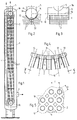
- the heat exchanger shown schematically in Fig. 1 consists of a welded outer jacket 1, a bundle of heat exchanger tubes 2 arranged coaxially therein and two collectors 3a, 3b closing the heat exchanger up and down, into which the thin-walled tubes 2 open.
- One medium e.g. Water passes through a channel 4 into the collector 3b arranged at the bottom in FIG. 1, flows from there through the pipes 2 to the upper collector 3a, and leaves it via the outlet 5.
- the other medium, e.g. Hot air enters the interior of the essentially cylindrical outer jacket 1 via the inlet connector 7, flows through it in countercurrent to the other medium into the tube bundle, and leaves the interior via the outlet connector 6.
- baffle plates 8 bring this through the feed connector 6 into the Medium coming heat exchanger for a frequent change of direction, so that the heat exchange takes place essentially in the manner of a cross-counterflow.
- FIGS. 2 and 3 show details of the upper header 3a, including the pipes 2 connected to it. From the tubes 2 is out For the sake of clarity, only the center line is drawn.
- the collector 3a like the correspondingly constructed collector 3b, has a cylindrical base body made of two half-shells 8, 9 and two circular plates 10 closing the end faces.
- the upper half-shell 8 is connected to the inlet connection 5, while the lower half-shell 9 welded to the upper half-shell 8 is welded to all the tubes 2 of the tube bundle.
- the collector 3a arranged within the heat exchanger thus forms a chamber, in the interior of which there is one medium involved in the heat exchange and outside which the other medium involved in the heat exchange is located. A section of this chamber is the lower half-shell 9, which in this way forms a wall which separates the media involved in the heat exchange.
- the outwardly curved outer surface 11 of the half-shell 9 forming the lower section of the collector 3a makes it possible to accommodate more attachment points for pipes 2 than is the case with a flat-shaped tube sheet. It is not necessary that the cylindrical collector 3a is designed as a circular cylinder. A cylinder with an elliptical cross-sectional area can be used with the same advantage.
- Fig. 4 it is shown that the wall 12 of the collector 3a in the region of the lower half-shell 9 is provided with a plurality of identical bores 13.
- Each bore 13 is concentrically surrounded on the outside of the wall 12 formed by the half-shell 9 by a collar 15 which has been worked out of the material on the outer surface 11 of the wall 12 and forms a shoulder surface 17 running at right angles to the axis 16 of the bore.
- this attachment surface 17 With this attachment surface 17, the end surface 18 formed at the end of each thin-walled tube 2 is welded without any residual gap without the use of an additional material.
- a ceramic ring Before welding, a ceramic ring can be pushed onto the end of the tube 2, which surrounds the tube 2 and the collar 15 as tightly as possible. Such a ceramic ring is pushed over the weld joint formed by the shoulder surface 17 and the end surface 18 as soon as the end of the tube 2 has been attached to the collar 15. The ceramic ring then effects on the one hand a centering of the tube 2 with respect to the collar 15 Wall 12. In addition, such a ceramic ring serves as a bath safety device during the welding process. This welding process takes place without filler material by means of a welding head rotating in the interior of the bore 13, for example according to the tungsten inert gas welding process (TIG).
- TIG tungsten inert gas welding process
- the welding head is guided through the interior of the half-shell 9 into the bore 13, then the welding electrode is placed at the junction of the attachment surface 17 and the end surface 18, and the welding head is then rotated about its own axis.
- the use of a ceramic ring prevents the weld pool from escaping into the spaces between the individual tubes. After the weld seam has cooled, the ceramic ring is destroyed.
- FIGS. 4 and 5 show that the working out of the collars 15 takes place by incorporating a groove 19 running coaxially around the bore 13 into the outside of the wall 12. From the top view in FIG. 5 it can also be seen that the annular grooves 19 of the individual bores 13 partially run into one another or overlap in those regions in which the tubes 2 come closest. In this way, the smallest possible distance between the individual tubes 2 is possible.
- the ratio of the pipe center point distance (the pitch) T shown in FIG. 5 to the pipe diameter D is at most 1.5.
- the collectors 3a, 3b shown in the drawing initially have separate half-shells 8,9. Only after all the tubes 2 have been fastened in the manner described to the outwardly facing lateral surface 11 of the half-shell 9 is the other half-shell 8 attached, and closed by means of the weld seam 14 and by attaching the circular plates 10 to the collectors.
- the inside diameter of the collector 3a, 3b is at least 400 mm.
Landscapes
- Engineering & Computer Science (AREA)
- Physics & Mathematics (AREA)
- Mechanical Engineering (AREA)
- Plasma & Fusion (AREA)
- Thermal Sciences (AREA)
- General Engineering & Computer Science (AREA)
- Details Of Heat-Exchange And Heat-Transfer (AREA)
- Heat-Exchange Devices With Radiators And Conduit Assemblies (AREA)
Applications Claiming Priority (2)
| Application Number | Priority Date | Filing Date | Title |
|---|---|---|---|
| DE19505532 | 1995-02-18 | ||
| DE19505532A DE19505532A1 (de) | 1995-02-18 | 1995-02-18 | Verfahren zum restspaltfreien Verschweißen der Enden dünnwandiger Wärmetauscherrohre |
Publications (1)
| Publication Number | Publication Date |
|---|---|
| EP0727275A1 true EP0727275A1 (fr) | 1996-08-21 |
Family
ID=7754339
Family Applications (1)
| Application Number | Title | Priority Date | Filing Date |
|---|---|---|---|
| EP96100883A Withdrawn EP0727275A1 (fr) | 1995-02-18 | 1996-01-23 | Procédé de soudage des extrémités de tubes minces d'échangeurs de chaleur sans laisser de fentes résiduelles |
Country Status (2)
| Country | Link |
|---|---|
| EP (1) | EP0727275A1 (fr) |
| DE (1) | DE19505532A1 (fr) |
Cited By (4)
| Publication number | Priority date | Publication date | Assignee | Title |
|---|---|---|---|---|
| CN101862917A (zh) * | 2010-06-11 | 2010-10-20 | 鲁西工业装备有限公司 | 双管板换热器设备的焊制工艺 |
| CN101628354B (zh) * | 2009-08-18 | 2011-08-10 | 四川蓝星机械有限公司 | 换热器中换热管与管板的内孔焊接方法 |
| CN103817415A (zh) * | 2014-02-26 | 2014-05-28 | 睿能(沈阳)热泵技术有限公司 | 一种钛超薄壁管的焊接方法 |
| CN105710549A (zh) * | 2016-02-06 | 2016-06-29 | 保定多田冷却设备有限公司 | 一种变压器用风冷却器不锈钢冷却管和管板焊接工艺 |
Citations (3)
| Publication number | Priority date | Publication date | Assignee | Title |
|---|---|---|---|---|
| DE2219960A1 (de) * | 1972-04-24 | 1973-11-08 | Kraftwerk Union Ag | Speisewasservorwaermer |
| JPS5747194A (en) * | 1980-09-01 | 1982-03-17 | Babcock Hitachi Kk | Heat exchanger |
| DE3822807C1 (en) * | 1988-07-06 | 1990-01-11 | Balcke-Duerr Ag, 4030 Ratingen, De | Method of welding thin-walled heat-exchanger tubes to the rear of a tube plate |
-
1995
- 1995-02-18 DE DE19505532A patent/DE19505532A1/de not_active Withdrawn
-
1996
- 1996-01-23 EP EP96100883A patent/EP0727275A1/fr not_active Withdrawn
Patent Citations (3)
| Publication number | Priority date | Publication date | Assignee | Title |
|---|---|---|---|---|
| DE2219960A1 (de) * | 1972-04-24 | 1973-11-08 | Kraftwerk Union Ag | Speisewasservorwaermer |
| JPS5747194A (en) * | 1980-09-01 | 1982-03-17 | Babcock Hitachi Kk | Heat exchanger |
| DE3822807C1 (en) * | 1988-07-06 | 1990-01-11 | Balcke-Duerr Ag, 4030 Ratingen, De | Method of welding thin-walled heat-exchanger tubes to the rear of a tube plate |
Non-Patent Citations (1)
| Title |
|---|
| PATENT ABSTRACTS OF JAPAN vol. 006, no. 120 (M - 140) 3 July 1982 (1982-07-03) * |
Cited By (7)
| Publication number | Priority date | Publication date | Assignee | Title |
|---|---|---|---|---|
| CN101628354B (zh) * | 2009-08-18 | 2011-08-10 | 四川蓝星机械有限公司 | 换热器中换热管与管板的内孔焊接方法 |
| CN101862917A (zh) * | 2010-06-11 | 2010-10-20 | 鲁西工业装备有限公司 | 双管板换热器设备的焊制工艺 |
| CN101862917B (zh) * | 2010-06-11 | 2012-07-18 | 鲁西工业装备有限公司 | 双管板换热器设备的焊制工艺 |
| CN103817415A (zh) * | 2014-02-26 | 2014-05-28 | 睿能(沈阳)热泵技术有限公司 | 一种钛超薄壁管的焊接方法 |
| CN103817415B (zh) * | 2014-02-26 | 2015-11-25 | 睿能(沈阳)热泵技术有限公司 | 一种钛超薄壁管的焊接方法 |
| CN105710549A (zh) * | 2016-02-06 | 2016-06-29 | 保定多田冷却设备有限公司 | 一种变压器用风冷却器不锈钢冷却管和管板焊接工艺 |
| CN105710549B (zh) * | 2016-02-06 | 2018-05-01 | 保定多田冷却设备有限公司 | 一种变压器用风冷却器不锈钢冷却管和管板焊接工艺 |
Also Published As
| Publication number | Publication date |
|---|---|
| DE19505532A1 (de) | 1996-08-22 |
Similar Documents
| Publication | Publication Date | Title |
|---|---|---|
| DE2408120C3 (de) | Vorrichtung zum Verbinden zweier rohrförmiger Elemente durch Reibschweißen | |
| EP0108193B2 (fr) | Presse à courber des tubes | |
| EP0233339B1 (fr) | Pièce avec des nervures et son procédé de fabrication | |
| EP0022063B1 (fr) | Dispositif d'évacuation des gaz d'échappement pour moteurs à combustion interne et procédé pour sa fabrication | |
| DE2236758A1 (de) | Schweissverfahren und vorrichtung zu seiner durchfuehrung | |
| DE3015905C2 (fr) | ||
| EP1518043A2 (fr) | Echangeur thermique pour gaz d'echappement et procede de fabrication associe | |
| DE68920203T2 (de) | Vorrichtung zum Festschweissen eines Endstopfens mit im Durchmesser reduzierter Schulter mit dem Rohr eines abbrennbaren Neutronenabsorberstabs. | |
| DE69404273T2 (de) | Wärmetauscher mit verbessertem Stabschirm | |
| EP0116687A1 (fr) | Dispositif pour introduire du gaz dans deux tubes à souder l'un à l'autre, en particulier tubes de petit diamètre | |
| EP0727275A1 (fr) | Procédé de soudage des extrémités de tubes minces d'échangeurs de chaleur sans laisser de fentes résiduelles | |
| DE19715016A1 (de) | Zweiteiliges Gehäuse und Verfahren zu seiner Fertigung | |
| EP0104325B1 (fr) | Procédé pour souder des pièces usinées cylindriques et plaquées intérieurement | |
| DE3306984A1 (de) | Supraleitender generator mit waermestrahlungsabschirmung | |
| DE2717558C2 (fr) | ||
| EP0223912B1 (fr) | Dispositif de refroidissement de gaz chauds chargés de poussière | |
| EP0818659A2 (fr) | Distributeur pour des médias différents dans des circuits d'alimentation, spécialement dans des systèmes de chauffage et méthode de production | |
| EP0411459B1 (fr) | Dispositif pour centrer et tendre des pièces à usiner de tuyaux | |
| DE2320125A1 (de) | Verfahren zur herstellung einer rohreinheit | |
| DE102012216092A1 (de) | Verfahren zur Herstellung von Rohrbündelwärmeübertragern sowie Vorrichtung zur Durchführung des Verfahrens | |
| DE2918537C2 (de) | Vorrichtung zum Entgraten von widerstandsstumpfgeschweißten Rohren | |
| DE3605494C2 (fr) | ||
| DE2913444A1 (de) | Gegenstromwaermeaustauscher mit zwei festen rohrplatten | |
| DE69318284T2 (de) | Verfahren zur Herstellung von Heizkörperelementen für Zentralheizungsanlagen | |
| EP0108423A1 (fr) | Procédé et dispositif pour enrober d'une manière continue des tuyaux en matière synthétique dans une enveloppe de protection |
Legal Events
| Date | Code | Title | Description |
|---|---|---|---|
| PUAI | Public reference made under article 153(3) epc to a published international application that has entered the european phase |
Free format text: ORIGINAL CODE: 0009012 |
|
| AK | Designated contracting states |
Kind code of ref document: A1 Designated state(s): AT BE CH DE DK ES FR GB GR IE IT LI NL PT SE |
|
| 17P | Request for examination filed |
Effective date: 19960730 |
|
| 17Q | First examination report despatched |
Effective date: 19961106 |
|
| STAA | Information on the status of an ep patent application or granted ep patent |
Free format text: STATUS: THE APPLICATION HAS BEEN WITHDRAWN |
|
| 18W | Application withdrawn |
Withdrawal date: 19970313 |